Challenger RoGator RG900C RG1100C RG1300C Chassis Operator Manual PDF
Original price was: $89.95.$25.95Current price is: $25.95.
Challenger EU Applicators RG900C RG1100C RG1300C RoGator Chassis Operator’s Manual 607992D1B – PDF DOWNLOAD
Description
Challenger EU Applicators RG900C RG1100C RG1300C RoGator Chassis Operator’s Manual 607992D1B – PDF DOWNLOAD
DESCRIPTION:
Challenger EU Applicators RG900C RG1100C RG1300C RoGator Chassis Operator’s Manual 607992D1B – PDF DOWNLOAD
Prepare for operation:
Read and understand all operation instructions and precautions in this manual before you operate the machine or do the servicing. Make sure that you know and understand the positions and operations of all controls. Make sure that all controls are in neutral and that the parking brake is applied before you start the machine. Make sure that all persons are away from your area of work before you start and operate the machine.
- Examine and learn the controls in an area that is clear of persons and obstacles before you start work. Know the machine dimensions and make sure that you have sufficient space available to operate the machine.
- Do not operate the machine at high speeds in crowded areas. It is important to know and use the correct procedures when you do work around and operate the machine. Do not let children or unqualified persons operate the machine.
- Keep others, especially children, away from your area of work. Do not let others ride on the machine. Make sure that the machine is in good condition for operation. Refer to the operator manual. Make sure that the machine has the correct equipment required by local regulations.
TABLE OF CONTENTS:
Challenger EU Applicators RG900C RG1100C RG1300C RoGator Chassis Operator’s Manual 607992D1B – PDF DOWNLOAD
1 Safety 13
1 1 Important safety information 15
1 1 1 Prepare for operation 1 5
1 1 2 A word to the operator 16
1 1 3 Safety symbol 17
1 1 4 Safety messages 17
1 1 5 Information messages 17
1 1 6 Follow safety instructions 1 8
1 1 7 Prepare for emergencies 1 8
1 1 8 Fire prevention 1 9
1 1 9 Prevent static discharge when fueling 1 9
1 1 10 Exit the cab in an emergency 1 9
1 2 Operate the machine 21
1 2 1 Prevent machine runaway 2 2
1 2 2 Use correct lamps and markers 2 2
1 2 3 Operation on slopes 2 2
1 2 4 Travel on public roads 2 3
1 2 5 Stop and park 2 3
1 2 6 System boom operation 2 3
1 2 7 Exhaust fumes 2 4
1 2 8 Noise prevention 2 4
1 2 9 Handle fuel correctly 2 4
1 2 10 Towing 2 5
1 2 1 1 Modifications 2 5
1 3 Maintenance and service 26
1 3 1 Practice correct maintenance 26
1 3 2 Chemical safety 27
1 3 3 Work in a clean area 2 9
1 3 4 Understand correct service 30
1 3 5 Use correct tools 30
1 3 6 Support machine correctly 3 1
1 3 7 High pressure fluids 3 1
1 3 8 Service cooling system correctly 3 2
1 3 9 Remove paint before welding or heating 3 2
1 3 10 T ires and wheels 3 3
1 3 1 1 Mobile radio installations 3 3
1 3 1 2 Fire prevention 3 3
1 4 Cab safety signs 35
1 4 1 Read manual 36
1 4 2 Break glass – exit 36
1 4 3 Sound horn 36
1 4 4 Electrical hazard 36
1 4 5 Run-over hazard 37
1 4 6 Cab filter number 2 37
1 4 7 Cab filter number 3 37
1 4 8 Cab filter number 1 37
1 4 9 Roll over – wear seat belt 3 8
1 4 10 Run over – no riders 3 8
1 5 Electrical signs 39
1 5 1 Radar hazard 40
1 5 2 Electrocution hazard 40
Applicator Chassis
607992018
Table of contents
1 5 3 Fuse/relay and battery sign 40
1 5 4 Battery box fuse/relay sign – 6 0 2 6 9 2D1 40
1 5 5 Cab fuse/relay sign – ACW71 4 5 6 6 0 4 1
1 6 Chassis signs 42
1 6 1 Fall off hazard 4 3
1 6 2 Air dump 4 3
1 6 3 Roll over 4 3
1 6 4 Pinch hazard 4 3
1 6 5 Tie down 4 4
1 6 6 Lift point 4 4
1 6 7 Drain the air tank 4 4
1 6 8 Hand wash 4 4
1 6 9 Axle spacing left-hand 4 5
1 6 10 Axle spacing right-hand 4 5
1 7 Hydraulic signs 46
1 7 1 Explosion injury hazard 4 7
1 7 2 High pressure hazard 4 7
1 8 Engine signs 48
1 8 1 Separator filter 4 9
1 8 2 Fuel filter 4 9
1 8 3 Fuel water separator head 4 9
1 8 4 High pressure hazard 5 0
1 8 5 Entanglement 5 0
1 8 6 Entanglement 5 0
1 8 7 Run over hazard 5 1
1 8 8 Ether 5 1
1 8 9 Diesel exhaust fluid filter 5 1
1 8 10 Fuel filter 5 1
1 8 1 1 Burn hazard 5 2
2 Introduction 53
2 1 Introduction 55
2 1 1 Intended use 5 5
2 1 2 Proper disposal of waste 5 5
2 1 3 Pre-delivery checklist 5 5
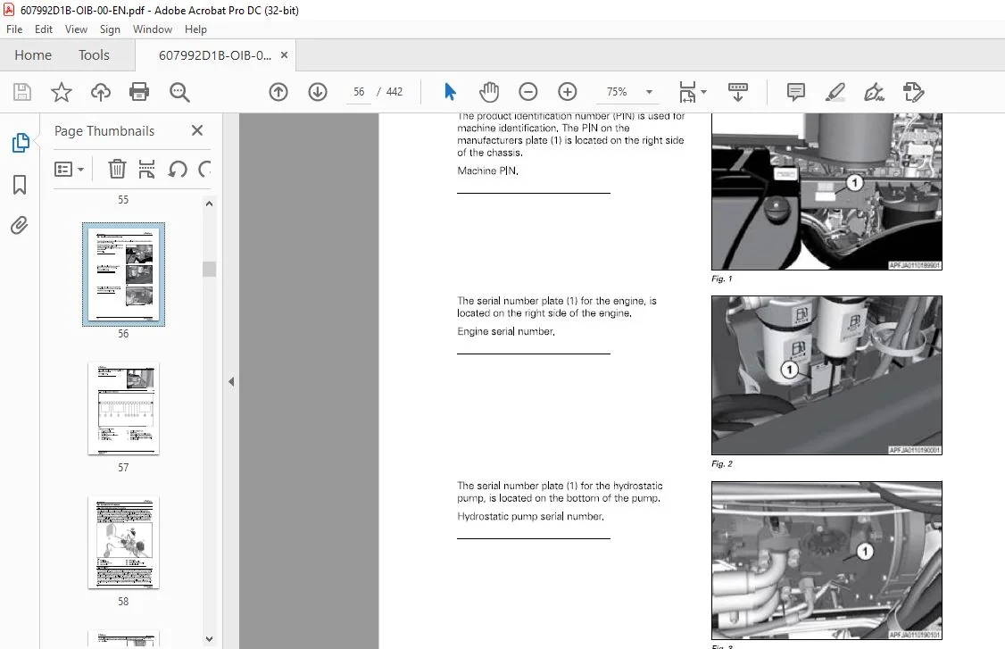
2 2 Serial number identification 56
2 2 1 Serial number definition 5 7
2 3 Hydrostatic drive system 58
2 3 1 Hydrostatic drive system introduction 5 8
2 3 2 Drive lever 5 8
2 3 3 Hydraulic drive pump 5 9
2 3 4 Charge pump 5 9
2 3 5 Oil cooler 6 0
2 3 6 Hydraulic system oil filters 6 0
2 4 Component locations 62
2 5 Fuses and relays 64
2 5 1 Fuse/relay panel 6 4
2 5 2 Main fuses 71
2 5 3 Chassis harness fuses 71
2 5 4 Power distribution module 71
2 6 Selective catalytic reduction (SCR) System 74
2 6 1 Diesel exhaust fluid (DEF) tank 74
2 6 2 Diesel exhaust fluid (DEF) storage 74
2 7 Emissions warranty 75
2 7 1 United States and Canada emission control warranty statement 75
2 7 2 California emission control warranty statement 78
Applicator Chassis
607992018
Table of contents
3 Operation 83
3 1 Instruments and controls 87
3 1 1 Dash panel 8 7
3 1 2 Operating status displays 8 8
3 1 3 Multiple display screens 8 8
3 1 4 How to clear dash panel fault codes 8 9
3 1 5 Console keypad 9 1
3 1 6 Ignition switch 9 2
3 1 7 Multifunction lever 9 3
3 1 8 Set the windshield wiper delay 9 3
3 1 9 Tilt – telescoping lever 9 4
3 1 10 Brake pedal 9 4
3 1 1 1 Drive lever controls 9 5
3 1 1 2 Armrest controls 9 5
3 1 1 3 Armrest adjustment 9 6
3 1 1 4 Chassis keypad 9 6
3 1 1 5 Automatic heated mirrors 9 6
3 1 1 6 Power mirror adjustment 9 7
3 1 1 7 Interior lamps 9 7
3 1 1 8 Radio ( if equipped) 9 8
3 1 1 9 Sun Visor 9 8
3 1 20 Cup holders 9 8
3 1 2 1 Storage compartments 9 8
3 1 2 2 Power strip 9 9
3 1 2 3 Power ports 9 9
3 1 2 4 Cargo net 10 0
3 1 25 Lamp switches 10 0
3 1 2 6 Bluetooth microphone 10 2
3 1 2 7 Objects in the cab 10 2
3 1 2 8 Automatic battery disconnect 10 2
3 2 Temperature control 103
3 2 1 Heater operation 10 3
3 2 2 Defrost or defog operation 10 4
3 2 3 Air conditioner operation 10 4
3 2 4 Automatic fan speed control 10 4
3 2 5 Manual fan speed control 10 5
3 2 6 Heater water valve 10 5
3 2 7 Cab air temperature sensor 10 5
3 2 8 Pressurizer blower 10 5
3 2 9 Air vents 10 6
3 3 Seats 107
3 3 1 Heated and ventilated seats 10 7
3 3 2 Basic operator seat 10 7
3 3 3 Deluxe operator seat 10 9
3 3 4 Deluxe vented operator seat 1 1 1
3 3 5 Instructor seat 1 1 2
3 4 General inspection 114
3 4 1 Check fluids 1 1 4
3 4 2 Check for Condition and Cleanliness 1 1 4
3 4 3 Do a check of the hydraulics 1 1 4
3 4 4 Check fuel system 1 1 5
3 4 5 Do a check of the cab 1 1 5
3 4 6 Check mirrors 1 1 5
3 4 7 Check the Hoses 1 1 5
3 4 8 Check the Safety Signs 1 1 5
3 5 Terminal 117
Applicator Chassis
607992018
Table of contents
3 6
3 5 1
3 5 2
3 5 3
3 5 4
3 5 5
3 5 6
3 5 7
3 5 8
3 5 9
3 5 10
3 5 11
3 5 12
3 5 13
3 5 14
3 5 15
3 5 16
3 5 17
3 5 18
3 5 19
3 5 20
3 5 21
3 5 22
3 5 23
3 5 24
3 5 25
3 5 26
3 5 27
3 5 28
3 5 29
3 5 30
3 5 3 1
3 5 3 2
3 5 3 3
3 5 3 4
3 5 3 5
3 5 3 6
3 5 37
3 5 38
Terminal introduction 117
Audible alarms and indicators 118
Display the chassis software information 118
Set the language 119
Set the date and time 120
Set the audio level 121
Set the screen brightness 122
Switch between day and night mode 124
Call up the USB Data screen 124
Select and transfer individual data to the USB stick 125
Select and transfer all data to the USB stick 126
Select and transfer individual data from the USB stick 128
Select and transfer all data from the USB stick 130
Clean the terminal screen 13 1
Calibrate the touch screen 13 2
Do a touch test 13 3
Set up the camera application – if equipped 13 4
View the service interval screens 13 5
Program the user-defined service intervals 13 5
Calibrate the radar 137
Calibrate the wheel speed 137
Calibrate the wheel speed and radar 138
Calibrate the steering angle sensor 13 9
Calibrate the steering valve 140
Calibrate the lever 14 1
Calibrate the brake pedal 14 2
View the diagnostic screens 14 6
View the active errors screen 147
Set the power management values 147
Display the four wheel steer 148
Set the track width presets 150
View the fuel consumption screen 15 1
Call up the ISOBUS Information screen 15 2
Set the acceleration rate 15 3
Select a four wheel steering mode 15 4
View the Auto-Guide™ map 15 4
View the worked area settings 15 5
Make a wayline from the map 157
3 5 38 1 AB wayline 158
3 5 38 2 Contour wayline 158
3 5 38 3 A+ angle wayline 15 9
3 5 38 4 Pivot wayline 160
3 5 38 5 AB coordinates wayline 160
3 5 3 9 Make a boundary from the map 160
3 5 40 Make an obstacle from the map 16 2
3 5 4 1 Update the terminal software 16 4
Break-in-period 166
3 6 1 Do a check of the hydraulic system 16 6
3 6 2 Do a check of the wheel drive gearboxes 16 6
3 6 3 Coolant level 16 6
3 6 4 T ighten the wheel mounting hardware 16 6
3 6 5 Do a check of the torque rods 167
3 6 6 Do a check of the batteries 167
3 6 7 Do a check of the axle shims 167
3 6 8 Change the pressure washer pump oil – if equipped 168
3 6 9 Inspect the engine belts 168
3 6 10 Replace the fuel filter and the fuel pre-filter 168
3 6 11 Chassis and cab modification 168
Applicator Chassis
607992018
Table of contents
3 7 Start the engine 169
3 7 1 Cold weather start procedure 1 70
3 7 2 Cold weather starting procedure for hydrostatic system 1 72
3 7 3 Cold start option 1 72
3 7 4 Diesel exhaust fluid (DEF) cold start 1 73
3 7 5 Restart a stalled engine 1 73
3 7 6 Engine overspeed protection 1 73
3 7 7 Engine anti-stall protection 1 73
3 7 8 Engine power limitations 1 73
3 7 9 Low diesel exhaust fluid (DEF) level 1 74
3 7 10 Stop the engine and afterrun 1 75
3 8 Drive the machine 176
3 8 1 Drive modes 1 76
3 8 2 Increase the drive speed 1 77
3 8 3 Decrease the drive speed 1 78
3 8 4 Change the drive direction 1 79
3 8 5 Stop the machine 1 79
3 8 6 Traction control 1 8 0
3 8 7 Engine RPM Guidelines 1 8 0
3 8 8 Set the cruise control speeds 1 8 1
3 8 9 Set the drive handle aggressiveness 1 8 2
3 8 10 Transmission management system (TMS) 1 8 2
3 8 1 1 Set the power management values 1 8 3
3 8 1 2 Weight determined speed 1 8 3
3 8 1 3 Machine braking 1 8 4
3 8 1 4 Backup alarm 1 8 4
3 9 AccuField Command 185
3 9 1 Manual configuration 1 8 5
3 9 2 General function – AccuField Command 1 8 6
3 9 3 Functions and dependencies 1 8 6
3 9 4 Call up and activate AccuField Command 1 8 8
3 9 5 Joystick assignment 1 8 9
3 9 6 Record an operational sequence 1 90
3 9 7 Start an operational sequence 1 9 2
3 9 8 Configure an operational sequence manually 1 9 2
3 9 9 Step mode 1 9 4
3 10 GatorTrak 4 wheel steer modes 196
3 10 1 Off mode 1 9 6
3 10 2 2 WS mode 1 9 6
3 10 3 Auto 4 WS mode 1 9 7
3 10 4 4 WS mode 1 9 7
3 10 5 Crab mode 1 9 8
3 10 6 Automatic engagement and disengagement 1 9 8
3 11 Track adjust 199
3 1 1 1 Adjustment of track width 1 9 9
3 1 1 2 Adjust the manual track width 1 9 9
3 1 1 3 Adjust the hydraulic track width 20 0
3 1 1 4 Set the automatic track width 20 1
3 1 2 Transporting the machine 203
3 1 2 1 Travel on public roads 20 3
3 1 2 2 Air dump valve 20 3
3 1 2 3 Trailer the machine 20 4
3 1 2 4 Load the machine 20 4
3 1 2 5 Unload the machine 20 6
3 1 2 6 Tow the machine 20 7
3 1 2 7 Release the park brake manually 20 8
3 1 2 8 Re-engage the park brake 2 10
Applicator Chassis
607992018
Table of contents
3 1 3 Camera settings 2 11
3 1 3 1 Camera options and connections 2 1 1
3 1 3 2 Position the camera image 2 1 2
3 1 3 3 Change cameras 2 1 2
3 1 3 4 Display the camera image while reversing 2 1 3
3 1 3 5 Change the camera to and from full-screen 2 1 4
3 1 3 6 Adjust the brightness 2 1 5
3 1 3 7 Adjust the contrast 2 1 5
3 1 3 8 Adjust the color saturation 2 1 6
3 1 4 Optional pressure washer 2 17
3 1 4 1 Input water supply 2 1 7
3 1 4 2 Prime the pump 2 1 7
3 1 4 3 Operate the pressure washer 2 1 8
3 1 5 Optional accessories 220
3 1 5 1 Slingshot – if equipped 2 20
3 1 5 2 Weather station – if equipped 2 20
3 1 5 3 Install the mini SIM card for Global System for Mobile communication (GSM) 2 2 1
3 1 6 Change the system 224
3 1 6 1 Remove the liquid system 2 2 4
3 1 6 2 Install the spinner system 2 3 3
3 1 6 3 Install the AirMax 1 8 0 system 2 3 9
3 1 6 4 Remove the AirMax 1 8 0 system 2 4 2
3 1 6 5 Remove the spinner system 2 4 5
3 1 6 6 Install the liquid system 25 0
4 Engine Operation 2 63
4 1 Safety instructions 265
4 2 To the user 266
4 2 1 Engine type designations 2 6 6
4 2 2 Location of the engine serial number 2 6 7
4 2 3 Type plate of the electronic control unit 2 6 8
4 3 Technical data 269
4 3 1 Principal dimensions and data 2 6 9
4 3 2 Fuel system 2 6 9
4 3 3 Lubrication system 2 6 9
4 3 4 Cooling system 2 6 9
4 3 5 Selective Catalyst Reduction (SCR) system technical data 2 70
4 4 Air control system 272
4 4 1 Turbocharging 2 73
4 4 2 2 stage turbocharging 2 73
4 4 3 Cooling of inlet air 2 73
4 4 4 Interstage charge air cooling 2 73
4 4 5 Throttle valve 2 73
4 5 Fuel system 274
4 6 Engine control system 276
4 7 Lubrication system 277
4 7 1 Oil pressure regulating valve 2 79
4 7 2 Oil filter and oil cooler 2 79
4 7 3 Oil filter and oil cooler 2 8 0
4 8 Cooling system 2 8 1
4 8 1 Engine heater 2 8 1
4 9 Electrical system 282
4 10 SCR system 283
4 10 1 Selective Catalyst Reduction (SCR) system overview 2 8 3
4 10 2 Selective Catalyst Reduction (SCR) system components and their functions 2 8 4
Applicator Chassis
607992018
Table of contents
4 11 Operation and driving 286
4 1 2 Daily pre-start check 287
4 1 3 Starting the engine 288
4 1 3 1 Break in the engine 2 8 8
4 1 4 Starting the engine in cold conditions 290
4 1 4 1 Warming up the engine 290
4 1 5 Start the engine with an auxiliary battery 29 1
4 1 6 Attention during operation 292
4 1 7 Stopping the engine 293
5 Maintenance 295
5 1 Maintenance introduction 299
5 1 1 Lubricants and fluids 299
5 1 2 Fuel quality requirements 299
5 1 3 Coolant quality requirements 3 0 1
5 1 4 Oil quality 3 0 2
5 1 5 Lubricant filling reminders 3 0 2
5 2 Maintenance schedule 303
5 3 Engine maintenance information 307
5 3 1 Maintenance chart 3 0 7
5 3 2 Maintenance to be made daily or at 10 hours intervals 3 0 9
5 3 3
5 3 4
5 3 5
5 3 6
5 3 7
5 3 8
5 3 9
5 3 2 1 Do a check for the engine oil level 3 0 9
5 3 2 2 Check coolant level 3 0 9
5 3 2 3 Check for leakages 3 10
Maintenance to be made weekly or at 10 0 hours interval 3 10
5 3 3 1 Clean cooling system ( from outside) 3 10
5 3 3 2 Examining the condition of the belt 3 10
Maintenance to be made at 3 0 0 – 6 0 0 hours intervals 3 1 1
5 3 4 1 Change engine oil 3 1 1
5 3 4 2 Oil sump capacity 3 1 1
5 3 4 3 Change oil filter 3 1 2
5 3 4 4 Update the engine software 3 1 2
5 3 4 5 How to recognize an engine with hydraulic lash adjusters 3 1 3
Change fuel filters 3 1 3
Bleed the fuel system 3 1 5
Maintenance to be made at 40 0 0 hours intervals 3 1 6
5 3 7 1 Check turbocharger play and check that the intercooler cell is clean 3 1 6
Maintenance to be made once a year 3 1 6
5 3 8 1 Selective Catalyst Reduction (SCR) system maintenance 3 1 6
5 3 8 2 Replace the main filter and the inlet filter of the supply module 3 1 7
Maintenance to be made every two years 3 1 9
5 3 9 1 Change coolant 3 1 9
5 3 10 Additional maintenance instructions 3 20
5 3 10 1 Before the cold season 3 20
5 3 10 2 Tightening torques 3 20
5 3 10 3 Coolant quality requirements 3 2 1
5 3 10 4 Fuel quality requirements 3 2 2
5 4 Support the machine 326
5 4 1 Lifting and jacking points 3 2 6
5 4 2 Release the air from the air suspension 3 2 7
5 4 3 Place the jacks 3 2 8
5 4 4 Jack up the machine 3 29
5 5 Chassis maintenance 33 1
5 5 1 Lubricate the axles 3 3 1
5 5 2 Torque rods 3 3 2
5 5 3 Do maintenance on the torque rods and hardware 3 3 3
Applicator Chassis
607992018
Table of contents
5 5 4 Install the axle bolts 3 3 3
5 5 5 Anti-roll bar 3 3 4
5 5 6 Do a check and tighten the inner ax le weldment 3 3 4
5 5 7 Adjust a crop deflector 3 3 5
5 6 Wheel drive gearbox 336
5 6 1 Maintenance information 3 3 6
5 6 2 Do a check of the gearbox oil level 3 3 6
5 6 3 Fill the gearbox oil 3 3 7
5 6 4 Drain and replace the oil 3 3 7
5 6 5 Do a check of the wheel drive gearbox mounting hardware 3 38
5 7 E n g i n e m a i nten an ce 339
5 7 1 Do a check of the engine coolant 3 3 9
5 7 2 Do a check of the engine oil 3 3 9
5 7 3 Change the engine oil and filter 3 40
5 7 4 Engine belts 3 4 1
5 7 5 Replace the main serpentine belt 3 4 1
5 7 6 Replace the belt for the air conditioner compressor and water pump 3 4 3
5 7 7 Inspect and change the air filters 3 4 4
5 7 8 Clean the cooling package 3 4 6
5 7 9 Change the engine coolant 3 4 7
5 8 Fuel system m a i ntena nce 349
5 8 1 Check and tighten the fuel tank bolts 3 4 9
5 8 2 Fuel quality requirements 3 4 9
5 8 3 Fuel tank 3 5 1
5 8 4 Fill the fuel system 3 5 2
5 8 5 Fuel filtration system 3 5 3
5 8 6 Change the pre-filter and fuel filter 3 5 3
5 8 7 Drain the additional fuel/water separator – if equipped 3 5 5
5 8 8 Change the fuel water separator element – if equipped 3 5 6
5 8 9 Bleed the fuel system 3 5 6
5 8 10 Fuel storage 3 5 7
5 8 11 Remove sediment and water from the fuel tanks 3 5 7
5 9 Selective cata lytic red uction (SCR) system 3 5 8
5 9 1 Replace the supply module filter 3 58
5 9 2 Fill the D E F tank 3 5 9
5 9 3 D E F storage and shelf life 3 5 9
5 1 0 Hyd ra u l ic system m a i ntena nce 360
5 10 1 H ydraulic system 3 60
5 10 2 Drain the hydraulic tank 3 60
5 10 3 Replace the hydraulic fluid 3 6 1
5 10 4 Replace the return oil manifold filters 3 6 2
5 10 5 Replace the charge filter 3 6 2
5 10 6 Replace the hydraulic tank breather 3 6 2
5 10 7 Torque the breather cover bolts 3 6 3
5 10 8 Start up after the hydraulic oil is drained 3 6 3
5 10 9 Diagnostic port locations 3 6 4
5 10 10 Check the charge pressure 3 6 5
5 1 1 Electrical system m a i nten an ce 367
5 11 1 Electrical system safety 3 6 7
5 11 2 Replace a fuse 3 6 7
5 11 3 Do a check on the batteries 3 6 7
5 11 4 Use a booster battery 3 68
5 11 5 Remove the batteries 3 68
5 11 6 Install the batteries 3 70
5 1 2 Ca b m a i ntenance 372
5 12 1 Do a check of the cab mount bolts 3 7 2
5 12 2 Cab air filters 3 7 3
Applicator Chassis
607992018
Table of contents
5 1 2 3 Change the primar y fresh air filter 3 74
5 1 2 4 Change the seco ndar y clean air filter 3 75
5 1 2 5 Change the r ecirculatio n air filter 3 77
5 1 2 6 Clean the cab air filter element 3 78
5 1 2 7 Do a check o f the windshield washer r eservoir 3 78
5 13 Pressure washer – if equipped 379
5 1 3 1 Do a check o f the pr essur e washer pump mo tor o il 3 79
5 1 3 2 Change the pressur e washer pump o il – if equipped 3 79
5 1 3 3 Change the pressur e washer strainer 3 8 0
5 1 3 4 Winterize the pressur e washer system 3 8 1
5 14 Air system maintenance 382
5 1 4 1 Drain the air tank 3 8 2
5 1 4 2 Replace the desiccant car tridge 3 8 2
5 15 Tire maintenance 384
5 1 5 1 Tir e service 3 8 4
5 1 5 2 Ro tate the tires 3 8 4
5 15 3 Tir e safety lo ads and pressur e 3 8 5
5 1 5 4 Maximum tir e lo ads 3 8 5
5 1 5 5 Example tir e inflatio ns 3 8 6
5 15 6 Determine the lo ad per tir e 3 8 8
5 1 5 7 Replace a tir e o n a r im 3 8 9
5 15 8 Remo ve the wheel 3 8 9
5 1 5 9 Install the wheel 3 90
5 1 5 10 Tighten the wheel mo unting har dware 3 9 1
5 1 5 1 1 Adjust the two wheel steer to e-in 3 9 1
5 1 5 1 2 Adjust the fo ur wheel steer to e-in 3 9 3
5 1 5 1 3 To e-in values 3 9 8
5 16 Machine storage 399
5 1 6 1 Store the machine 3 9 9
5 1 6 2 Operate the machine after stor age 3 9 9
6 Troubleshooting 401
6 1 Engine troubleshooting 403
6 1 1 Engine co ntro l system fault co des 40 3
6 1 2 Tro ubleshoo ting o f the engine 40 3
6 2 Heating and cooling troubleshooting 408
6 3 Dash code reference 410
6 4 Fault code reference 411
7 Specifications 427
7 1 Chassis specifications 429
7 2 Machine dimensions 432
8 Index 435
FILE DETAILS:
Challenger EU Applicators RG900C RG1100C RG1300C RoGator Chassis Operator’s Manual 607992D1B – PDF DOWNLOAD
Size: 62.5 MB
Format: PDF
Language: English
Brand: Challenger
Type of Machine: Applicators
Type of document: Operator’s Manual
Model: Challenger EU RoGator RG900C RG1100C RG1300C Applicator Chassis
Number of Pages: 442 pages
Serial Number: AGCCXX00XKXXX1001- AND LATER
RG900C AGCC0900XKXXX1001-
RG1100C AGCC1100XKXXX1001-
RG1300C AGCC1300XKXXX1001-
Part Number: 607992D1B
Date Modified: 11/2019
CHALLENGER EU APPLICATORS RG900C RG1100C RG1300C ROGATOR CHASSIS OPERATOR’S MANUAL 607992D1B:
IMAGES PREVIEW OF THE MANUAL:


PLEASE NOTE:
- This is the same manual used by the dealers to diagnose and troubleshoot your vehicle
- You will be directed to the download page as soon as the purchase is completed. The whole payment and downloading process will take anywhere between 2-5 minutes
- Need any other service / repair / parts manual, please feel free to contact [email protected] . We still have 50,000 manuals unlisted
S.V