
Challenger EU Applicators RG900C RG1100C RG1300C RoGator Chassis Workshop Service Manual
Original price was: $89.95.$32.95Current price is: $32.95.
Challenger EU Applicators RG900C RG1100C RG1300C RoGator Chassis Workshop Service Manual – PDF DOWNLOAD
Description
Challenger EU Applicators RG900C RG1100C RG1300C RoGator Chassis Workshop Service Manual – PDF DOWNLOAD
DESCRIPTION:
Challenger EU Applicators RG900C RG1100C RG1300C RoGator Chassis Workshop Service Manual – PDF DOWNLOAD
Service manual :
- This service manual has been prepared with the latest service information available at publication. Read and understand the service manual carefully before doing any service on the machine. Right-hand and left-hand, as used in this manual, are determined by facing the direction of machine travel when in use.
- Photos, illustrations, and data used were current at the time of printing, due to possible production changes, the machine can vary slightly. The manufacturer reserves the right to redesign and change the machine as necessary without notification.
Units of measurement
Measurements are given in metric units followed by the equivalent in US units. Hardware sizes are given in millimeters for metric hardware and inches for US hardware.
Replacement parts:
To receive your parts quickly, have the following information:
Correct part description and part number
Model number of the machine
Serial number of the machine
Identification plates
The product identification number (PIN) will be used to identify a machine.
Components such as engines, transmissions and major attachments are identified by serial numbers.
For quick reference, record the identification numbers in the spaces provided.
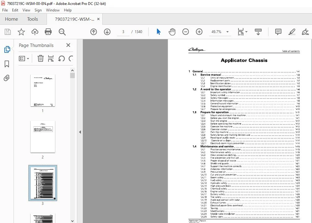
TABLE OF CONTENTS:
Challenger EU Applicators RG900C RG1100C RG1300C RoGator Chassis Workshop Service Manual – PDF DOWNLOAD
1 General 1-1
1 1 Service manual 1-3
1 1 1 Units of measurement 1-3
1 1 2 Replacement parts 1-3
1 1 3 Identification plates 1-3
1 1 4 Engine identification 1-5
1 2 A word to the operator 1-6
1 2 1 Important safety information 1-6
1 2 2 Safety symbol 1-7
1 2 3 Safety messages 1-8
1 2 4 Information messages 1-8
1 2 5 General hazard information 1-8
1 2 6 Protective equipment 1-10
1 2 7 Prepare for emergencies 1-10
1 3 Prepare for operation 1-11
1 3 1 Mount and dismount the machine 1-1 1
1 3 2 Before you start the engine 1-1 1
1 3 3 Start the engine 1-1 2
1 3 4 Before operating the machine 1-1 2
1 3 5 Operate the machine 1-1 2
1 3 6 Operator station 1-1 3
1 3 7 Park the machine 1-1 3
1 3 8 Safety lamps and marking devices use 1-1 4
1 3 9 Roading on public roads 1-1 4
1 3 10 Operate on a slope 1-1 4
1 3 1 1 Electrical storm injury prevention 1-1 4
1 4 Maintenance and service 1-15
1 4 1 Practice correct maintenance 1-1 5
1 4 2 Maintenance safety 1-1 6
1 4 3 Wear protective clothing 1-20
1 4 4 Fire prevention and first aid 1-20
1 4 5 Proper disposal of waste 1-21
1 4 6 Shield and guards 1-21
1 4 7 Support the machine correctly 1-22
1 4 8 Asbestos information 1-22
1 4 9 Pressurized air 1-22
1 4 10 Cut and crush prevention 1-22
1 4 1 1 Boom safety 1-23
1 4 1 2 Fuel safety 1-23
1 4 1 3 Hydraulic safety 1-23
1 4 1 4 High pressure leaks 1-24
1 4 1 5 Chemical safety 1-24
1 4 1 6 Engine safety 1-27
1 4 1 7 Battery safety 1-28
1 4 1 8 T ire safety 1-29
1 4 1 9 Avoid eye contact with radar 1-30
1 4 20 Exhaust fumes 1-30
1 4 21 Electrical power lines overhead 1-30
1 4 22 Towing 1-3 1
1 4 23 Modifications 1-3 1
1 4 24 Mobile radio installation 1-3 1
1 4 25 Safety signs 1-3 1
Applicator Chassis
79037219C
Table of contents
1 4 2 6 Safety and informational signs 1-3 1
1 5 Tightening specifications 1-33
1 5 1 Constant torque hose clamp 1-3 3
1 5 2 Fastener tightening specifications 1-3 3
1 5 3 Metric fasteners 1-3 5
1 5 4 Inch fasteners 1-3 7
1 5 5 Conversion table 1-4 1
2 Engine, fuel, and exhaust system 2-1
2 1 Introduction 2-9
2 1 1 Specifications and standards 2-9
2 1 2 Fuel quality requirements 2-9
2 1 3 Coolant quality requirements 2-10
2 1 4 Oil quality 2-1 1
2 1 5 Engine oil type 2-1 1
2 1 6 Engine specification 2-1 2
2 1 7 Lifting and storage 2-1 3
2 2 Engine system 2-14
2 2 1 Engine components 2-1 4
2 2 2 Remove the cooling package 2-1 8
2 2 3 Disassemble the cooling package 2-2 4
2 2 4 Assemble the cooling package 2-2 9
2 2 5 Install the cooling package 2-3 4
2 2 6 Remove the main serpentine belt 2-3 9
2 2 7 Install the main serpentine belt 2-4 1
2 2 8 Remove an alternator 2-4 2
2 2 9 Install an alternator 2-4 4
2 2 10 Remove a starter 2-4 4
2 2 1 1 Install a starter 2-4 5
2 2 1 2 Remove the fan 2-4 6
2 2 1 3 Install the fan 2-4 7
2 2 1 4 Remove the air filter assembly 2-48
2 2 1 5 Install the air filter assembly 2-5 2
2 2 1 6 Remove the air filters 2-5 6
2 2 1 7 Install the air filters 2-5 7
2 2 1 8 Remov the diesel exhaust fluid 2-5 8
2 2 1 9 Install the diesel exhaust fluid 2-6 6
2 2 20 Remove the engine 2-75
2 2 2 1 Install the engine 2-86
2 2 2 2 Remove the engine mounts 2-96
2 2 2 3 Install the engine mounts 2-97
2 2 2 4 Change the engine oil and filter 2-98
2 3 Safety instructions 2-100
2 4 To the user 2-102
2 4 1 Engine type designations 2-102
2 4 2 Location of the engine serial number 2-103
2 4 3 Marking of the electronic control unit 2-104
2 4 4 Engine lifting 2-104
2 5 Engine construction 2-106
2 5 1 Technical data 2-106
2 5 1 1 Principal dimensions and data 2-106
2 5 1 2 Fuel system 2-106
2 5 1 3 Lubrication system 2-106
2 5 1 4 Cooling system 2-107
2 5 1 5 SCR system technical data 2-107
2 5 2 Cylinder block 2-107
2 5 3 Flywheel housing 2-108
Applicator Chassis
79037219C
2 6
2 7
2 8
2 9
2 5 4
2 5 5
2 5 6
2 5 7
2 5 8
2 5 9
Table of contents
Valve mechanism 2-10 8
Cylinder head 2-10 8
Crank mechanism 2-10 8
Timing gears 2-10 9
Lubrication system 2-110
2 5 8 1 Oil pressure regulating valve 2-111
2 5 8 2 Oil filter and oil cooler 2-111
2 5 8 3 Oil filter and oil cooler 2-11 2
Cooling system 2-11 2
2 5 9 1 Thermostat 2-11 3
2 5 10 Air control system 2-114
2 5 10 1 Turbocharging 2-115
2 5 10 2 2 stage turbocharging 2-115
2 5 10 3 Cooling of inlet air 2-115
2 5 10 4 Interstage charge air cooling 2-115
2 5 10 5 Throttle valve 2-115
2 5 11 Fuel system 2-116
2 5 1 2 SCR system 2-117
2 5 1 2 1 SCR system overview 2-117
2 5 1 2 2 SCR system components and their functions 2-118
2 5 1 2 3 Supply module connectors and filters 2-1 1 9
2 5 1 2 4 Dosing module connections 2-1 1 9
2 5 1 3 Engine control system 2-1 2 0
Technical data 2-121
2 6 1 Cylinder block 2-1 2 1
2 6 2 Cylinder liners 2-1 2 1
2 6 3 Cylinder head 2-1 2 2
2 6 4 Valves and rockers 2-1 2 3
2 6 5 Tappets and push rods 2-1 24
2 6 6 Camshaft 2-1 24
2 6 7 Crankshaft 2-1 25
2 6 8 Flywheel 2-1 2 8
2 6 9 Timing gears 2-1 2 8
2 6 10 Connecting rod 2-1 2 9
2 6 11 Piston, rings and pin 2-1 30
2 6 1 2 Lubrication system 2-1 3 2
2 6 1 3 Oil pump 2-1 3 2
2 6 14 Thermostat 2-1 3 3
2 6 15 Turbocharger 2-1 3 3
Tightening torques 2-134
Special tools 2-136
2 8 1 Cylinder block tools 2-1 36
2 8 2 Timing gear and flywheel housing tools 2-1 3 9
2 8 3 Cylinder head and valve mechanism tools 2-14 1
2 8 4 Crank mechanism tools 2-14 3
2 8 5 Coolant pump tools 2-145
2 8 6 Fuel system tools 2-146
2 8 7 SCR system tools 2-15 1
2 8 8 Electronic diagnostic tool 2-15 2
2 8 8 1 EDT diagnostic terminal 2-15 3
2 8 8 2 Diagnostic terminal components 2-15 3
Liquid quality requirements 2-155
2 9 1 Lubricating oil quality requirements 2-15 5
2 9 2 Coolant quality requirements 2-15 5
2 9 3 Fuel quality requirements 2-15 6
2 9 3 1 Biodiesel blends 2-15 7
2 9 3 2 Engine output depending on fuel quality 2-15 9
Applicator Chassis
79037219C
Table of contents
2 10 Terminal diagram 2-160
2 11 Cylinder block 2-164
2 1 1 1 Measure the cylinder liner wear 2-1 6 4
2 1 1 2 Remove the cylinder liner 2-1 6 4
2 1 1 3 Do a check for the cylinder block 2-1 6 4
2 1 1 4 Changing camshaft bushing 2-1 6 5
2 1 1 5 Fitting plug at camshaft rear end 2-1 6 6
2 1 1 6 Oversize bushings for camshaft 2-1 6 6
2 1 1 7 Fitting plug at camshaft rear end (oversize bushings) 2-1 6 6
2 1 1 8 Install the cylinder liner 2-1 6 7
2 1 1 9 Remove the block heater 2-1 6 9
2 1 1 10 Install the block heater 2-1 6 9
2 12 Flywheel housing 2-170
2 1 2 1 Remove the flywheel housing 2-1 70
2 1 2 2 Install the flywheel housing 2-1 70
2 1 2 3 Changing crankshaft rear oil seal 2-1 71
2 13 Cylinder head 2-172
2 1 3 1 Removing cylinder head 2-1 72
2 1 3 2 Removing valves 2-1 72
2 1 3 3 Do a check for the cylinder head 2-1 72
2 1 3 4 Replace the valve guides 2-1 74
2 1 3 5 Machine the valve seat 2-1 74
2 1 3 6 Replace the valve seat rings 2-1 74
2 1 3 7 Grinding valves 2-1 75
2 1 3 8 Fitting valves 2-1 76
2 1 3 9 Install the cylinder head 2-1 76
2 14 Valve mechanism with hydraulic lash adjustment 2-178
2 1 4 1 How to recognize an engine with hydraulic lash adjusters 2-1 78
2 1 4 2 Remove the valve cover 2-1 79
2 1 4 3 Install the valve cover 2-1 79
2 1 4 4 Pre-adjustment of the hydraulic lash adjusters 2-1 79
2 1 4 5 Reconditioning the valve mechanism 2-1 79
2 1 4 6 Compressing the oil out from the hydraulic lash adjusters 2-1 80
2 1 4 7 Assembling the valve mechanism with the hydraulic lash adjusters 2-1 81
2 1 4 8 Pre-adjusting the hydraulic lash adjusters 2-1 82
2 1 4 9 Changing camshaft or camshaft gear 2-1 84
2 15 Crankshaft 2-185
2 1 5 1 Removing the crankshaft 2-1 85
2 1 5 2 Checking crankshaft 2-1 85
2 1 5 3 Replace the crankshaft gears 2-1 86
2 1 5 4 Installing the crankshaft 2-1 86
2 1 5 5 Crankshaft hub piece 2-1 87
2 1 5 6 Viscose type vibration damper 2-1 88
2 16 Connecting rods and pistons 2-189
2 1 6 1 Removing pistons together with connecting rods 2-1 89
2 1 6 2 Changing connecting rod bearings 2-1 89
2 1 6 2 1 Piston pin bushing 2-1 89
2 1 6 2 2 Big-end bearing 2-1 90
2 1 6 3 Checking connecting rod 2-1 91
2 1 6 4 Replace the piston rings 2-1 91
2 1 6 5 Checking pistons 2-1 92
2 1 6 6 Install the piston pin 2-1 93
2 1 6 7 Install the piston together with the connecting rod 2-1 93
2 17 Flywheel 2-195
2 1 7 1 Changing starter ring gear on flywheel 2-1 95
2 1 7 2 Remove the flywheel 2-1 95
2 1 7 3 Fitting flywheel 2-1 95
Timing gear assembly 2-196
2 18 1 Removing timing gear casing 2-196
2 18 2 Install the timing gear housing 2-197
2 18 3 Remove the hub nut of the crankshaft and the crankshaft hub 2-199
2 18 4 Install the crankshaft hub and the hub nut of the crankshaft 2-200
2 18 5 Power take-off 2-20 1
2 18 6 Fan drive device 2-20 1
Lubrication system 2-202
2 19 1 Oil pressure regulating valve 2-20 2
2 19 2 Remove the oil sump 2-20 2
2 19 3 Remove the suction pipe of the oil pump 2-20 2
2 19 4 Install the suction pipe of the oil pump 2-203
2 19 5 Removing and dismantling lubricating oil pump 2-204
2 19 6 Assembling and fitting lubricating oil pump 2-204
2 19 7 Install the oil sump gasket 2-205
2 19 7 1 Install the oil sump gasket, metal gasket 2-205
2 19 7 2 Install the oil sump gasket, paper gasket 2-205
2 19 7 3 Install the oil sump gasket, cork gasket 2-206
Install the oil sump, self-carrying oil sump and cast oil sump 2-206
Install the oil sump, stamped steel oil sump 2-208
Piston cooling nozzles 2-208
Lubricating oil cooler 2-209
Removing the oil cooler 2-2 10
Fitting the oil cooler 2-2 10
Remove the oil filter adapter 2-2 1 1
Install the oil filter adapter 2-2 1 2
Oil sump capacity 2-2 1 2
Closed crankcase ventilation 2-2 1 2
2 19 1 7 1 Remove the closed crankcase ventilation system components 2-2 13
2 19 1 7 2 Installing the closed crankcase ventilation system components 2-2 13
2 19 1 7 3 Installing the closed crankcase ventilation system components 2-2 13
Cooling system 2-215
2 20 1 Remove the distribution pipe of the coolant 2-2 15
2 20 2 Install the distribution pipe of the coolant 2-2 15
2 20 3 Removing the thermostat 2-2 16
2 20 4 Testing the thermostat 2-2 16
2 20 5 Replace the thermostat 2-2 16
2 20 6 Remove the coolant pump and the thermostat housing 2-2 16
2 20 7 Install the coolant pump and the thermostat housing 2-2 17
2 20 8 Reconditioning coolant pump 2-2 17
2 20 8 1 Coolant pumps with standard bearings 2-2 17
2 20 8 2 Coolant pumps with heavy duty bearings 2-2 20
2 20 9 Installing the cylinder head connection part 2-2 20
2 20 10 Remove the idler pulleys, the belt tightener and the belt pulley 2-2 2 1
2 20 1 1 Install the idler pulleys, the belt tightener and the belt pulley 2-2 2 2
Air control system maintenance 2-223
2 2 1 1 Checking the air cleaner 2-2 23
2 2 1 2 Do a check for the inlet and exhaust pipes 2-2 23
2 2 1 3 Remove the actuator of the turbocharger 2-2 24
2 2 1 4 Install the actuator of the turbocharger 2-2 24
2 2 1 5 Remove the exhaust manifold and the turbochargers 2-2 25
2 2 1 6 Removing the turbocharger 2-2 26
2 2 1 7 Checking the turbocharger 2-2 26
2 2 1 8 Install the high-pressure turbocharger 2-2 27
2 2 1 9 Install the exhaust manifold and the turbochargers 2-2 27
2 2 1 10 Remove the ICAC 2-2 29
2 2 1 1 1 Install the ICAC 2-2 29
Applicator Chassis
79037219C
Table of contents
2 2 1 1 2 R emove the intake manifold 2-2 30
2 2 1 1 3 Install the intake manifold 2-2 30
2 22 Fuel system 2-231
2 2 2 1 Bleed the fuel system 2-2 3 1
2 2 2 2 Measuring fuel feed pressure 2-2 3 1
2 2 2 3 R emove the fuel filters 2-2 3 2
2 2 2 4 Install the fuel filters 2-2 3 2
2 2 2 5 R emove the injector overflow pipe 2-2 3 3
2 2 2 6 Install the injector overflow pipe 2-2 3 3
2 2 2 7 Inspecting injectors 2-2 3 3
2 2 2 7 1 R emove the injectors (CR IN3) 2-2 34
2 2 2 7 2 Install the injectors (CR IN3) 2-2 35
2 2 2 8 High-pressure pump 2-2 3 7
2 2 2 8 1 R emove the high-pressure pump 2-2 3 7
2 2 2 8 2 Install the high-pressure pump 2-2 3 7
2 2 2 9 R ail 2-2 38
2 2 2 9 1 R emoving the rail 2-2 3 9
2 2 2 9 2 Install the rail 2-240
2 2 2 9 3 R emoving the pressure control valve 2-240
2 2 2 9 4 Fitting the pressure control valve 2-24 1
2 2 2 9 5 R emoving the pressure sensor 2-24 1
2 2 2 9 6 Fitting the pressure sensor 2-24 1
2 2 2 10 Troubleshooting of the Common rail fuel system 2-24 1
2 2 2 10 1 Testing the suction pressure between the fuel tank and the fuel prefilter
2-24 1
2 2 2 10 2 Testing the suction pressure between the fuel pre-filter and the feed
pump 2-2 4 3
2 2 2 10 3 Testing the feed pressure between the feed pump and the fuel main
filter 2-245
2 2 2 10 4 Testing the feed pressure between the main fuel filter and the highpressure
pump 2-246
2 2 2 10 5 Testing the total return quantity from the injectors 2-247
2 2 2 10 6 Testing the return quantity from the injectors 2-249
2 2 2 10 7 Testing the pressure control valve leakage 2-25 4
2 2 2 10 8 Testing the pressure release valve leakage 2-25 6
2 2 2 10 9 Testing the return line pressure 2-25 9
2 23 SCR system 2-260
2 2 3 1 SCR system maintenance 2-260
2 2 3 2 Mounting of SCR system components 2-260
2 2 3 3 R emoving the supply module 2-2 6 1
2 2 3 4 Installing the supply module 2-2 6 1
2 2 3 5 R emoving the hydraulic connectors 2-26 2
2 2 3 6 Installing the hydraulic connectors 2-26 2
2 2 3 7 R eplace the main filter and the inlet filter of the supply module 2-26 2
2 2 3 8 SPN 5 2 10 0 8 FMI 1 2-2 6 3
2 2 3 8 1 Solve the DEF pressure build-up failure 2-264
2 2 3 8 2 Supply module lifting capacity test 2-266
2 2 3 8 3 Solve the failure when the SM lifting capacity test is not OK 2-2 6 7
2 2 3 8 4 Solving the failure when the SM lifting capacity test is OK 2-2 6 9
2 2 3 9 SPN 5 2 10 25 FMI 3 1, SPN 5 2 10 26 FMI 3 1 2-2 7 0
2 2 3 9 1 Cleanup of the SCR catalyst 2-2 7 2
2 2 3 9 2 Make the dosing rate test 2-2 7 3
2 2 3 9 3 Checking the quality of DEF 2-2 7 7
2 24 Engine control system 2-279
2 24 1 R emove the bracket of the electronic control unit 2-2 7 9
2 24 2 Install the bracket of the electronic control unit 2-2 7 9
2 24 3 R emove the electronic control unit 2-2 7 9
2 24 4 Install the electronic control unit 2-2 7 9
R eplace the electronic control unit 2-2 80
R eplace an empty electronic control unit (ECU) 2-2 8 1
Wiring sets 2-2 8 1
2 24 7 1 Injector wiring sets 2-2 8 2
2 24 7 2 Sensor and actuator wiring sets 2-2 8 3
2 24 7 3 Wiring set for intake air heater 2-2 8 3
2 24 7 4 Sensors of the engine control system 2-2 8 3
2 24 8 R emove the wiring harnesses 2-2 86
2 24 9 Install the wiring harnesses 2-2 8 7
Prepare the long block replacement 2-289
Parts for the long block replacement 2-290
2 26 1 Delivery content of the long block engine 2-2 90
2 26 2 The parts that must be removed from the old engine 2-2 90
2 26 3 Other parts of the long block replacement 2-2 9 1
Remove the engine 2-292
Engine lifting 2-293
2 2 8 1 Lift the engine 2-2 9 3
Disassemble the engine 2-295
2 2 9 1 R emove the wiring harnesses 2-2 95
2 2 9 2 R emove the electronic control unit 2-2 95
2 2 9 3 R emove the bracket of the electronic control unit 2-2 96
2 2 9 4 R emove the exhaust manifold and the turbochargers 2-2 96
2 2 9 5 R emoving the EGR system 2-2 9 7
2 2 9 6 Change oil filter 2-2 9 7
2 2 9 7 R emoving the oil cooler 2-2 9 7
2 2 9 8 R emove the oil filter adapter 2-2 9 8
2 2 9 9 R emove the ICAC 2-2 9 8
2 2 9 10 R emove the distribution pipe of the coolant 2-2 9 9
2 2 9 11 R emove the fuel filters 2-300
2 2 9 1 2 R emove the closed crankcase ventilation system components 2-300
2 2 9 1 3 R emoving the rail 2-300
2 2 9 14 R emove the high-pressure pump 2-301
2 2 9 15 R emove the block heater 2-301
2 2 9 16 R emove the intake manifold 2-301
2 2 9 17 R emove the coolant pump and the thermostat housing 2-30 2
2 2 9 1 8 R emove the idler pulleys, the belt tightener and the belt pulley 2-30 2
2 2 9 1 9 R emove the valve cover 2-30 2
2 2 9 20 R emove the injectors (CR IN3) 2-30 3
2 2 9 20 1 R emove the injector overflow pipe 2-304
2 2 9 2 1 R emove the flywheel 2-305
2 2 9 2 2 R emove the oil sump 2-305
2 2 9 2 3 R emove the suction pipe of the oil pump 2-305
2 2 9 24 R emove the flywheel housing 2-305
Assemble the engine 2-306
2 30 1 Prepare the new long block 2-306
2 30 2 Install the flywheel housing 2-306
2 30 3 Changing crankshaft rear oil seal 2-30 7
2 30 4 Install the suction pipe of the oil pump 2-30 8
2 30 5 Install the oil sump gasket 2-30 9
2 30 6
2 30 7
2 30 8
2 30 9
2 30 10
2 30 5 1 Install the oil sump gasket, metal gasket 2-30 9
2 30 5 2 Install the oil sump gasket, paper gasket 2-30 9
2 30 5 3 Install the oil sump gasket, cork gasket 2-30 9
Install the oil sump, self-carrying oil sump and cast oil sump 2-3 10
Install the oil sump, stamped steel oil sump 2-3 11
Fitting flywheel 2-3 1 2
Install the high-pressure pump 2-3 1 2
Install the rail 2-3 1 3
Applicator Chassis
79037219C
Table of contents
2 30 1 1 Installing the closed crankcase ventilation system components 2-3 1 3
2 30 1 2 Install the fuel filters 2-3 1 4
2 30 1 2 1 Install the injector overflow pipe 2-3 1 4
2 30 1 3 Install the injectors (CR I N 3) 2-3 1 5
2 30 1 4 Install the valve cover 2-3 1 6
2 30 1 5 Install the idler pulleys , the belt tightener and the belt pulley 2-3 1 6
2 30 1 6 Install the intake manifold 2-3 1 6
2 30 1 7 Install the coolant pump and the thermostat housing 2-3 1 7
2 30 1 8 Install the block heater 2-3 1 7
2 30 1 9 Install the distribution pipe of the coolant 2-3 1 8
2 30 20 Install the IC AC 2-3 1 8
2 30 2 1 Install the oil filter adapter 2-3 1 9
2 30 2 2 Fitting the oil cooler 2-3 1 9
2 30 2 3 Change oil filter 2-3 1 9
2 30 2 4 Fitting the E GR system 2-3 20
2 30 2 5 Install the e xhaust manifold and the turbochargers 2-3 20
2 30 2 6 Install the electronic control unit 2-3 2 2
2 30 2 7 Install the bracket of the electronic control unit 2-3 2 2
2 30 2 8 Install the wiring harnesses 2-3 2 2
2 31 Engine lifting 2-32 4
2 3 1 1 Lift the engine 2-3 2 4
2 32 Install the engine 2-326
2 33 After the long block change 2-327
2 3 3 1 Starting the engine after major maintenance 2-3 2 7
2 3 3 2 Update the engine software 2-3 2 7
2 3 3 3 Break in the engine 2-3 2 7
2 34 Fuel system 2-329
2 3 4 1 Backflush fuel filter water separator 2-3 2 9
2 3 4 2 Operate the fuel priming pump 2-3 3 1
2 3 4 3 Remove the right fuel tank 2-3 3 3
2 3 4 4 Remove the left fuel tank 2-3 3 6
2 3 4 5 Disassemble the fuel tanks 2-3 40
2 3 4 6 Assemble the fuel tanks 2-3 4 1
2 3 4 7 Install the right fuel tank 2-3 4 2
2 3 4 8 Install the left fuel tank 2-3 4 5
2 3 4 9 Remove the tank for the diesel e xhaust fluid 2-3 4 9
2 3 4 10 Disassemble the diesel e xhaust fluid tank 2-3 5 1
2 3 4 1 1 Assemble the diesel e xhaust fluid tank 2-3 5 2
2 3 4 1 2 Install the tank for the diesel e xhaust fluid 2-3 5 3
2 3 4 1 3 Replace the sensor for the fuel tank 2-3 5 5
2 3 4 1 4 Remove the primary fuel filter 2-3 6 5
2 3 4 1 5 Install the primary fuel filter 2-3 6 6
2 3 4 1 6 Remove the secondary fuel filter 2-3 6 7
2 3 4 1 7 Install the secondary fuel filter 2-3 6 8
2 3 4 1 8 Remove the fuel filter water separator 2-3 6 9
2 3 4 1 9 Install the fuel filter water separator 2-3 71
2 3 4 20 Check and tighten the fuel tank bolts 2-3 72
2 35 Exhaust system 2-373
2 3 5 1 Removing the e xhaust system without diesel e xhaust fluid 2-3 73
2 3 5 2 Install the e xhaust system without diesel e xhaust fluid 2-3 75
2 35 3 Remove the e xhaust system with diesel e xhaust fluid 2-3 78
2 35 4 Install the e xhaust system with diesel e xhaust fluid 2-3 83
2 35 5 Remove the supply module 2-3 88
2 3 5 6 Install the supply module 2-3 89
2 35 7 Remove the D E F filter 2-3 90
2 3 5 8 Install the D E F filter 2-3 91
2 3 5 9 Remove the dosing module 2-3 92
Applicator Chassis
79037219C
2 35 10
2 35 11
2 35 1 2
2 35 1 3
2 35 14
2 35 15
2 35 16
2 35 17
2 35 1 8
Table o f contents
Install the dosing module 2-3 9 3
R emove an exhaust gas temperature sensor 2-3 9 3
Install an exhaust gas temperature sensor 2-3 94
R emove a NO x sensor 2-3 94
Install a NO x sensor 2-395
R emove the D EF sensor 2-396
Install the D EF sensor 2-3 9 8
SCR system 2-3 9 9
SCR components 2-401
3 Axl es 3- 1
3 1 Axl e component introduction 3-3
3 2 Front axle introduction 3-6
3 2 1 R emove the front wheel leg 3-6
3 2 2 R emove the steerable axle weldment 3-11
3 2 3 R emove the front axle weldment 3-15
3 2 4 Install the front axle weldment 3-2 1
3 2 5 Install the steerable axle weldment 3-2 8
3 2 6 Install the front wheel leg 3-3 3
3 3 Rear axl e introduction 3-39
3 3 1 R emove the rear wheel leg 3-3 9
3 3 2 R emove the rear 4 wheel steer wheel leg 3-45
3 3 3 R emove the rear steerable axle weldment 3-5 0
3 3 4 R emove the rear axle weldment 3-5 4
3 3 5 Install the rear axle weldment 3-6 3
3 3 6 Install the rear steerable axle weldment 3-7 2
3 3 7 Install the rear 4 wheel steer wheel leg 3-7 7
3 3 8 Install the rear wheel leg 3-8 2
3 4 Maintenance and service 3-88
3 4 1 Adjust an axle wear pad 3-8 8
3 4 2 Apply grease to the axle lubrication fittings 3-8 8
3 4 3 Adjust the manual track width 3-8 9
3 4 4 Calibrate the Auto Track 3-90
4 Frame and suspension 4- 1
4 1 Frame and suspension introduction 4-3
4 2 Air spring removal 4-4
4 2 1 R emove the front axle air spring 4-4
4 2 2 R emove the rear axle air spring 4-5
4 3 Air spring installation 4-8
4 3 1 Install the front axle air spring 4-8
4 3 2 Install the rear axle air spring 4-9
4 4 Adjust the ride height 4- 1 1
5 Steering system 5- 1
5 1 Steering system introduction 5-3
5 2 Steering system components 5-4
5 2 1 R emove the steering pump 5-4
5 2 2 D isassemble the steering pump 5-5
5 2 3 Assemble the steering pump 5-6
5 2 4 Install the steering pump 5-7
5 2 5 R emove the steering unit 5-9
5 2 6 R emove the steering angle sensor 5-10
5 2 7 Install the steering angle sensor 5-10
5 2 8 Install the steering unit 5-11
5 2 9 R emoving the front steering cylinder 5-1 2
Applicator Chassis
79037219C
Table of contents
5 2 10 Disassemble a cylinder 5-1 4
5 2 1 1 Assemble a cylinder 5-1 7
5 2 1 2 Install the front steering cylinder 5-2 1
5 2 1 3 Remove the rear steering cylinder 5-2 4
5 2 1 4 Install the rear steering cylinder 5-2 5
5 3 Steering system adjustments 5-28
5 3 1 Bleed air from the steering cylinder 5-2 8
5 3 2 Adjust the toe-in 5-2 8
5 3 3 Adjust the four wheel steer toe-in 5-2 9
5 3 4 Calibrate the steering angle sensor 5-3 4
5 3 5 Calibrate the steering valve 5-3 5
5 3 6 Adjust the steering pump pressure 5-3 6
6 Drive train system 6-1
6 1 Drive train system introduction 6-3
6 2 Drive train system components 6-4
6 2 1 Remove the pump drive components 6-4
6 2 2 Install the pump drive components 6-5
6 2 3 Remove the wheel drive gearbo x 6-7
6 2 4 Install the wheel drive gearbo x 6-9
6 3 Wheel drive gearbox service information 6-12
6 3 1 Wheel drive gearbo x lubrication 6-1 2
6 3 2 Fill the wheel drive gearbo x 6-1 2
6 3 3 Initial start-up and operation of wheel drive gearbo x 6-1 3
6 3 4 Wheel motor gearbo x maintenance information 6-1 3
6 3 5 Wheel drive gearbo x maintenance schedule 6-1 3
6 3 6 Drain and replace the oil 6-1 4
6 3 7 Wheel drive gearbo x troubleshooting 6-1 4
7 Brake system 7-1
7 1 Brake system introduction 7-3
7 2 Brake system components 7-4
7 2 1 Remove the park brake-ladder valve 7-4
7 2 2 Install the park brake-ladder valve 7-6
7 2 3 Brake release if equipped 7-8
7 2 4 Remove the service brake valve 7-8
7 2 5 Install the service brake valve 7-10
7 2 6 Remove the brake caliper 7-1 2
7 2 7 Install the brake caliper 7-1 3
7 2 8 Remove the brake accumulator 7-1 4
7 2 9 Install the brake accumulator 7-1 5
7 2 10 Remove the brake rotor 7-1 7
7 2 1 1 Install the brake rotor 7-1 7
7 3 Brake system test and adjust 7-19
7 3 1 Check the service brake pressure 7-1 9
7 3 2 Check the park brake pressure 7-1 9
7 3 3 Calibrate the brake pedal 7-20
8 Air system 8-1
8 1 Air system options 8-3
8 1 1 Standard air system component layout 8-3
8 1 2 High volume air system component layout 8-4
8 2 Air system components 8-5
8 2 1 Remove the air compressor 8-5
8 2 2 Install the air compressor 8-8
8 2 3 Remove the air dryer 8-10
Applicator Chassis
79037219C
8 2 4
8 2 5
8 2 6
8 2 7
8 2 8
8 2 9
8 2 10
8 2 11
8 2 1 2
8 2 1 3
8 2 14
8 2 15
8 2 16
8 2 17
8 2 1 8
8 2 1 9
8 2 20
8 2 2 1
Table of contents
Install the air dryer 8-1 2
R emove the air reservoir 8-14
Install the air reservoir 8-16
R emove the rear ride height control valve 8-1 8
Install the rear ride height control valve 8-2 0
R emove the front ride height control valve 8-2 2
Install the front ride height control valve 8-24
Adjust the ride height 8-26
R emove the air governor 8-2 7
Install the air governor 8-2 8
R emove the air pressure regulator 8-2 9
Install the air pressure regulator 8-3 1
R emove the cab air ride suspension 8-3 3
Install the cab air ride suspension 8-35
R emovie the air dump valve 8-3 7
Install the air dump valve 8-3 9
R emove the air pressure transducer 8-40
Install the air pressure transducer 8-4 2
9 Hydraulic system 9- 1
9 1 Hydraulic system introduction 9-3
9 2 Hydraulic system components 9-6
9 2 1 Hydrostatic drive pump 9-6
9 2 2 Charge pump 9-8
9 2 3 Hydraulic reservoir 9-9
9 2 4 Ladder cylinder 9-10
9 2 5 Service brake valve 9-10
9 2 6 Standard steering pump 9-11
9 2 7 Cold start steering pump 9-1 3
9 2 8 Pressure washer control valve, if equipped 9-14
9 2 9 Pressure washer pump/motor, if equipped 9-15
9 2 10 Priority valve 9-16
9 2 11 R eturn filter manifold 9-17
9 2 1 2 Park brake -ladder valve 9-17
9 2 1 3 Drive manifold 9-1 8
9 2 14 Front steering cylinders 9-1 8
9 2 15 R ear steering cylinders, if equipped 9-1 9
9 2 16 Steering unit 9-1 9
9 2 17 Four-wheel steer control valve 9-20
9 2 1 8 Steering angle sensor if equipped 9-20
9 2 1 9 Track adjust cylinders, if equipped 9-20
9 2 20 Wheel motor 9-2 2
9 2 2 1 Wheel drive gearbox 9-2 2
9 2 2 2 Brake caliper 9-2 3
9 2 2 3 Hydraulic oil cooler 9-2 3
9 3 Hydraulic system disassembly and assembly 9-24
9 3 1 R emove the hydraulic tank 9-24
9 3 2 Fill the wheel drive gearbox 9-2 7
9 3 3 Disassemble the hydraulic tank 9-2 7
9 3 4 Assemble the hydraulic tank 9-2 9
9 3 5 R eplace the oil level sensor for the hydraulic tank 9-30
9 3 6 Install the hydraulic tank 9-3 1
9 3 7 R emove the system hydraulic pump 9-34
9 3 8 Install the system hydraulic pump 9-36
9 3 9 R emove the steering pump 9-3 7
9 3 10 Disassemble the steering pump 9-38
9 3 11 Assemble the steering pump 9-3 9
9 3 1 2 Install the steering pump 9-4 1
Applicator Chassis
79037219C
Table of contents
9 3 1 3 R emove the hydrostatic drive pump 9-4 2
9 3 14 R eplace the bearing and shaft 9-45
9 3 15 R eplace the ex ternal filter 9-46
9 3 16 Service the filter by-pass valve 9-46
9 3 17 Service the high pressure relief valve 9-47
9 3 1 8 Service the charge pressure relief valve 9-47
9 3 1 9 R eplace the pressure limiter valve 9-47
9 3 20 R eplace the charge pump 9-48
9 3 2 1 Install the hydrostatic drive pump 9-5 0
9 3 2 2 Hydrostatic drive pump start-up procedure 9-5 3
9 3 2 3 R emove the ladder cylinder 9-5 5
9 3 24 R emove the priority valve 9-5 9
9 3 25 Install the priority valve 9-60
9 3 26 R emove the filter manifold 9-6 1
9 3 2 7 Install the filter manifold 9-6 3
9 3 2 8 R emove the park brake-ladder valve 9-65
9 3 2 9 Install the park brake-ladder valve 9-6 7
9 3 30 R emove the track adjust cylinder 9-6 9
9 3 3 1 Disassemble a cylinder 9-7 0
9 3 3 2 Assemble a cylinder 9-7 4
9 3 3 3 Install the trac k adjust cylinder 9-7 7
9 3 34 R emove the rear track adjust cylinder 9-80
9 3 35 Install the rear track adjust cylinder 9-8 1
9 3 36 R emove the front track adjust valve 9-84
9 3 3 7 Install the front track adjust valve 9-86
9 3 38 R emove the rear track adjust valve 9-8 9
9 3 3 9 Install the rear track adjust valve 9-9 1
9 3 40 R emove the wheel motor 9-95
9 3 4 1 Install the wheel motor 9-9 7
9 3 4 2 R emove the hydraulic oil cooler 9-100
9 3 4 3 Install the hydraulic oil cooler 9-10 3
9 4 Hydraulic system maintenance 9- 1 06
9 4 1 Hydrostatic system general test and adjust information 9-106
9 4 2 Hydraulic system test ports 9-106
9 4 3 R eturn filter manifold check valves 9-10 8
9 4 4 R eplace the pressure switch in the return filter manifold 9-10 8
9 4 5 R eplace the temperature switc h in the return filter manifold 9-10 9
9 4 6 Bleed air from the steering cylinder 9-10 9
9 4 7 Adjust the toe-in 9-110
9 4 8 Adjust the four wheel steer toe-in 9-111
9 4 9 R eplace a track valve solenoid 9-115
9 4 10 R eplace the check valve 9-117
9 4 11 R eplace cartridge valve 9-118
9 4 1 2 Trac k adjust solenoid c hart 9-1 2 0
9 4 1 3 Adjust the charge pressure relief valve 9-1 2 1
9 4 14 R eplace the cylinder position sensor 9-1 2 1
9 4 15 Change the hydraulic oil and filters 9-1 2 3
10 Electrical system troubl eshooting 1 0- 1
10 1 General information 1 0- 1 1
10 1 1 Introduction to the electrical system 10-11
10 1 2 Basic electrical troubleshooting procedures 10-11
10 1 3 Electrical service tools 10-11
10 1 4 Test a fuse 10-1 2
10 1 5 Test a diode 10-1 2
10 1 6 Test a relay 10-1 2
10 1 7 CAN data network diagram 10-1 3
10 2 Fault codes 1 0- 1 4
Applicator Chassis
79037219C
10 2 1
10 2 2
10 2 3
10 2 4
10 2 5
10 2 6
10 2 7
10 2 8
10 2 9
10 2 10
10 2 1 1
10 2 1 2
10 2 13
10 2 14
10 2 15
10 2 16
10 2 17
10 2 18
10 2 19
10 2 20
10 2 2 1
10 2 2 2
10 2 23
10 2 24
10 2 25
10 2 26
10 2 27
10 2 28
10 2 29
10 2 30
10 2 3 1
10 2 3 2
10 2 33
10 2 34
10 2 35
10 2 36
10 2 37
10 2 38
10 2 39
10 2 40
10 2 4 1
10 2 4 2
10 2 43
10 2 44
10 2 45
10 2 46
10 2 47
10 2 48
10 2 49
10 2 50
10 2 5 1
10 2 5 2
10 2 53
10 2 54
10 2 55
10 2 56
10 2 57
10 2 58
Applicator Chassis
79037219C
Table of contents
Code 1 1 00 10-14
Code 1 1 0 1 10-14
Code 2 1 00 10-14
Code 2 1 0 1 10-14
Code 2 1 0 2 10-14
Code 2 1 03 10-14
Code 2 1 04 10-14
Code 2 1 0 D 10-14
Code 2 1 0 F 10-14
Code 2 1 1 1 10-14
Code 2 1 14 10-14
Code 2 1 18 10-14
Code 2 1 19 10-14
Code 2 1 1A 10-14
Code 2 1 1 B 10-15
Code 2 1 1 E 10-15
Code 2 1 1 F 10-15
Code 2 1 20 10-15
Code 2 1 33 10-15
Code 2 1 37 10-15
Code 2 1 4 1 10-15
Code 2 1 44 10-16
Code 2 1 46 10-16
Code 2 1 80 10-16
Code 2 1 8 1 10-16
Code 2 1 8 2 10-16
Code 2 1 83 10-16
Code 2 1 90 10-16
Code 2 1 9 1 10-16
Code 2 1 9 2 10-16
Code 2 1 98 10-16
Code 2 2 4 2 10-16
Code 2 2 43 10-17
Code 2 3 40 10-17
Code 2 3 45 10-17
Code 2 3 47 10-17
Code 3 1 00 10-18
Code 3 1 0 1 10-18
Code 3 1 0 2 10-18
Code 3 1 03 10-18
Code 3 1 07 10-18
Code 3 1 08 10-18
Code 3 1 09 10-18
Code 3 1 20 10-18
Code 3 1 30 10-18
Code 3 1 40 10-18
Code 3 1 7 F 10-18
Code 4 1 0 1 10-18
Code 4 1 0 2 10-18
Code 4 1 03 10-19
Code 4 1 04 10-19
Code 4 1 05 10-19
Code 4 1 06 10-19
Code 4 1 07 10-19
Code 4 1 08 10-19
Code 4 1 09 10-19
Code 4 1 0A 10-19
Code 4 1 0 B 10-19
Table of contents
10 2 5 9 Code 4 1 0C 10-1 9
10 2 60 Code 4 1 0 D 10-20
10 2 6 1 Code 4 1 0E 10-20
10 2 6 2 Code 4 1 0F 10-20
10 2 6 3 Code 4 1 10 10-20
10 2 64 Code 4 1 11 10-20
10 2 65 Code 4 1 1 2 10-20
10 2 66 Code 4 1 1 3 10-20
10 2 6 7 Code 4 1 14 10-20
10 2 68 Code 4 1 15 10-20
10 2 6 9 Code 4 1 16 10-2 1
10 2 7 0 Code 4 1 17 10-2 1
10 2 7 1 Code 4 1 1 8 10-2 1
10 2 7 2 Code 4 1 1 9 10-2 1
10 2 7 3 Code 4 1 1 A 10-2 1
10 2 7 4 Code 4 1 1 B 10-2 1
10 2 7 5 Code 4 1 1 C 10-2 1
10 2 7 6 Code 4 1 1 D 10-2 1
10 2 7 7 Code 4 1 1 E 10-2 1
10 2 7 8 Code 4 1 1 F 10-2 2
10 2 7 9 Code 4 1 20 10-2 2
10 2 80 Code 4 1 2 1 10-2 2
10 2 8 1 Code 4 1 2 2 10-2 2
10 2 8 2 Code 4 1 2 3 10-2 2
10 2 8 3 Code 4 1 24 10-2 2
10 2 84 Code 04 1 25 10-2 2
10 2 85 Code 04 1 26 10-2 2
10 2 86 Code 4 1 2 7 10-2 2
10 2 8 7 Code 4 1 2 8 10-2 3
10 2 8 8 Code 4 1 2 9 10-2 3
10 2 8 9 Code 4 1 2A 10-2 3
10 2 90 Code 4 1 2B 10-2 3
10 2 9 1 Code 4 0 2 C 10-2 3
10 2 9 2 Code 4 0 2 D 10-2 3
10 2 9 3 Code 4 0 2E 10-2 3
10 2 94 Code 4 1 2F 10-2 3
10 2 95 Code 4 1 30 10-2 3
10 2 96 Code 4 1 3 1 10-24
10 2 9 7 Code 4 1 3 2 10-24
10 2 9 8 Code 4 1 3 3 10-24
10 2 9 9 Code 4 1 34 10-24
10 2 100 Code 4 1 35 10-24
10 2 10 1 Code 4 1 36 10-24
10 2 10 2 Code 4 1 3 7 10-24
10 2 10 3 Code 4 1 38 10-24
10 2 104 Code 4 1 3 9 10-24
10 2 105 Code 4 1 3A 10-24
10 2 106 Code 4 1 3B 10-25
10 2 10 7 Code 4 1 3C 10-25
10 2 10 8 Code 4 1 3D 10-25
10 2 10 9 Code 4 1 3E 10-25
10 2 110 Code 4 1 3F 10-25
10 2 111 Code 4 1 40 10-25
10 2 11 2 Code 4 1 4 1 10-25
10 2 11 3 Code 4 1 4 2 10-25
10 2 114 Code 4 1 4 3 10-25
10 2 115 Code 4 1 44 10-25
10 2 116 Code 4 1 45 10-25
Applicator Chassis
79037219C
Table of contents
10 2 1 17 Code 4 1 46 10-26
10 2 1 18 Code 4 1 47 10-26
10 2 1 19 Code 4 1 48 10-26
10 2 1 20 Code 4 1 49 10-26
10 2 1 2 1 Code 4 1 4A 10-26
10 2 1 2 2 Code 4 1 4 B 10-26
10 2 1 23 Code 4 1 4C 10-26
10 2 1 24 Code 4 1 4D 10-26
10 2 1 25 Code 4 1 4 E 10-26
10 2 1 26 Code 4 1 4 F 10-27
10 2 1 27 Code 4 1 50 10-27
10 2 1 28 Code 4 1 5 1 10-27
10 2 1 29 Code 4 1 5 2 10-27
10 2 130 Code 4 1 53 10-28
10 2 13 1 Code 4 1 54 10-28
10 2 13 2 Code 4 1 55 10-28
10 2 133 Code 4 1 56 10-28
10 2 134 Code 0 D 1 00 10-28
10 2 135 Code 0 D 1 0 1 10-28
10 2 136 Code 0 D 1 0 2 10-28
10 2 137 Code 0 D 1 05 10-28
10 2 138 Code 0 D 1 06 10-28
10 2 139 Code 0 D 1 07 10-28
10 2 140 Code 0 D 1 08 10-28
10 2 14 1 Code 0 D 1 09 10-28
10 2 14 2 Code 0 D 1 0A 10-28
10 2 143 Code 0 D 1 0 B 10-28
10 2 144 Code 0 D 1 0C 10-29
10 2 145 Code 0 D 1 0 D 10-29
10 2 146 Code 0 F 1 00 10-29
10 2 147 Code 0 F 1 0 1 10-29
10 2 148 Code 0 F 1 0 2 10-29
10 2 149 Code 0 F 1 05 10-29
10 2 150 Code 0 F 1 06 10-29
10 2 15 1 Code 0 F 1 07 10-29
10 2 15 2 Code 0 F 1 08 10-29
10 2 153 Code 0 F 1 09 10-29
10 2 154 Code 0 F 1 0A 10-29
10 2 155 Code 0 F 1 0 B 10-29
10 2 156 Code 0 F 1 0C 10-29
10 2 157 Code 0 F 1 10 10-29
10 2 158 Code 0 F 1 17 10-30
10 2 159 Code 0 F 1 18 10-30
10 2 160 Code 0 F 1 1 D 10-30
10 2 16 1 Code 0 F 1 2 B 10-30
10 2 16 2 Code 1 1 1 00 10-30
10 2 163 Code 1 1 1 10 10-30
10 2 164 Code 1 1 1 1 C 10-30
10 2 165 Code 1 1 1 B0 10-30
10 2 166 Code 1 1 1 F0 10-30
10 2 167 Code 1 1 1 F 1 10-30
10 2 168 Code 1 1 1 F E 10-30
10 2 169 Code 14 1 00 10-30
10 2 170 Code 14 1 0 1 10-30
10 2 17 1 Code 18 1 0 1 10-3 1
10 2 17 2 Code 18 1 0 2 10-3 1
10 2 173 Code 18 1 04 10-3 1
10 2 174 Code 18 1 08 10-3 1
Applicator Chassis
79037219C
Table of contents
10 2 1 75 Code 1 8 1 10 10-3 1
10 2 1 76 Code 1 8 1 1 1 10-3 1
10 2 1 77 Code 1 8 1 1 2 10-3 1
10 2 1 78 Code 1 8 1 1C 10-3 1
10 2 1 79 Code 1 8 1 2 A 10-3 1
10 2 1 80 Code 1 8 1 2C 10-3 1
10 2 1 81 Code 1 8 1 30 10-3 1
10 2 1 82 Code 1 8 1 3 2 10-3 1
10 2 1 83 Code 1 8 1 3 3 10-3 2
10 2 1 84 Code 1 8 1 3 4 10-3 2
10 2 1 85 Code 1 8 1 3 6 10-3 2
10 2 1 86 Code 1 8 1 3 7 10-3 2
10 2 1 87 Code 1 8 1 3A 10-3 2
10 2 1 88 Code 1 8 1 3B 10-3 2
10 2 1 89 Code 1 8 1 3C 10-3 2
10 2 1 90 Code 1 8 1 40 10-3 2
10 2 1 91 Code 1 8 1 4A 10-3 3
10 2 1 92 Code 1 8 1 4B 10-3 3
10 2 1 93 Code 1 8 1 5C 10-3 3
10 2 1 94 Code 1 8 1 5 D 10-3 3
10 2 1 95 Code 1 8 1 6 6 10-3 3
10 2 1 96 Code 1 8 1 6 9 10-3 3
10 2 1 97 Code 1 8 1 6A 10-3 3
10 2 1 98 Code 1 8 1 6 B 10-3 3
10 2 1 99 Code 1 8 1 6C 10-3 3
10 2 200 Code 1 8 1 6 D 10-3 3
10 2 201 Code 1 8 1 70 10-3 4
10 2 202 Code 1 8 1 7F 10-3 4
10 2 203 Code 1 8 1 80 10-3 4
10 2 204 Code 1 8 1 81 10-3 4
10 2 205 Code 1 8 1 82 10-3 4
10 2 206 Code 1 8 1 83 10-3 4
10 2 207 Code 1 8 3 00 10-3 4
10 2 208 Code 1 8 3 4 1 10-3 4
10 2 209 Code 1 8 3 71 10-3 4
10 2 2 10 Code 1 8 3 72 10-3 5
10 2 2 1 1 Code 1 9 1 00 10-3 5
10 2 2 1 2 Code 1 9 1 10 10-3 5
10 2 2 1 3 Code 1 9 1 1 1 10-3 5
10 2 2 1 4 Code 1 9 1 1 2 10-3 5
10 2 2 1 5 Code 1 9 1 1 3 10-3 5
10 2 2 1 6 Code 1 9 1 1 4 10-3 5
10 2 2 1 7 Code 1 9 1 4F 10-3 5
10 2 2 1 8 Code 1 9 1 1 5 10-3 5
10 2 2 1 9 Code 1 9 1 1 6 10-3 5
10 2 2 20 Code 1 9 1 1 7 10-3 5
10 2 2 2 1 Code 1 9 1 1 8 10-3 5
10 2 2 2 2 Code 1 9 1 1 9 10-3 5
10 2 2 2 3 Code 1 9 1 1A 10-3 5
10 2 2 2 4 Code 1 9 1 1 B 10-3 6
10 2 2 2 5 Code 1 9 1 1C 10-3 6
10 2 2 2 6 Code 1 9 1 1 D 10-3 6
10 2 2 2 7 Code 1 9 1 1 E 10-3 6
10 2 2 2 8 Code 1 9 1 1 F 10-3 6
10 2 2 2 9 Code 1 9 1 20 10-3 6
10 2 2 30 Code 1 9 1 2 1 10-3 6
10 2 2 3 1 Code 1 9 1 2 2 10-3 6
10 2 2 3 2 Code 1 9 1 2 3 10-3 6
Applicator Chassis
79037219C
Table of contents
10 2 2 3 3 Code 1 9 1 24 10-36
10 2 2 34 Code 1 9 1 25 10-36
10 2 2 35 Code 1 9 1 26 10-36
10 2 2 36 Code 1 9 1 2 7 10-36
10 2 2 3 7 Code 1 9 1 2 8 10-36
10 2 2 38 Code 1 9 1 2 9 10-3 7
10 2 2 3 9 Code 1 9 1 2A 10-3 7
10 2 240 Code 1 9 1 2B 10-3 7
10 2 241 Code 1 9 1 2C 10-3 7
10 2 24 2 Code 1 9 1 2 D 10-3 7
10 2 24 3 Code 1 9 1 2E 10-3 7
10 2 244 Code 1 9 1 2F 10-3 7
10 2 245 Code 1 9 1 30 10-3 7
10 2 246 Code 1 9 1 3 1 10-3 7
10 2 247 Code 1 9 1 3 2 10-3 7
10 2 248 Code 1 9 1 3 3 10-3 7
10 2 249 Code 1 9 1 34 10-3 7
10 2 25 0 Code 1 9 1 35 10-38
10 2 25 1 Code 1 9 1 36 10-38
10 2 25 2 Code 1 9 1 3 7 10-38
10 2 25 3 Code 1 9 1 38 10-38
10 2 25 4 Code 1 9 1 3 9 10-38
10 2 25 5 Code 1 9 1 3A 10-38
10 2 25 6 Code 1 9 1 3B 10-38
10 2 25 7 Code 1 9 1 3C 10-38
10 2 25 8 Code 1 9 1 3D 10-38
10 2 25 9 Code 1 9 1 3E 10-3 9
10 2 260 Code 1 9 1 3F 10-3 9
10 2 26 1 Code 1 9 1 40 10-3 9
10 2 26 2 Code 1 9 1 4 1 10-3 9
10 2 26 3 Code 1 9 1 4 2 10-3 9
10 2 264 Code 1 9 1 4 3 10-3 9
10 2 265 Code 1 9 1 44 10-3 9
10 2 266 Code 1 9 1 45 10-3 9
10 2 267 Code 1 9 1 46 10-3 9
10 2 268 Code 1 9 1 47 10-3 9
10 2 26 9 Code 1 9 1 48 10-3 9
10 2 2 7 0 Code 1 9 1 49 10-3 9
10 2 2 7 1 Code 1 9 1 4A 10-40
10 2 2 7 2 Code 1 9 1 4B 10-4 1
10 2 2 7 3 Code 1 9 1 4C 10-4 1
10 2 2 7 4 Code 1 9 1 4D 10-4 1
10 2 2 7 5 Code 1 9 1 4E 10-4 1
10 2 2 7 6 Code 1 9 1 5 0 10-4 1
10 2 2 7 7 Code 1 9 1 5 1 10-4 1
10 2 2 7 8 Code 1 9 1 5 2 10-4 1
10 2 2 7 9 Code 1 9 1 5 3 10-4 1
10 2 2 80 Code 1 9 1 5 4 10-4 1
10 2 2 8 1 Code 1 9 1 5 5 10-4 1
10 2 2 8 2 Code 1 9 1 5 6 10-4 1
10 2 2 8 3 Code 1 9 1 5 7 10-4 1
10 2 2 84 Code 1 9 1 5 8 10-4 1
10 2 2 85 Code 1 9 1 5 9 10-4 1
10 2 2 86 Code 1 9 1 5A 10-4 2
10 2 2 8 7 Code 1 9 1 5 B 10-4 2
10 2 2 8 8 Code 1 9 1 5 C 10-4 2
10 2 2 8 9 Code 1 9 1 5 D 10-4 2
10 2 2 90 Code 1 9 1 5 E 10-4 2
Applicator Chassis
79037219C
Table of contents
10 2 2 91 Code 1 9 1 5 F 10-4 2
10 2 2 92 Code 1 9 1 60 10-4 2
10 2 2 93 Code 1 9 1 6 1 10-4 2
10 2 2 94 Code 1 9 1 6 2 10-4 2
10 2 2 95 Code 1 9 1 6 3 10-4 2
10 2 2 96 Code 1 9 1 6 4 10-4 2
10 2 2 97 Code 1 9 1 6 5 10-4 2
10 2 2 98 Code 1 9 1 6 6 10-4 2
10 2 2 99 Code 1 9 1 6 7 10-4 2
10 2 300 Code 1 9 1 6 8 10-4 3
10 2 301 Code 1 9 1 6 9 10-4 3
10 2 302 Code 1 9 1 6A 10-4 3
10 2 303 Code 1 9 1 6 B 10-4 3
10 2 304 Code 1 9 1 6C 10-4 3
10 2 305 Code 1 9 1 6 D 10-4 3
10 2 306 Code 1 9 1 6 E 10-4 3
10 2 307 Code 1 9 1 6 F 10-4 3
10 2 308 Code 1 9 1 70 10-4 3
10 2 309 Code 1 9 1 71 10-4 3
10 2 3 10 Code 1 9 1 72 10-4 3
10 2 3 1 1 Code 1 9 1 73 10-4 3
10 2 3 1 2 Code 1 9 1 74 10-4 3
10 2 3 1 3 Code 1 9 1 75 10-4 4
10 2 3 1 4 Code 1 9 1 76 10-4 4
10 2 3 1 5 Code 1 9 1 77 10-4 4
10 2 3 1 6 Code 1 9 1 78 10-4 4
10 2 3 1 7 Code 1 9 1 79 10-4 4
10 2 3 1 8 Code 1 9 1 7A 10-4 4
10 2 3 1 9 Code 1 9 1 7B 10-4 4
10 2 3 20 Code 1 9 1 7C 10-4 4
10 2 3 2 1 Code 1 9 1 7D 10-4 4
10 2 3 2 2 Code 1 9 1 7E 10-4 4
10 2 3 2 3 Code 1 9 1 7F 10-4 4
10 2 3 2 4 Code 1 9 1 80 10-4 4
10 2 3 2 5 Code 1 9 1 81 10-4 4
10 2 3 2 6 Code 1 9 1 82 10-4 4
10 2 3 2 7 Code 1 9 1 83 10-4 5
10 2 3 2 8 Code 1 9 1 84 10-4 5
10 2 3 2 9 Code 1 9 1 85 10-4 5
10 2 3 30 Code 1 9 1 86 10-4 5
10 2 3 3 1 Code 1 9 1 87 10-4 5
10 2 3 3 2 Code 1 9 1 88 10-4 5
10 2 3 3 3 Code 1 9 1 89 10-4 5
10 2 3 3 4 Code 1 9 1 8A 10-4 5
10 2 3 3 5 Code 1 9 1 8B 10-4 5
10 2 3 3 6 Code 1 9 1 8C 10-4 5
10 2 3 3 7 Code 1 9 1 8D 10-4 5
10 2 3 3 8 Code 1 9 1 8E 10-4 5
10 2 3 3 9 Code 1 9 1 8F 10-4 5
10 2 3 40 Code 1A 1 01 10-4 5
10 2 3 4 1 Code 1A 1 02 10-4 6
10 2 3 4 2 Code 1A 1 03 10-4 6
10 2 3 4 3 Code 1A 1 04 10-4 6
10 2 3 4 4 Code 1 B 1 00 10-4 6
10 2 3 4 5 Code 1 B 1 01 10-4 6
10 2 3 4 6 Code 1 B 1 02 10-4 6
10 2 3 4 7 Code 1 B 1 03 10-4 6
10 2 3 4 8 Code 1 B 1 04 10-4 6
Applicator Chassis
79037219C
Table of contents
10 2 3 4 9 Code 1 B 1 05 10-4 6
10 2 3 50 Code 1 B 1 06 10-4 6
10 2 3 5 1 Code 1 B 1 07 10-4 7
10 2 3 5 2 Code 1 B 1 08 10-4 7
10 2 3 5 3 Code 1 B 1 09 10-4 7
10 2 3 5 4 Code 1 B 1 0A 10-4 7
10 2 3 5 5 Code 1 B 1 0B 10-4 7
10 2 3 5 6 Code 1 B 1 0C 10-4 7
10 2 3 5 7 Code 1 B 1 0D 10-4 7
10 2 3 5 8 Code 1 B 1 0E 10-4 7
10 2 3 5 9 Code 1 B 1 0F 10-4 7
10 2 3 60 Code 1 B 1 10 10-4 8
10 2 3 6 1 Code 1 8 1 1 1 10-4 8
10 2 3 6 2 Code 1 B 1 1 2 10-4 8
10 2 3 6 3 Code 1 8 1 1 3 10-4 8
10 2 3 6 4 Code 1 B 1 1 4 10-4 8
10 2 3 6 5 Code 1 8 1 1 5 10-4 8
10 2 3 6 6 Code 1 8 1 1 6 10-4 8
10 2 3 6 7 Code 1 B 1 1 7 10-4 8
10 2 3 6 8 Code 1 8 1 1 8 10-4 8
10 2 3 6 9 Code 1 8 1 1 9 10-4 8
10 2 3 70 Code 1 8 1 1 A 10-4 9
10 2 3 71 Code 1 8 1 1 8 10-4 9
10 2 3 72 Code 1 B 1 1 C 10-4 9
10 2 3 73 Code 1 8 1 1 D 10-4 9
10 2 3 74 Code 1 8 1 1 E 10-4 9
10 2 3 75 Code 1 B 1 1 F 10-4 9
10 2 3 76 Code 1 B 1 20 10-4 9
10 2 3 77 Code 1 B 1 2 1 10-4 9
10 2 3 78 Code 1 B 1 2 2 10-4 9
10 2 3 79 Code 1 B 1 2 3 10-50
10 2 3 80 Code 1 B 1 40 10-5 1
10 2 3 81 Code 1 B 1 4 1 10-5 1
10 2 3 82 Code 1 B 1 4 2 10-5 1
10 2 3 83 Code 1 B 1 4 3 10-5 1
10 2 3 84 Code 1 B 3 3 6 10-5 1
10 2 3 85 Code 1 B 3 3 7 10-5 1
10 2 3 86 Code 1 B 3 3 8 10-5 1
10 2 3 87 Code 1 B 3 3 9 10-5 1
10 2 3 88 Code 1 B 3 3E 10-5 1
10 2 3 89 Code 1 B 3 3F 10-5 1
10 2 3 90 Code 1 E 1 00 10-5 1
10 2 3 91 Code 1 E 1 01 10-5 1
10 2 3 92 Code 1 E 1 02 10-5 1
10 2 3 93 Code 1 E 1 03 10-5 1
10 2 3 94 Code 1 E 1 04 10-5 2
10 2 3 95 Code 1 E 1 05 10-5 2
10 2 3 96 Code 1 F 1 B0 10-5 3
10 2 3 97 Code 1 F 1 B 1 10-5 3
10 2 3 98 Code 1 F 1 F F 10-5 3
10 2 3 99 Code 1 F 3 C0 10-5 3
10 2 400 Code 1 F 3 C 1 10-5 3
10 2 401 Code 3 3 1 00 10-5 3
10 2 402 Code 37 1 00 10-5 3
10 2 403 Code 4 1 5 9 10-5 3
10 2 404 Code 4 1 5 A 10-5 3
10 2 405 Code 4 1 5 B 10-5 3
10 2 406 Code 4 1 5C 10-5 3
Applicator Chassis
79037219C
Table of contents
10 2 40 7 Code 4 1 5 D 10-5 3
10 2 40 8 Code 4 1 5 E 10-5 3
10 2 40 9 Code 4 1 5 8 10-5 3
10 2 4 10 Code 4 0 5 7 10-5 4
10 3 Components 10-55
10 3 1 Air bag pressure sensor 10-5 5
10 3 2 Air tank pressure sensor 10-5 7
10 3 3 Brake pedal sensor 10-5 9
10 3 4 Charge pressure sensor 10-6 3
10 3 5 DEF/A dBlue module 10-65
10 3 6 Downstream NO x sensor 10-7 0
10 3 7 Drive pressure sensor A 10-7 3
10 3 8 Drive pressure sensor B 10-7 5
10 3 9 Drive pump forward sensor 10-7 7
10 3 10 Drive pump reverse sensor 10-7 9
10 3 11 Front left motor PWM 10-8 1
10 3 1 2 Front left track adjust in solenoid 10-8 3
10 3 1 3 Front left track adjust out solenoid 10-85
10 3 14 Front left track adjust sensor 10-8 7
10 3 15 Front left wheel motor speed sensor 10-8 8
10 3 16 Front right motor PWM 10-9 1
10 3 17 Front right track adjust in solenoid 10-9 3
10 3 1 8 Front right track adjust out solenoid 10-95
10 3 1 9 Front right track adjust sensor 10-9 7
10 3 20 Front right wheel motor speed sensor 10-9 8
10 3 2 1 Fuel level sensor 10-101
10 3 2 2 Hydraulic oil level sensor 10-10 3
10 3 2 3 Hydraulic oil temperature sensor 10-106
10 3 24 Ladder up sensor 10-10 8
10 3 25 Park brake sensor 10-110
10 3 26 R ear left motor PWM 10-11 2
10 3 2 7 R ear left track adjust in solenoid 10-114
10 3 2 8 R ear left track adjust out solenoid 10-116
10 3 2 9 R ear left track adjust sensor 10-118
10 3 30 R ear left wheel motor speed sensor 10-1 1 9
10 3 3 1 R ear right motor PWM 10-1 2 2
10 3 3 2 R ear right track adjust in solenoid 10-1 24
10 3 3 3 R ear right track adjust out solenoid 10-1 26
10 3 34 R ear right track adjust sensor 10-1 2 8
10 3 35 R ear right wheel motor speed sensor 10-1 2 9
10 3 36 R everse alarm 10-1 3 2
10 3 37 Steering valve 10-1 34
10 3 38 Upstream NO x sensor 10-1 3 7
10 4 El ectrical components 10-140
10 4 1 Continuous contactor 10-140
10 4 2 R emove the horn 10-140
10 4 3 Install the horn 10-14 1
10 4 4 R emove the batteries 10-14 2
10 4 5 Disassemble the battery box 10-145
10 4 6 Assemble the battery box 10-147
10 4 7 Install the batteries 10-15 1
10 4 8 R emove the radar unit 10-15 3
10 4 9 Install the radar unit 10-15 5
10 4 10 R emove the head lamps 10-15 5
10 4 11 Install the head lamps 10-15 7
10 4 1 2 Install the work lamps 10-15 8
10 4 1 3 R emove the beacon 10-15 8
10 4 14 Install the beacon 10-15 9
Applicator Chassis
79037219C
Table of contents
10 5 Fuses and relays 10-161
10 5 1 Fuse /relay panel 10-1 6 1
10 5 2 Main fuses 10-1 6 8
10 5 3 Chassis harness fuses 10-1 6 8
10 5 4 Power distribution module 10-1 6 8
10 6 Windshield wiper and washer motor 10-171
10 6 1 Windshield washer circuits open 10-1 71
10 6 2 Windshield washer circuits shorted to ground 10-1 71
10 6 3 Windshield wiper circuits open 10-1 72
10 6 4 Windshield wiper circuits shorted to ground 10-1 72
10 7 Electrical wiring diagrams 10-174
10 7 1 Alternator excite schematic 10-1 74
10 7 2 Autoguide schematic 10-1 75
10 7 3 Auxiliary schematic 10-1 76
10 7 4 Battery power schematic 10-1 78
10 7 5 Beacon schematic 10-1 79
10 7 6 Cab ground schematic 10-1 80
10 7 7 Cab interior light schematic 10-1 82
10 7 8 C E A G U I D E master schematic 10-1 83
10 7 9 Chassis ground schematic 10-1 84
10 7 10 Chassis schematic 10-1 87
10 7 1 1 Clearance light schematic 10-1 88
10 7 1 2 Dash navigator schematic 10-1 89
10 7 1 3 Dash /LC P master schematic 10-1 90
10 7 1 4 Engine C A N schematic 10-1 91
10 7 1 5 Engine interface master schematic 10-1 93
10 7 1 6 Engine Nox sensor master schematic 10-1 94
10 7 1 7 Engine power schematic 10-1 95
10 7 1 8 Engine schematic 10-1 96
10 7 1 9 Engine sensors schematic 10-1 98
10 7 20 E XT J 1 master schematic 10-200
10 7 2 1 E XT J 2 master schematic 10-201
10 7 2 2 Four wheel steer module schematic 10-202
10 7 2 3 Four wheel steer schematic 10-203
10 7 2 4 Front reload schematic 10-205
10 7 2 5 Fuel level schematic 10-206
10 7 2 6 Gateway master schematic 10-207
10 7 2 7 G D chassis C A N schematic 10-208
10 7 2 8 G E P master schematic 10-2 10
10 7 2 9 G P S schematic 10-2 1 1
10 7 30 Hood light schematic 10-2 1 3
10 7 3 1 Horn schematic 10-2 1 5
10 7 3 2 H VAC schematic 10-2 1 6
10 7 3 3 Hydraulic CC O schematic 10-2 1 8
10 7 3 4 Hydraulic pump schematic 10-2 1 9
10 7 3 5 Hydraulic pump sensors schematic 10-2 20
10 7 3 6 Hydraulic sensors schematic 10-2 2 1
10 7 3 7 Ignition schematic 10-2 2 2
10 7 3 8 Internal G P S receiver output 10-2 2 4
10 7 3 9 I S O C A N schematic 10-2 2 5
10 7 40 Left front wheel motor schematic 10-2 2 8
10 7 4 1 Left rear wheel motor schematic 10-2 2 9
10 7 4 2 Lightbar /smart yield schematic 10-2 30
10 7 4 3 A F WL light schematic 10-2 3 1
10 7 4 4 M FA master schematic 10-2 3 2
10 7 4 5 Mirrors schematic 10-2 3 3
10 7 4 6 N I D EC A C A N schematic 10-2 3 7
10 7 4 7 N I D EC B C A N schematic 10-2 3 8
Applicator Chassis
Phoenix 200 schematic 10-2 3 9
Ra dar schematic 10-2 40
Ra dio schematic 10-2 4 1
Raven C A N schematic 10-2 4 2
Raven weather station schematic 10-2 4 3
Brake lights schematic 10-2 4 4
Reverse alarm schematic 10-2 4 5
Right front wheel motor schematic 10-2 4 6
Right rear wheel motor schematic 10-2 4 7
R S 2 3 2 schematic 10-2 4 8
R S P master schematic 10-2 5 1
R T K correction internal schematic 10-2 5 4
Seat schematic 10-2 5 5
Slingshot schematic 10-2 5 6
Smarttax schematic 10-2 5 7
Smarttrax master schematic 10-2 5 8
Stalk switch schematic 10-2 5 9
Starter schematic 10-2 60
Switch power schematic 10-2 6 2
Track a djust schematic 10-2 6 5
Track a djust sensors schematic 10-2 6 6
Unswitche d power schematic 10-2 6 7
Washer motor schematic 10-2 6 9
Weather station schematic 10-2 70
Wheel motor schematic 10-2 71
Wiper motor schematic 10-2 72
Worklight 2 / E A M E boomrest schematic 10-2 73
Worklight 3 schematic 10-2 74
Worklight 4 schematic 10-2 75
ZE master schematic 10-2 77
Brake schematic 10-2 79
11 Cab 1 1 – 1
11 1 Cab components 1 1 -3
1 1 1 1 Cab removal an d installation 1 1-3
1 1 1 2 Remove the cab 1 1-3
1 1 1 3 Install the cab 1 1-7
1 1 1 4 Remove the seat 1 1-1 1
1 1 1 5 Install the seat 1 1-1 2
1 1 1 6 Remove the multifunction armrest 1 1-1 3
1 1 1 7 Install the multifunction armrest 1 1-1 6
1 1 1 8 Remove the Accu Terminal 1 1-1 7
1 1 1 9 Install the Accu Terminal 1 1-1 9
1 1 1 9 1 Install the Accu Terminal screen 1 1-20
Remove the dash cluster 1 1-2 1
Install the dash cluster 1 1-2 2
Remove the steering column 1 1-2 4
Install the steering column 1 1-2 6
Remove the steering console 1 1-2 7
Install the steering console 1 1-2 9
Remove the ra dio 1 1-30
Install the ra dio 1 1-30
Remove the satellite ra dio antenna (if equippe d) 1 1-3 1
Install the satellite ra dio antenna (if equippe d) 1 1-3 2
Remove the heating an d cooling controls 1 1-3 3
Install the heating an d cooling controls 1 1-3 4
Remove the lighting control panel 1 1-3 5
Install the lighting control panel 1 1-3 6
Applicator Chassis
79037219C
Table of contents
11 1 24 R emove the windshield washer tank 11-3 7
11 1 25 Install the windshield washer tank 11-38
11 1 26 R emove the windshield wiper motor 11-3 9
11 1 2 7 Install the windshield wiper motor 11-40
11 1 2 8 R emove the instructor seat 11-4 1
11 1 2 9 Install the instructor seat 11-4 2
11 2 Cab maintenance 1 1 -44
11 2 1 Cab air filters 11-44
11 2 2 Change the primary fresh air filter 11-45
11 2 3 Change the secondary clean air filter 11-46
11 2 4 Change the recirculation air filter 11-47
11 2 5 Clean the cab air filter element 11-48
11 2 6 Do a check of the windshield washer reservoir 11-48
11 2 7 Do a check of the cab mount bolts 11-49
11 2 8 Calibrate the lever 11-5 1
12 Air conditioning and heating system 12-1
12 1 Air conditioning components 12-3
1 2 1 1 R emove the air conditioning receiver-dryer 1 2-3
1 2 1 2 Install the air conditioning receiver-dryer 1 2-5
1 2 1 3 R emove the air conditioning condenser/f uel cooler 1 2-7
1 2 1 4 Install the air conditioning condenser/ fuel cooler 1 2-9
1 2 1 5 R emove the air conditioning compressor 1 2-11
1 2 1 6 Install the air conditioning compressor 1 2-15
12 2 System operation and controls 12-19
1 2 2 1 System operation 1 2-1 9
1 2 2 2 HVA C system 1 2-20
1 2 2 3 Electronic HVAC controls 1 2-20
1 2 2 4 Cab pressure 1 2-20
1 2 2 5 Cab airflow moisture 1 2-20
1 2 2 6 Circulation of the cab airflow 1 2-20
1 2 2 7 Cab airflow increased temperature 1 2-20
1 2 2 8 Cab airflow decreased temperature 1 2-20
1 2 2 9 R efrigerant system sensors 1 2-2 1
1 2 2 10 R efrigerant pump 1 2-2 1
1 2 2 11 Compression ( Discharge side) 1 2-2 1
1 2 2 1 2 Temperature control switch 1 2-2 1
12 3 Testing and adjusting 12-22
1 2 3 1 Machine prepared troubleshooting 1 2-2 2
1 2 3 2 General troubleshooting information 1 2-2 2
1 2 3 3 Automatic temperature control panel test 1 2-2 3
1 2 3 4 Troubleshoot with service codes 1 2-24
1 2 3 5 Enter advanced diagnostics 1 2-25
1 2 3 6 Troubleshoot using advanced diagnostics 1 2-26
12 4 Basic air conditioning system testing 12-29
1 2 4 1 Visual inspection 1 2-2 9
1 2 4 2 System failure 1 2-2 9
12 5 Checking the system pressure 12-30
1 2 5 1 Manifold gauge set 1 2-30
1 2 5 2 Install the manifold gauge 1 2-30
1 2 5 3 Use manifold gauge test 1 2-3 1
1 2 5 4 Examine the air temperature 1 2-3 1
1 2 5 5 Data results 1 2-3 2
1 2 5 6 Pressure-temperature chart 1 2-3 2
1 2 5 7 Base line performance test 1 2-3 2
1 2 5 8 R efrigerant recovery 1 2-3 3
1 2 5 9 R efrigerant contamination 1 2-3 3
Applicator Chassis
79037219C
Table of contents
1 2 5 10 R ecovery 1 2-3 3
1 2 5 11 Moisture in a refrigerant system 1 2-34
1 2 5 1 2 R esults of pressure on water boiling points 1 2-34
1 2 5 1 3 Boiling temperature of water at converted pressures 1 2-35
1 2 5 14 Before evacuation 1 2-36
1 2 5 15 System evacuation 1 2-36
12 6 Refrigerant recovery 1 2-38
1 2 6 1 R efrigerant recovery tools 1 2-38
1 2 6 2 R efrigerant recovery 1 2-38
1 2 6 3 Flush the refrigerant system 1 2-3 9
1 2 6 4 Test refrigerant leak with dye 1 2-3 9
1 2 6 5 Test refrigerant leak with a leak detector 1 2-3 9
1 2 6 6 Do a check of the compressor oil 1 2-40
1 2 6 7 R efrigerant temperature/ pressure chart 1 2-40
1 2 6 8 Charge the system 1 2-4 3
1 2 6 9 Charge the system with a scale 1 2-4 3
1 2 6 10 Add more refrigerant to a low charge 1 2-45
1 2 6 11 R emove the manifold gauge set 1 2-45
13 Chassis 1 3- 1
13 1 Engine cover 1 3-3
1 3 1 1 R emove the engine cover 1 3-3
1 3 1 2 Disassemble the engine cover 1 3-5
1 3 1 3 Assemble the engine cover 1 3-8
1 3 1 4 Install the engine cover 1 3-11
1 3 1 5 Adjusting the engine cover 1 3-1 3
1 3 1 6 R emove the head lamps 1 3-15
1 3 1 7 Disassemble the headlamp 1 3-16
1 3 1 8 Assemble the headlamp 1 3-17
1 3 1 9 Install the head lamps 1 3-17
1 3 1 10 Adjust the head lamps 1 3-1 8
13 2 Step and platform components 1 3-20
1 3 2 1 R emove the ladder 1 3-20
1 3 2 2 Install the ladder 1 3-2 3
1 3 2 3 R emove the platform 1 3-26
1 3 2 4 Install the platform 1 3-2 7
1 3 2 5 R emove the battery box 1 3-2 8
1 3 2 6 Install the battery box 1 3-30
1 3 2 7 R emove the handrail 1 3-3 2
1 3 2 8 Install the handrail 1 3-3 3
13 3 Fenders 1 3-35
1 3 3 1 R emove the fenders 1 3-35
1 3 3 2 Install the fenders 1 3-36
1 3 3 3 Adjust the fender horiz ontally 1 3-3 7
1 3 3 4 Adjust the fender vertical 1 3-38
14 Wheels 1 4- 1
14 1 Wheel information 1 4-3
14 1 1 R emove the wheel 14-3
14 1 2 Install the wheel 14-4
14 1 3 Tighten the wheel mounting hardware 14-5
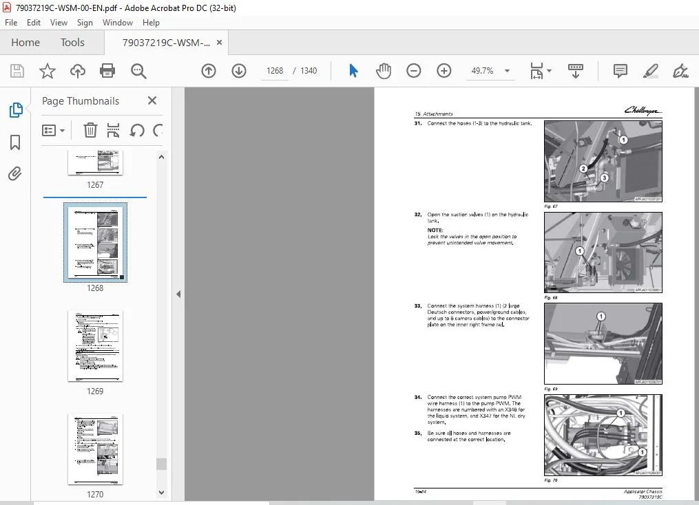
15 Attachments 1 5- 1
15 1 Tool box 1 5-3
15 1 1 R emove the tool box 15-3
15 1 2 Install the tool box 15-4
15 2 Crop defl ector 1 5-5
Applicator Chassis
79037219C
Table of contents
1 5 2 1 Remove the crop deflector 1 5-5
1 5 2 2 Install the crop deflector 1 5-6
15 3 Boom rest 15-7
1 5 3 1 Remove the boom-rest 1 5-7
1 5 3 2 Install the boom-rest 1 5-8
15 4 Changing the system 15-10
1 5 4 1 Remove the liquid system 1 5-10
1 5 4 2 Install the spinner system 1 5-1 9
1 5 4 3 Install the Air Max 1 80 system 1 5-2 5
1 5 4 4 Remove the Air Max 1 80 system 1 5-2 8
1 5 4 5 Remove the s pinner system 1 5-3 1
1 5 4 6 Install the liquid system 1 5-3 6
16 Accessories 16-1
16 1 Hand rinse tank 16-3
1 6 1 1 Remove the hand rinse tank 1 6-3
1 6 1 2 Install the hand rinse tank 1 6-4
17 Diagrams 17-1
17 1 Chassis hydraulic schematics 17-3
1 7 1 1 Chassis hydraulic schematic 1 7-5
1 7 1 2 Track adjust cylinder extend 1 7-9
1 7 1 3 Track adjust cylinder retract 1 7-10
1 7 1 4 Track adjust solenoid chart 17-1 1
1 7 1 5 Service brake 1 7-1 2
1 7 1 6 Pressure washer circuit if equipped 1 7-1 3
17 2 Air system schematics 17-14
1 7 2 1 Air system schematic with the air dryer 1 7-1 4
1 7 2 2 Air system schematic without the air dryer 1 7-1 6
17 3 Component location charts 17-18
1 7 3 1 Battery box connector location diagram 1 7-1 9
1 7 3 2 Front chassis electrical connector location diagram 1 7-20
1 7 3 3 Middle chassis electrical connector location diagram 1 7-2 1
1 7 3 4 Rear chassis electrical connector location diagram 1 7-2 2
1 7 3 5 Cab top electrical connector location diagram 1 7-2 3
1 7 3 6 Cab bulkhead connector location diagram 1 7-2 4
1 7 3 7 Cab electrical panel connector location diagram 1 7-2 5
1 7 3 8 Cab middle harness connector location diagram 1 7-2 6
18 Index l n d ex-1
FILE DETAILS:
Challenger EU Applicators RG900C RG1100C RG1300C RoGator Chassis Workshop Service Manual – PDF DOWNLOAD
Size: 187 MB
Format: PDF
Language: English
Brand: Challenger
Type of Machine: Applicators
Type of document: Workshop Service Manual
Model: Challenger EU RoGator RG900C RG1100C RG1300C Applicator Chassis
Number of Pages: 1340 pages
Part Number: 79037219C
Date Modified: 08/2019
CHALLENGER EU APPLICATORS RG900C RG1100C RG1300C ROGATOR CHASSIS WORKSHOP SERVICE MANUAL:
IMAGES PREVIEW OF THE MANUAL:


PLEASE NOTE:
- This is the SAME manual used by the dealers to troubleshoot any faults in your vehicle. This can be yours in 2 minutes after the payment is made.
- Contact us at [email protected] should you have any queries before your purchase or that you need any other service / repair / parts operators manual.
S.V