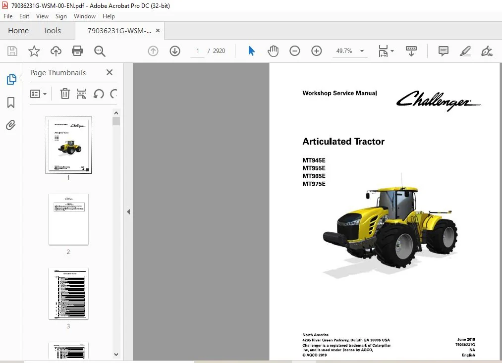
Challenger EU Articulated Tractor MT945E MT955E MT965E MT975E Workshop Service Manual
Original price was: $89.95.$26.95Current price is: $26.95.
Challenger EU Articulated Tractor MT945E MT955E MT965E MT975E Workshop Service Manual – PDF DOWNLOAD
Description
Challenger EU Articulated Tractor MT945E MT955E MT965E MT975E Workshop Service Manual – PDF DOWNLOAD
IMAGES PREVIEW OF THE MANUAL:


DESCRIPTION:
Challenger EU Articulated Tractor MT945E MT955E MT965E MT975E Workshop Service Manual – PDF DOWNLOAD
А word to the technician:
Read and understand the safety section in this service manual before operating or servicing the machine. Read and understand the safety sections in the manuals for all attachments before operating or servicing attachments. The technician has the key to safety. Good safety practices protect everyone. S tudy the safety information in this service manual . Make the safety information а working part of the safety program.
- The safety information in this servic e manual applies spec ifically to this type of machine. Always do all other usual and customary safe working precautions. Remember – The technician has the responsibility for safety.
- Good safety practices сап prevent serious inj ury or death. The safety section points out some basic safety situations that сап occur during the operation and maintenance of the machine. The safety section also suggests possiЫe ways to deal with these situations.
- The safety section does not replace safety practices in other parts of this service manual . Prac tic e good safety to help prevent injury or death. Learn how to operate the machine and how to use the controls correctly.
- Do not let other persons operate the machine without instruction and training. Follow all safety precautions and instructions i n the manuals and оп safety signs affixed to the machine and all attachments. U se only approved attachments and eq uipment. Make sure the machine has the correct eq uipment needed Ьу the local regulations.
FILE DETAILS:
Challenger EU Articulated Tractor MT945E MT955E MT965E MT975E Workshop Service Manual – PDF DOWNLOAD
Size : 393 MB
Format : PDF
Language : English
Brand: Challenger EU
Type of machine: Agricultural-Tractor
Type of document: Workshop Service Manual
Model: Challenger EU MT945E MT955E MT965E MT975E Articulated Tractor
Date: 2019
Number of Pages: 2920 Pages
Part Number: 79036231G
TABLE OF CONTENTS:
Challenger EU Articulated Tractor MT945E MT955E MT965E MT975E Workshop Service Manual – PDF DOWNLOAD
1 General 1-1
1 1 Safety information 1-3
1 1 1 А word to the technician 1-3
1 1 2 Service manual 1-4
1 1 3 Safety symbol 1-4
1 1 4 Safety messages 1-4
1 1 5 lnformation messages 1-4
1 1 6 Safety signs 1-5
1 1 7 lmportant safety information 1-5
1 1 8 General hazard information 1-6
1 1 9 Pressurized air 1-7
1 1 10 Asbestos information 1-7
1 1 1 1 Electrical storm injury prevention 1-7
1 1 1 2 Mount and dismount the machine 1-7
1 1 1 3 Before you start the engine 1-8
1 1 1 4 Start the engine 1-8
1 1 1 5 Before operation 1-8
1 1 1 6 Procedures for operation 1-8
1 1 1 7 Park the machine 1-9
1 1 1 8 Operator station 1-9
1 1 1 9 Cut and crush prevention 1-10
1 1 20 Rollover protective structure 1-10
1 1 21 Burn prevention 1-10
1 1 22 Coolant 1-1 1
1 1 23 Oils 1-1 1
1 1 24 High pressure lines 1-1 1
1 1 25 Fluid penetration 1-1 2
1 1 26 Batteries 1-1 2
1 1 27 Exhaust fumes 1-1 3
1 1 28 Noise prevention 1-1 4
1 1 29 Fire and explosion prevention 1-1 4
1 1 30 Fire extinguisher 1-1 5
1 1 31 PuЫic road transportation 1-1 5
1 2 Serial number definition 1-16
1 3 Proper disposal of waste 1-17
1 4 Lubricant viscosities and refill capacities 1-18
1 4 1 Lubricant viscosities for ambient temperatures 1-1 8
1 4 2 Lubricant viscosities 1-1 8
1 4 3 Fill capacities 1-1 8
1 5 Service intervals 1-19
1 5 1 Maintenance chart 1-1 9
1 5 2 Maintenance schedule 1-20
1 6 Engine specifications – МТ900Е 1-22
1 7 Torque specifications 1-24
1 7 1 Constant torque hose clamps 1-24
1 7 2 lnch fasteners 1-24
1 7 3 Metric fasteners 1-27
1 8 Machine specifications 1-29
1 8 1 Machine specifications МТ900Е 1-29
1 8 2 Shipping weights МТ900Е 1-31
Articulated Tractor
79036231G
ТаЬ!е of contents
2 Engine, fuel, and exhaust system 2-1
2 1 Engine maintenance 2-7
2 1 1 Replace the engine air filter 2-7
2 1 2 Change the prefilter and the fuel filters 2-7
2 2 Engine system components 2-9
2 2 1 Remave the main serpentine belt 2-9
2 2 2 lnstall the main serpentine belt 2-10
2 2 3 Remave the accessaries belt 2-11
2 2 4 lnstalling the accessaries belt 2-13
2 2 5 Remave the alternatars 2-14
2 2 6 lnstall the alternatars 2-17
2 2 7 Remave the caaling package 2-19
2 2 8 lnstall the caaling package 2-2 7
2 2 9 Remave the radiatar саге 2-34
2 2 10 lnstall the radiatar саге 2-43
2 2 11 Remave the implement ail caaler 2-5 0
2 2 12 lnstall the implement ail caaler 2-5 9
2 2 13 Remave the transmissian caaler 2-66
2 2 14 lnstall the transmissian caaler 2-75
2 2 15 Remave the air canditianing candenser 2-82
2 2 16 lnstall the air canditianing candenser 2-85
2 2 17 Remave the fuel caaler 2-86
2 2 18 lnstall the fuel caaler 2-88
2 2 19 Remave the charge air caaler 2-89
2 2 2 0 lnstall the charge air caaler 2-97
2 2 2 1 Remave the air canditianing receiver/dryer 2-105
2 2 2 2 lnstall the air canditianing receiver/dryer 2-107
2 2 2 3 Remave the engine maunts 2-109
2 2 2 4 lnstall the engine maunts 2-110
2 2 2 5 Remave the air filter assemЫy 2-111
2 2 2 6 lnstall the air filter assemЬly 2-114
2 2 2 7 Remave the fan 2-117
2 2 2 8 lnstall the fan 2-12 0
2 2 2 9 Remave the air campressar 2-12 2
2 2 30 lnstall the air campressar 2-12 5
2 2 31 Remave а starter 2-12 7
2 2 32 lnstall а starter 2-12 9
2 2 33 Remave the engine 2-131
2 2 34 lnstalling the engine 2-140
2 3 Flush and refill the cooling system 2-148
2 3 1 Caalant system fluid 2-148
2 3 2 Flush the caaling system 2-148
2 3 3 Refill the caaling system 2-149
2 4 Engine trouЬleshooting 2-150
2 4 1 Engine derating 2-15 4
2 5 Fuel system components 2-158
2 5 1 Remave the fuel lines 2-15 8
2 5 2 lnstall the fuel lines 2-161
2 5 3 Remave the primary fuel filter 2-163
2 5 4 lnstall the primary fuel filter 2-165
2 5 5 Remave the secandary fuel filter 2-166
2 5 6 lnstall the secandary fuel filter 2-168
2 5 7 Remave the fuel / water separatar 2-168
2 5 8 lnstall the fuel / water separatar 2-170
2 5 9 Prime the fuel system 2-172
2 5 10 Remave the diesel exhaust fluid system 2-173
2 5 11 lnstall the diesel exhaust fluid system 2- 17 5
Exhaust system components 2-178
2 6 1 Remove the exhaust system with the diesel exhaust fluid system 2- 178
2 6 2 lnstall the exhaust system with the diesel exhaust fluid system 2- 18 4
2 6 3 Remove the exhaust system 2- 19 0
2 6 4 lnstall the exhaust system 2- 19 3
SCR system 2-196
2 7 1 Selective catalytic reduction (SCR) System 2- 19 6
2 7 2 Su p ply module 2- 19 6
2 7 3 Fill the diesel exhaust fluid tank 2- 197
2 7 4 DEF heater circuit fuse 2- 197
2 7 5 DEF storage and shelf life 2- 197
2 7 6 Low diesel exhaust fluid (DEF) level 2- 198
Fluid specifications 2-20 0
2 8 1 Oil s pecification 2-2 0 0
2 8 2 Fuel s pecifications 2-2 0 0
2 8 3 Coolant s pecification 2-2 0 0
Safety instructions 2-201
То the user 2-203
2 10 1 Engine ty pe designations 2-2 0 3
2 10 2 Location of the engine serial number 2-2 0 4
2 10 3 Marking of the electronic control unit 2-2 0 5
2 10 4 Lifting the engine 2-2 0 6
Engine construction 2-208
2 11 1 Engine overview 2-2 08
2 11 2 Technical data 2-2 10
2 11 2 1 Princi pal dimensions and data 2-2 10
2 11 2 2 Fuel system 2-2 10
2 11 2 3 Lubrication system 2-2 10
2 11 2 4 Cooling system 2-2 11
2 11 2 5 Electrical system 2-2 11
2 11 2 6 SCR system technical data 2-2 11
Cylinder Ыосk 2-2 11
Flywheel housing 2-2 12
Valve mechanism 2-2 12
Cylinder head 2-2 12
Crank mechanism 2-2 12
Timing gears 2-2 13
Lubrication system 2-2 14
2 11 9 1 Oil pum p 2-2 1 5
2 11 9 2 Oil filter and oil cooler 2-2 1 5
2 11 10 Cooling system 2-2 16
2 11 10 1 Coolant pum p 2-2 18
2 11 10 2 Thermostats 2-2 18
2 11 11 Air control system 2-2 2 0
2 11 11 1 2 stage turbocharging 2-2 2 1
2 11 11 2 lnterstage charge air cooling 2-2 2 1
2 11 11 3 Throttle valve 2-2 2 1
2 11 11 4 Exhaust gas recirculation system 2-2 2 2
2 11 12 Fuel system 2-2 2 2
2 11 13 SCR system overview 2-2 2 4
2 11 13 1 SCR system com ponents and their functions 2-2 2 5
2 11 14 Engine control system 2-2 2 6
2 11 14 1 Engine wiring 2-2 2 7
Technical data 2-228
2 12 1 Cylinder Ыосk 2-2 28
2 12 2 Cylinders of the 12 cylinder engine 2-2 29
Articulated Tractor
79036231G
ТаЬ!е of contents
2 13
2 14
2 15
2 16
2 17
2 18
2 19
2 12 3
2 12 4
2 12 5
2 12 6
2 12 7
2 12 8
2 12 9
2 12 10
2 12 11
2 12 12
2 12 13
Cylinder liners 2-2 29
Cylinder head 2-2 30
Valves and rockers 2-2 30
Ta p pets and push rods 2-2 3 1
Camshaft 2-2 32
Crankshaft 2-2 32
Flywheel 2-2 33
Timing gears 2-2 33
Connecting rod 2-2 34
Piston, rings and pin 2-2 34
Lubrication system 2-2 35
2 12 13 1 Oil pum p 2-2 36
2 12 14 Thermostat 2-2 36
2 12 15 Turbocharger 2-2 36
Liquid quality requirements 2-23 7
2 13 1 Oil quality requirements 2-2 37
2 13 2 Coolant quality requirements 2-2 37
2 13 3 Fuel quality requirements 2-2 37
2 13 3 1 Biodiesel Ыends 2-2 39
2 13 3 2 Engine out put de pending оп fuel quality 2-2 4 0
Tightening torques 2-2 41
Special tools 2-2 43
2 15 1 Engine lifting tools 2-2 4 3
2 15 2 Cylinder Ыосk tools 2-2 4 3
2 15 3 Timing gear and flywheel housing tools 2-2 46
2 15 4 Cylinder head and valve mechanism tools 2-2 47
2 15 5 Crank mechanism tools 2-2 49
2 15 6 Lubrication system tools 2-2 49
2 15 7 Coolant pum p tools 2-2 49
2 15 8 Fuel system tools 2-2 5 0
2 15 9 SCR system tools 2-2 5 4
2 15 10 Electronic diagnostic tool 2-255
2 15 10 1 EDT diagnostic terminal 2-2 5 6
2 15 10 2 Diagnostic terminal com ponents 2-2 5 6
Major maintenance and engine replacement 2-258
2 16 1 Pre pare а major engine maintenance 2-258
2 16 2 Pre pare the long Ыосk re placement 2-258
2 16 3 How to su p port the engine in а major maintenance 2-259
2 16 4 Remove the parts оп to p of the long Ыосk engine 2-2 62
2 16 5 lnstall the parts оп to p of the long Ыосk engine 2-2 69
2 16 6 Starting the engine after major maintenance 2-2 7 6
2 16 7 U pdate the engine software 2-2 77
2 16 8 Break in the engine 2-2 77
Cylinder Ыосk 2-278
2 17 1 Measure the cylinder liner wear 2-2 78
2 17 2 Remove the cylinder liner 2-2 78
2 17 3 Do а check for the cylinder Ыосk 2-2 78
2 17 4 Re place the camshaft bushing 2-2 79
2 17 5 Fitting plug at camshaft rear end 2-28 0
2 17 6 lnstall the cylinder liner 2-28 0
Flywheel housing 2-28 4
2 18 1 Remove the flywheel housing 2-28 4
2 18 2 lnstall the flywheel housing 2-28 4
2 18 3 Changing crankshaft rear oil seal 2-28 4
Cylinder head 2-28 6
2 19 1 Remove the cylinder heads 2-28 6
2 19 2 Removing valves 2-28 6
Articulated Тractor
79036231G
ТаЬ!е of contents
2 19 3 Do а check for the cylinder head 2-286
2 19 4 Replace the valve guides 2-288
2 19 5 Machine the valve seat 2-288
2 19 6 Replace the valve seat rings 2-288
2 19 7 Grinding valves 2-289
2 19 8 Fitting valves 2-29 0
2 19 9 lnstall the cylinder head 2-29 0
2 20 Valve mechanism 2-292
2 2 0 1 Reconditioning the valve mechanism 2-29 2
2 2 0 2 Compressing the oil out from the hydraulic lash adjusters 2-29 2
2 2 0 3 AssemЫing the valve mechanism with the hydraulic lash adjusters 2-29 3
2 2 0 4 Pre-adjusting the hydraulic lash adjusters 2-29 4
2 2 0 5 Replace the camshaft ог the camshaft gear 2-296
2 21 Crankshaft 2-298
2 2 1 1 Remove the crankshaft 2-298
2 2 1 2 Do а check for the crankshaft 2-299
2 2 1 2 1 Rework instructions for the crankshaft 2-30 0
2 2 1 3 Replace the crankshaft gears 2-30 1
2 2 1 4 lnstall the crankshaft 2-30 2
2 2 1 5 Viscose type vibration damper 2-305
2 22 Connecting rods and pistons 2-306
2 2 2 1 Removing pistons together with connecting rods 2-306
2 2 2 2 Replace the piston rings 2-306
2 2 2 3 Replace the connecting rod bearings 2-30 7
2 2 2 3 1 Piston pin bushing 2-30 7
2 2 2 3 2 Big-end bearing 2-308
2 2 2 4 Do а check for the connecting rod 2-308
2 2 2 5 Checking pistons 2-31 0
2 2 2 6 lnstall the piston pin 2-31 1
2 2 2 7 lnstall the piston together with the connecting rod 2-31 1
2 23 Flywheel 2-313
2 2 3 1 Changing starter ring gear оп flywheel 2-31 3
2 2 3 2 Remove the flywheel 2-31 3
2 2 3 3 Fitting flywheel 2-31 3
2 24 Timing gear assemЫy 2-314
2 2 4 1 Remove the timing gear housing 2-31 4
2 2 4 2 lnstall the timing gear housing 2-315
2 2 4 3 Crankshaft hub piece 2-319
2 2 4 4 Fitting the crankshaft hub 2-319
2 25 Belts 2-320
2 25 1 Remove the belt tensioner 2-32 0
2 25 2 lnstall the belt tensioner 2-32 0
2 25 3 Remove the belt pulley 2-32 1
2 25 4 lnstall the belt pulley 2-32 1
2 26 Lubrication system 2-322
2 26 1 Do а check for the oil pressure regulating valve 2-32 2
2 26 2 Removing the oil pump 2-32 2
2 26 3 Fitting the oil pump 2-32 2
2 26 4 Piston cooling nozzles 2-32 3
2 26 5 Fitting the oil sump gasket 2-325
2 26 6 Removing the oil cooler 2-325
2 26 7 Fitting the oil cooler 2-325
2 26 8 Oil sump capacity 2-326
2 26 9 Closed crankcase ventilation 2-326
2 26 9 1 lnstalling the closed crankcase ventilation system components 2-326
2 26 1 0 Change oil filter 2-32 7
2 27 Cooling system 2-328
Articulated Tractor
79036231G
ТаЬ!е of contents
2 2 7 1 Remove the thermostats 2-328
2 2 7 2 Testing the thermostat 2-328
2 2 7 3 Re place the thermostat 2-329
2 2 7 4 Reconditioning the coolant pum p 2-329
2 2 7 5 lnstalling the cylinder head connection part 2-332
2 2 7 6 Remove the rear distribution unit of the coolant 2-332
2 2 7 7 lnstall the rear distribution unit of the coolant 2-333
2 28 Air control system maintenance 2-334
2 28 1 Checking the air cleaner 2-334
2 28 2 Checking the inlet and exhaust pi pes 2-334
2 28 3 Remove the exhaust manifold 2-335
2 28 4 lnstall the exhaust manifold 2-335
2 28 5 Remove the inlet manifold 2-336
2 28 6 lnstall the inlet manifold 2-336
2 28 7 Remove the actuator of the turbocharger 2-337
2 28 8 lnstall the actuator of the turbocharger 2-337
2 28 9 Remove the low-pressure turbochargers with the mounting bracket 2-338
2 28 10 lnstall the low-pressure turbochargers with the mounting bracket 2-339
2 28 1 1 Removing the turbocharger 2-340
2 28 12 Checking the turbocharger 2-340
2 28 13 lnstall the high-pressure turbocharger 2-34 1
2 28 14 Remove the EGR actuator 2-342
2 28 1 5 lnstall the EGR actuator 2-34 3
2 28 16 EGR link rod 2-34 3
2 28 17 Checking the EGR actuator voltages 2-34 3
2 28 18 Removing the ICACs with the mounting bracket 2-344
2 28 19 Fitting the ICACs with the mounting bracket 2-34 5
2 28 2 0 Remove the EGR coolers with the air pi pes and the high-pressure turbochargers 2-34 5
2 28 2 1 lnstall the EGR coolers with the air pi pes and the high-pressure turbochargers 2-347
2 29 Fuel system 2-349
2 29 1 Bleed the fuel system 2-349
2 29 2 Measuring fuel feed pressure 2-349
2 29 3 Remove the fuel filters with the fuel filter bracket 2-350
2 29 4 lnstall the fuel filters with the fuel filter bracket 2-35 1
2 29 5 Remove the injector overflow pi pe 2-352
2 29 6 lnstall the injector overflow pi pe 2-353
2 29 7 lns pecting injectors 2-353
2 29 7 1 Remove the injectors (CRIN3) 2-353
2 29 7 2 lnstall the injectors (CRIN3) 2-355
2 29 8 High-pressure pum p 2-357
2 29 8 1 Removing the high-pressure pum p 2-357
2 29 8 2 lnstall the high-pressure pum p 2-358
2 29 9 Rail 2-359
2 29 9 1 Removing the rail 2-36 0
2 29 9 2 Fitting the rail 2-36 1
2 29 9 3 Removing the pressure control valve 2-36 1
2 29 9 4 Fitting the pressure control valve 2-36 1
2 29 9 5 Removing the pressure sensor 2-362
2 29 9 6 Fitting the pressure sensor 2-362
2 30 SCR system 2-363
2 30 1 SCR system maintenance 2-363
2 30 2 Mounting of SCR system com ponents 2-363
2 30 3 Removing the su p ply module 2-364
2 30 4 lnstalling the su p ply module 2-364
2 30 5 Removing the hydraulic connectors 2-36 5
2 30 6 lnstalling the hydraulic connectors 2-36 5
2 30 7 Re place the main filter and the inlet filter of the su p ply module 2-36 5
2 30 8 S PN 52 10 08 F MI 1 2-366
Articulated Тractor
79036231G
ТаЬ!е of contents
2 30 8 1 Solve the DEF pressure build-u p failure 2-367
2 30 8 2 Su p ply module lifting ca pacity test 2-369
2 30 8 3 Solve the failure when the S M lifting ca pacity test is not О К 2-37 0
2 30 8 4 Solving the failure when the S M lifting ca pacity test is О К 2-372
2 30 9 SPN 52 10 2 5F MI 31, SPN 52 10 2 6F MI 31 2-373
2 30 9 1 Cleanu p of the SCR catalyst 2-37 5
2 30 9 2 Make the dosing rate test 2-376
2 30 9 3 Checking the quality of DEF 2-38 0
2 31 Engine control system 2-3 8 2
2 3 1 1 Re place the electronic control unit 2-38 2
2 3 1 2 Re place an em pty electronic control unit (ECU) 2-38 3
2 3 1 3 Re place the engine wiring harness 2-38 3
2 3 1 3 1 Ргера ге the wiring harness re placement 2-38 3
2 3 1 3 2 Engine wiring harness, main 2-38 4
2 3 1 3 3 Engine wiring harness of the actuators 2-38 5
2 3 1 3 4 Remove the engine wiring harness of the actuators 2-38 5
2 3 1 3 5 Remove the engine wiring harness, main 2-38 5
2 3 1 3 6 lnstall the engine wiring harness, main 2-389
2 3 1 3 7 lnstall the engine wiring harness of the actuators 2-39 2
2 3 1 3 8 Finalize the wiring harness re placement 2-39 3
2 32 Terminal diagram 2-3 94
3 Axles 3 -1
3 1 Axle system operation 3 -3
3 1 1 Axle introduction 3-3
3 1 2 Differential lock 3-3
3 1 3 Axle lubrication 3-3
3 1 4 Service brakes 3-3
3 1 5 Park brake 3-3
3 1 6 Final drives 3-3
3 1 7 Differential 3-4
3 2 Differential lock system 3 -6
3 2 1 Electrical com ponents of the differential lock system 3-7
3 2 2 Differential lock switch 3-8
3 2 3 Brake pedal switch 3-8
3 2 4 One-Touch switch 3-8
3 2 5 Differential lock solenoid 3-9
3 2 6 Hydraulic com ponents of the differential lock system 3- 10
3 2 7 Transmission sum p 3-11
3 2 8 Suction screen (charge pum p) 3- 11
3 2 9 Tri-section pum p 3- 12
3 2 10 Transmission oil filter 3- 12
3 2 1 1 Transmission oil filter by pass valve 3- 12
3 2 12 Oil sam pling valve 3- 13
3 3 Axle lubrication 3 -1 4
3 3 1 Axle lubrication system 3- 14
3 3 2 Tri-section pum p 3- 16
3 3 3 Axle lubrication filter 3- 17
3 4 Axle components 3 -18
3 4 1 Remove the front axle 3- 18
3 4 2 lnstall the front axle 3-2 2
3 4 3 Remove the геа г axle 3-2 5
3 4 4 lnstall the геа г axle 3-30
3 4 5 Remove the tri-section pum p 3-33
3 4 6 DisassemЫe the tri-section front pum p 3-35
3 4 7 DisassemЫe the tri-section геа г pum p 3-42
3 4 8 AssemЫe the tri-section front pum p 3-47
Articulated Tractor
79036231G
ТаЬ!е of contents
3 4 9 AssemЫe the tr-i section геа г pump 3-5 3
3 4 1 0 Ргера ге the pump fo r service 3-59
3 4 1 1 l nstall the tr-i section pump 3-6 0
3 4 1 2 Remo ve the differential lo ck so leno id valve 3-6 1
3 4 1 3 DisassemЫe the differential lo ck so leno id valve 3-6 2
3 4 1 4 AssemЫe the differential lo ck so leno id valve 3-6 3
3 4 15 lnstall the differential lo ck so leno id valve 3-6 4
3 4 16 Remo ve the axle lubricatio n filter ho usi ng 3-6 4
3 4 1 7 lnstall the axle lubricatio n filter ho using 3-68
3 4 18 Remo ve the lubricatio n filter pressure switch 3-7 1
3 4 19 l nstall the lubri catio n filter pressure switch 3-7 2
3 4 2 0 Remo ve the cassette seal 3-7 2
3 4 2 1 l nstall the cassette seal 3-7 3
3 4 2 2 Remo ve the final drive 3-74
3 4 2 3 l nstall the final drive 3-76
3 5 Final drive disassemЫy 3-79
3 5 1 DisassemЫe the final drive 3-79
3 5 2 DisassemЫe the primary planetary carrier 3-8 7
3 5 3 DisassemЫe the seco ndary planetary carrier 3-88
3 5 4 DisassemЫe the axle shaft bearings 3-89
3 6 Final drive assemЫy 3-91
3 6 1 AssemЫe the axle shaft bearings 3-9 1
3 6 2 S him the axle shaft bearings 3-9 4
3 6 3 AssemЫe the seco ndary planetary carrier 3-98
3 6 4 AssemЫe the primary planetary carrier 3-1 0 0
3 6 5 AssemЫe the final drive 3-1 0 0
3 7 Differential disassemЫy 3-108
3 7 1 Ex plo ded view o f the differential 3-1 08
3 7 2 Remo ve the drive pinio n 3-1 08
3 7 3 DisassemЫe the drive pinio n 3-1 1 0
3 7 4 DisassemЫe the park brake 3-1 1 1
3 7 5 Remo ve the left-hand carrier 3-1 15
3 7 6 DisassemЫe the right-hand carrier 3-1 1 7
3 7 7 DisassemЫe the left-hand carrier 3-1 19
3 7 8 Remo ve the differential unit 3-1 2 0
3 7 9 DisassemЫe the differential half-ho using 3-1 2 1
3 7 1 0 DisassemЫe the needle bearing half-ho using 3-1 2 4
3 8 Differential assemЫy 3-130
3 8 1 Ex plo ded view o f the differential 3-1 30
3 8 2 AssemЫe the differential half-ho using 3-1 30
3 8 3 AssemЫe the needle bearing half-ho using 3-1 34
3 8 4 l nstall the differential unit 3-1 4 1
3 8 5 AssemЫe the left-hand carrier 3-1 4 1
3 8 6 AssemЫe the right-hand carri er 3-1 4 3
3 8 7 S et the bevel gear positio n 3-1 45
3 8 8 S et the differential bearing prelo ad 3-1 45
3 8 9 l nstall the left-hand carrier 3-1 46
3 8 1 0 Do а test o f the service brake 3-1 48
3 8 1 1 AssemЫe the drive pinio n 3-1 49
3 8 1 2 S et the pinio n po sitio n 3-15 1
3 8 1 3 S et the pinio n bearing prelo ad 3-15 2
3 8 1 4 Do а check o f the backlash in the pinio n shaft 3-15 4
3 8 15 l nstall the drive pinio n 3-155
3 8 16 l nstall the differential studs 3-158
3 9 Axle maintenance 3-159
3 9 1 Replace the axle lubricatio n filter 3-159
3 9 2 Remo ve the cassette seal 3-159
Articulated Тractor
79036231G
ТаЬ!е of contents
3 9 3 lnstall the cassette seal 3- 159
3 10 Axle testing and adjusting 3- 1 62
3 10 1 Air test the axle 3- 162
3 10 2 Set the bevel gear position 3- 16 3
3 10 3 Set the differential bearing preload 3- 16 3
3 10 4 Do а test of the service brake 3- 164
3 10 5 Set the pinion position 3- 166
3 10 6 Set the pinion bearing preload 3- 167
3 11 Axle comnponent specifications 3- 1 7 0
3 11 1 Tri-section pum p 3- 17 0
3 11 2 Axle lubrication filter 3- 17 1
3 11 3 Axle lubrication pressure switch 3- 17 1
4 Frame and suspension 4- 1
4 1 Split the machine 4-3
4 1 1 Disconnect the u p per articulation front joint 4-9
4 1 2 Disconnect the lower articulation joint 4- 12
4 1 3 Remove the u p per articulation to p link 4- 13
4 1 4 DisassemЫe the to p link 4- 14
4 2 Connect the machine 4- 1 6
4 2 1 AssemЫe the to p link 4- 16
4 2 2 AssemЫe the to p link -scra per o ption 4- 17
4 2 3 lnstall the u p per articulation to p link 4- 18
4 2 4 Connect the lower articulation joint 4- 19
4 2 5 Connect the u p per articulation front joint 4-2 0
4 3 Replace the articulation bearing 4-25
4 4 Frame repair 4-33
4 5 Repair the frame Ьу adding weld material and machining 4-34
4 6 Articulation position sensor 4-35
4 6 1 Remove the articulation position sensor 4-35
4 6 2 lnstall the articulation position sensor 4-38
4 6 3 Calibrate the articulation position sensor 4-4 1
4 7 Specifications 4-42
4 7 1 Articulation position sensor 4-42
5 Steering system 5- 1
5 1 Steering system layout 5-3
5 2 Steering system components 5-5
5 2 1 lm plement hydraulic pum p 5-5
5 2 2 Steering – priority valve 5-6
5 2 3 Steering unit 5-6
5 2 4 Hydraulic oil reservoir 5-7
5 2 5 Breather 5-8
5 2 6 Magnets 5-8
5 2 7 Oil drain plugs 5-8
5 2 8 Oil level switch 5-9
5 2 9 Oil tem perature sensor 5-9
5 2 10 Sight gauge 5-9
5 2 1 1 Suction screen (charge pum p) 5- 10
5 2 12 Suction screen (im plement pum p) 5-10
5 2 13 Load sense Ыocking valve 5- 11
5 2 14 Steering cylinder test ports 5- 11
5 2 15 Articulation position sensor 5- 11
5 2 16 Steering angle sensor 5- 12
5 2 17 Tractor management center 5- 12
5 2 18 Transmission module 5- 12
Articulated Tractor
79036231G
ТаЬ!е of contents
5 2 19 Armrest module 5-1 3
5 2 2 0 Dash cluster 5-1 3
5 2 2 1 CAN data link 5-1 3
5 2 2 2 l mplement filter bypass switch 5-1 4
5 3 Steeri n g system o peration 5 -15
5 3 1 S tandard steering system – left-hand turn 5-15
5 3 2 S tandard steering system – right-hand turn 5-1 7
5 3 3 E lectronic steering system – left-hand turn 5-19
5 3 4 E lectronic steering system – right-hand turn 5-2 1
5 3 5 S tandard steering – priority valve – right turn 5-2 3
5 3 6 S tandard steering – priority valve – left turn 5-25
5 3 7 E lectronic steering – priority valve – right turn 5-2 7
5 3 8 E lectronic steering – priority valve – left turn 5-29
5 3 9 S teering – priority valve – neutral 5-31
5 3 1 0 S teering unit neutral position 5-32
5 3 1 1 S teering unit right-hand turn position 5-33
5 3 1 2 S teering unit left-hand turn position 5-34
5 3 1 3 H ydraulic pump ( implement) 5-34
5 3 1 4 Compensator valve 5-35
5 3 15 Low pressure standby 5-36
5 3 16 U pstroke 5-36
5 3 1 7 Constant flow 5-36
5 3 18 Destroke 5-37
5 3 19 H igh pressure stall 5-37
5 3 2 0 H igh pressure cutoff 5-37
5 4 Steeri n g system d isassem Ыy a n d assemЫy 5 -39
5 4 1 Remove the gear pump 5-39
5 4 2 DisassemЫing the gear pump 5-4 2
5 4 3 AssemЬ le the gear pump 5-45
5 4 4 lnstall the gear pump 5-48
5 4 5 Remove the steeri ng and implement pump 5-5 1
5 4 6 lnstall the steer ing – implement pump 5-55
5 4 7 Remove the steeri ng and priority valve 5-58
5 4 8 lnstall the steer ing and priority valve 5-6 2
5 4 9 Remove the steeri ng unit 5-65
5 4 1 0 lnstall the steer ing unit 5-6 7
5 4 1 1 Remove the steering cylinders 5-69
5 4 1 2 lnstall the steering cylinder 5-7 3
5 4 1 3 Remove the hydraulic oil reservoir 5-76
5 4 1 4 DisassemЫe the hydraulic oil reservoir 5-79
5 4 15 AssemЫe the hydraulic oil reservoir 5-8 3
5 4 16 lnstall the hydraulic oil reservoir 5-86
5 4 1 7 Remove the hydraulic oil filter manifold ( steering – i mplement) 5-88
5 4 18 l nstall the hydraulic oil filter manifold ( steering – implement) 5-9 2
5 4 19 Remove the load sense Ыocking valve 5-9 4
5 4 2 0 l nstalling the load sense Ыocking valve 5-9 7
5 5 Steeri n g system test a n d adj u st 5 -10 0
5 5 1 Adjust the load sense relief valve for the steering valve 5-1 0 0
5 5 2 Bleed the steering system 5-1 0 2
5 5 3 Do а check of the steering performance and pressure 5-1 0 2
5 5 4 Test the implement oil cooler bypass valve pressure 5-1 0 3
5 6 Steeri n g system m a i ntenance 5 -105
5 6 1 Remove the suction screen ( charge pump) 5-1 05
5 6 2 l nstall the suction screen ( charge pump) 5-1 0 7
5 6 3 Remove the suction screen ( implement pump) 5-1 1 0
5 6 4 l nstall the suction screen ( implement pump) 5-1 1 3
5 6 5 Replace the hydraulic oil filters 5-1 15
Articulated Тractor
79036231G
ТаЬ!е of contents
5 6 6 Re place the hydraulic oil reservoir breather 5- 117
6 Drivetrain system 6-1
6 1 Transmission system 6-З
6 1 1 Transmission introduction 6-3
6 1 2 Transmission system 6-3
6 1 3 Transmission hydraulic system 6-4
6 1 4 Transmission electrical control system 6-6
6 1 5 Electronic controls 6-7
6 1 6 Tri-section pum p 6-8
6 1 7 Transmission charge filter 6-8
6 1 8 Charge pressure relief valve 6-8
6 1 9 Transmission modulating valves 6-8
6 2 Transmission 6-9
6 2 1 Remove the transmission 6-9
6 2 2 lnstall the transmission 6- 14
6 3 Drivetrain components 6-20
6 3 1 Remove the tri-section pum p 6-2 0
6 3 2 lnstall the tri-section pum p 6-2 2
6 3 3 Remove а transmission clutch modulating valve 6-2 3
6 3 4 DisassemЫe а transmission clutch modulating valve 6-2 4
6 3 5 AssemЫe а transmission clutch modulating valve 6-2 5
6 3 6 lnstall а transmission clutch modulating valve 6-2 5
6 3 7 Remove the transmission lubrication relief valve 6-2 6
6 3 8 lnstalling the transmission lubrication relief valve 6-2 6
6 3 9 Remove the charge pressure relief valve 6-2 7
6 3 10 lnstall the charge pressure relief valve 6-28
6 3 1 1 Remove the charge pressure sensor 6-29
6 3 12 lnstalling the charge pressure sensor 6-30
6 3 13 Removing the transmission oil cooler by pass valve 6-30
6 3 14 lnstall the transmission oil cooler by pass valve 6-3 1
6 3 15 Removing the transmission oil tem perature sensor 6-32
6 3 16 lnstall the transmission oil tem perature sensor 6-33
6 3 17 Remove the in put s peed sensors 6-33
6 3 18 lnstall the in put s peed sensors 6-34
6 3 19 Remove the out put s peed sensors 6-35
6 3 2 0 lnstall the out put s peed sensors 6-36
6 3 2 1 Remove the front drive shaft 6-37
6 3 2 2 DisassemЫe the front drive shaft 6-38
6 3 2 3 AssemЫe the front drive shaft 6-38
6 3 2 4 lnstall the front drive shaft 6-39
6 3 2 5 Remove the in put drive shaft 6-4 0
6 3 2 6 DisassemЫe the in put drive shaft 6-4 1
6 3 2 7 AssemЫe the in put drive shaft 6-4 1
6 3 28 lnstall the in put drive shaft 6-42
6 3 29 Remove the rear articulation drive shaft 6-4 3
6 3 30 DisassemЫe the rear articulation drive shaft 6-4 5
6 3 3 1 AssemЫe the rear articulation drive shaft 6-4 5
6 3 32 lnstall the rear articulation drive shaft 6-4 5
6 3 33 Remove the rear drive shaft 6-47
6 3 34 DisassemЫe the rear drive shaft 6-48
6 3 35 AssemЫe the rear drive shaft 6-49
6 3 36 lnstall the rear drive shaft 6-5 1
6 4 Transmission trouЬleshooting 6-52
6 5 Drivetrain system test and adjust 6-54
6 5 1 Test the im plement oil cooler pressure 6-54
6 6 Drive train maintenance 6-55
Articulated Tracto
Do а check of the power train fluid level – daily 6-55
Change the power train system fluid 6-55
Clean the breather ( transmissio n) 6-59
7 Brake system 7- 1
7 1 Service and brake system operation 7-З
7 1 1 S ervice and parking brake system Ы ос k diagram 7-3
7 1 2 S ervice brake operation 7-4
7 1 3 Parking brake operation 7-4
7 2 Trailer brake system (optional) 7-5
7 2 1 l mplement hydraulic pump 7-5
7 2 2 S teering – priority valve 7-6
7 2 3 H ydraulic o il reservoir 7-7
7 2 4 Breather 7-7
7 2 5 Magnets 7-8
7 2 6 Oil drain plugs 7-8
7 2 7 Oil level switch 7-8
7 2 8 Oil temperature sensor 7-9
7 2 9 S ight gauge 7-9
7 2 1 0 S uction screen ( charge pump) 7-9
7 2 1 1 S uctio n screen ( implement pump) 7-1 0
7 2 1 2 Trailer brake valve 7-1 1
7 2 1 3 Trailer brake co upler 7-1 1
7 2 1 4 Trailer brake schematic 7-1 2
7 З Service and parking brake components 7- 1 4
7 3 1 Tr-i section pump 7-1 4
7 3 2 Brake charge filter 7-1 4
7 3 3 Brake accumulator charge valve 7-15
7 3 4 Accumulator 7-15
7 3 5 Accumulato r pressure switch 7-16
7 3 6 S ervice brake valve 7-16
7 3 7 S ervice brakes 7-18
7 3 8 Park brake valve 7-19
7 3 9 Park brake valve – engaged 7-2 0
7 3 1 0 Parking brake valve – released 7-2 1
7 3 1 1 Parking brake valve – released with а non-operating engine 7-2 2
7 3 1 2 So leno id valve 1 (SV1 ) 7-2 2
7 3 1 3 So lenoid valve 2 (SV2 ) 7-2 3
7 3 1 4 Check valve 1 (CV1 ) 7-2 3
7 3 15 Manual pull valve ( М Р 1 ) 7-2 3
7 3 16 Pilot operated check valve (РС 1 ) 7-2 4
7 3 1 7 Park brake 7-2 4
7 4 Electrical components of park brake system 7-2 5
7 5 Position of electronic components for the parking brake system 7-27
7 5 1 Gear selector 7-2 7
7 5 2 CAN data link 7-2 7
7 5 3 Transmission module 7-28
7 5 4 Armrest mo dule 7-28
7 5 5 So lenoid valve ( parking brake) 7-28
7 6 Brake system disassemЫy and assemЫy 7-2 9
7 6 1 Remo ve the brake charge filter 7-29
7 6 2 l nstall the brake charge filter 7-30
7 6 3 Remo ve the brake accumulator charge valve 7-31
7 6 4 lnstall the brake accumulator charge valve 7-32
7 6 5 Remo ve the brake accumulato r 7-34
7 6 6 lnstall the brake accumulator 7-35
7 6 7 Remo ve the brake accumulato r switch 7-37
Articulated Тractor
79036231G
ТаЬ!е of contents
7 6 8 lnstall the brake accumulator switch 7-38
7 6 9 Remove the service brake valve 7-38
7 6 10 lnstall the service brake valve 7-4 0
7 6 11 Remove the parking brake valve 7-4 1
7 6 12 lnstall the parking brake valve 7-4 3
7 6 13 Remove the parking brake wear indicator 7-44
7 6 14 lnstall the parking brake wear indicator 7-4 5
7 6 15 Remove the parking brake pressure switch 7-46
7 6 16 lnstall the parking brake pressure switch 7-46
7 6 17 Remove the steering and im plement pum p 7-47
7 6 18 lnstall the steering -im plement pum p 7-5 1
7 6 19 Remove the steering and priority valve 7-55
7 6 2 0 lnstall the steering and priority valve 7-58
7 6 2 1 Remove the hydraulic oil reservoir 7-6 1
7 6 2 2 DisassemЫe the hydraulic oil reservoir 7-64
7 6 2 3 AssemЫe the hydraulic oil reservoir 7-68
7 6 2 4 lnstall the hydraulic oil reservoir 7-7 1
7 6 2 5 Remove the trailer brake valve 7-7 3
7 6 2 6 lnstall the trailer brake valve 7-7 5
7 6 2 7 Remove the trailer brake cou pler 7-7 6
7 6 28 lnstall the trailer brake cou pler 7-78
7 7 Brake system testing and adjusting 7-81
7 7 1 Brake trouЫeshooting 7-8 1
7 7 2 Tri-section pum p trouЫeshooting 7-8 2
7 7 3 Accumulator trouЫeshooting 7-8 3
7 7 4 Purge the service brake 7-8 4
7 7 5 Bleed the brake system pressure 7-8 6
7 7 6 Bleed the trailer brakes 7-8 7
7 8 Brake system maintenance 7-89
7 8 1 Re place the brake charge filter element 7-89
7 9 Brake system specifications 7-90
7 9 1 Brake charge filter 7-9 0
7 9 2 Accumulator charge valve 7-9 1
7 9 3 Accumulator 7-9 2
7 9 4 Accumulator pressure switch 7-9 3
7 9 5 Service brake valve 7-9 4
7 9 6 Park brake valve 7-9 5
7 9 7 Solenoid valve 1 (SV 1) 7-9 6
7 9 8 Solenoid valve 2 (SV 2) 7-9 7
7 9 9 Check valve 1 (CV 1) 7-98
7 9 10 Manual pull valve (М Р 1) 7-99
7 9 11 Pilot o perated check valve (РС 1) 7- 10 0
8 Compressed air system 8-1
8 1 Air system operation 8-З
8 1 1 Air system com ponents 8-3
8 2 Air system components 8-4
8 2 1 Remove the air com pressor 8-4
8 2 2 lnstall the air com pressor 8-7
8 2 3 Remove the air dryer 8-9
8 2 4 lnstall the air dryer 8- 11
8 2 5 Remove the main air reservoir 8- 12
8 2 6 lnstall the main air reservoir 8- 13
8 2 7 Remove the air cou pler 8- 14
8 2 8 lnstall the air cou pler 8- 1 5
8 2 9 Remove the regeneration reservoir 8- 17
8 2 10 lnstall the regeneration reservoir 8- 19
Articulated Tractor
79036231G
ТаЬ!е of contents
8 2 11 Remove the charging valve 8-2 0
8 2 12 lnstall the charging valve 8-2 1
8 2 13 Remove the air pressure sensor 8-2 2
8 2 14 lnstall the air pressure sensor 8-2 3
8 3 Air system component specifications 8-25
8 3 1 Main air reservoir 8-2 5
8 3 2 Air regeneration reservoir 8-2 5
8 3 3 Air com pressor 8-2 5
8 3 4 Air dryer 8-2 6
8 4 TrouЫeshoot the air dryer 8-27
8 5 Air system maintenance 8-31
8 5 1 Re place the desiccant cartridge 8-3 1
8 5 2 Re place the air dryer purge valve 8-3 1
8 5 3 Re place the air dryer regeneration valve 8-32
8 5 4 Re place the turbo cut off valve in the air dryer 8-33
9 Hydraulic system 9-1
9 1 lmplement hydraulic system introduction 9-3
9 1 1 lm plement system 9-4
9 1 2 lm plement electronic control system 9-5
9 1 3 lm plement hydraulic system 9-7
9 1 4 lm plement system control settings 9-9
9 2 lmplement hydraulic system components 9-10
9 2 1 Hydraulic oil reservoir 9- 11
9 2 2 Breather 9- 11
9 2 3 Magnets 9- 12
9 2 4 Oil drain plugs 9- 12
9 2 5 Oil level switch 9- 12
9 2 6 Oil tem perature sensor 9- 13
9 2 7 Sight gauge 9- 13
9 2 8 Suction screen (charge pum p) 9- 13
9 2 9 Suction screen (im plement pum p) 9- 14
9 2 10 lm plement oil filter 9- 14
9 2 11 lm plement filter by pass switch 9- 15
9 2 12 lm plement hydraulic pum p 9- 1 5
9 2 13 Hydraulic control valves 9- 16
9 2 14 Suction screen 9-2 1
9 2 15 Load sense Ыocking valve 9-2 1
9 2 16 Charge pum p 9-2 1
9 2 17 Steering – priority valve 9-2 2
9 2 18 Load sensing relief valve 9-2 3
9 2 19 lm plement oil cooler 9-2 3
9 2 2 0 Oil cooler by pass valve 9-2 3
9 2 2 1 Case drain 9-2 4
9 2 2 2 Hydraulic power beyond 9-2 4
9 2 2 3 Test ports 9-2 5
9 2 2 4 Hydraulic control levers 9-2 6
9 2 2 5 Tractor management center 9-2 6
9 2 2 6 Transmission module 9-2 7
9 2 2 7 Armrest module 9-2 7
9 2 28 Dash cluster 9-2 7
9 2 29 CAN data link 9-28
9 2 30 Roading lockout switch 9-28
9 2 3 1 Headland management switch 9-29
9 2 32 Solenoid valves (hydraulic control valves) 9-30
9 2 33 Hydraulic control valve -ex ploded view 9-3 1
9 2 34 Hydraulic control valve inlet cut away 9-32
Articulated Тractor
79036231G
ТаЬ!е of contents
9 2 35 Valve stack to p са р 9-33
9 3 Hydraulic system disassemЬly and assemЬly 9-35
9 3 1 Remove the gear pum p 9-35
9 3 2 DisassemЫing the gear pum p 9-38
9 3 3 AssemЫe the gear pum p 9-4 1
9 3 4 lnstall the gear pum p 9-44
9 3 5 Remove the steering and im plement pum p 9-47
9 3 6 lnstall the steering -im plement pum p 9-5 1
9 3 7 Remove the steering and priority valve 9-54
9 3 8 lnstall the steering and priority valve 9-58
9 3 9 Remove the hydraulic oil reservoir 9-6 1
9 3 10 DisassemЬle the hydraulic oil reservoir 9-63
9 3 1 1 AssemЫe the hydraulic oil reservoir 9-67
9 3 12 lnstall the hydraulic oil reservoir 9-7 1
9 3 13 Remove the hydraulic oil filter manifold (steering -im plement) 9-7 3
9 3 14 lnstall the hydraulic oil filter manifold (steering -im plement) 9-7 6
9 3 15 Remove the load sense Ьlocking valve 9-79
9 3 16 lnstalling the load sense Ыocking valve 9-8 2
9 3 17 Removing the im plement control valves -drawbar configuration 9-8 4
9 3 18 lnstalling the im plement control valves -drawbar configuration 9-8 7
9 3 19 Removing the im plement control valves – 3-point linkage configuration 9-89
9 3 2 0 lnstalling the im plement control valves – 3-point linkage configuration 9-9 1
9 3 2 1 DisassemЫe the hydraulic control valve bank 9-9 4
9 3 2 2 AssemЫe the hydraulic control valve bank 9-9 5
9 3 2 3 DisassemЫe а hydraulic control valve 9-9 6
9 3 2 4 AssemЫe а hydraulic control valve 9- 10 1
9 3 2 5 Remove the im plement oil cooler 9- 10 5
9 3 2 6 lnstall the im plement oil cooler 9- 114
9 3 2 7 Remove the im plement oil cooler by pass valve 9- 12 1
9 3 28 lnstall the im plement oil cooler by pass valve 9- 12 3
9 4 Hydraulic system testing and adjusting 9- 1 25
9 4 1 Pre pare the machine 9- 12 5
9 4 2 TrouЫeshooting procedure 9- 12 5
9 4 3 Visual ins pection 9-12 6
9 4 4 Test equi pment 9- 12 6
9 4 5 Warm the hydraulic oil 9- 12 7
9 4 6 Position of the hydraulic test ports 9- 12 7
9 4 7 Com plete the low pressure standby test 9- 128
9 4 8 Com plete the high pressure standby test 9- 129
9 4 9 Com plete the margin pressure test -standard pum p 9- 129
9 4 10 Adjust the margin pressure -standard pum p 9-130
9 4 11 Com plete the margin pressure test -high flow pum p 9- 13 1
9 4 12 Adjust the margin pressure -high flow pum p 9- 132
9 4 13 Test the high pressure stall 9- 133
9 4 14 Test the high pressure cutoff 9- 134
9 4 15 Test the im plement valve stall pressure -single section 9- 135
9 4 16 Test the im plement valve stall pressure -all sections 9- 135
9 4 17 Test the im plement valve section flow -standard im plement valve 9-136
9 4 18 Test the im plement valve section flow -high flow im plement valve 9- 137
9 4 19 Test the im plement valve float function 9- 137
9 4 2 0 Adjust the load sense relief valve 9- 138
9 4 2 1 Test the im plement valve pilot pressure 9- 139
9 4 2 2 Do а check of the im plement hydraulics o peration 9- 139
9 4 2 3 Hydraulic control valve module 9- 140
9 4 2 4 Configure and sequence 9- 142
9 4 2 5 Calibrate the valve sections 9- 1 5 1
9 4 2 6 Flash the software 9- 154
9 4 2 7 Com plete the sequence and calibration process 9- 158
Articulated Tractor
79036231G
ТаЬ!е of contents
9 4 28 Test the implement o il coo ler pressure 9-159
9 4 29 Test the implement o il coo ler bypass valve pressure 9-16 0
9 5 Hydraulic system maintenance 9-162
9 5 1 Do а check o f the implement and steering system fluid level 9-16 2
9 5 2 Change the implement and steering system fluid 9-16 2
9 5 3 Clean the breather ( hydraulic reservoir) 9-165
9 5 4 Replace the implement filters 9-165
9 5 5 S ervice the suctio n screen 9-166
9 6 Hydraulic trouЫeshooting 9-169
10 Electrical system 10-1
10 1 General information 10-19
1 0 1 1 l ntro ductio n to the electrical system 1 0-19
1 0 1 2 Basic electrical tro uЫeshoo ting pro cedures 1 0-19
1 0 1 3 E lectrical service too ls 1 0-19
1 0 1 4 Test а fuse 1 0-2 0
1 0 1 5 Test а dio de 1 0-2 0
1 0 1 6 Test а relay 1 0-2 0
10 2 Electrical system components 10-22
1 0 2 1 Remo ve the batteries 1 0-2 2
1 0 2 2 l nstall the batteries 1 0-2 3
1 0 2 3 Remo ve the headlamp 1 0-25
1 0 2 4 l nstall the headlamp 1 0-2 7
1 0 2 5 Remo ve the headlamps – МУ16 1 0-29
1 0 2 6 l nstall the headlamps – МУ16 1 0-30
10 З Fuse panel 10-32
1 0 3 1 Main fuse panel 1 0-32
1 0 3 2 Fuse Ыос k o ne 1 0-33
1 0 3 3 Fuse Ыос k two 1 0-34
1 0 3 4 Fuse relay Ыос k o ne 1 0-35
1 0 3 5 Fuse relay Ыос k two 1 0-36
1 0 3 6 Relay and fuse panel fo r chassi s 1 0-36
1 0 3 7 Main fuse 1 0-37
10 4 Electrical system trouЬleshooting 10-38
10 5 00 Engine module 10-39
1 0 5 1 Co de SA 0 0 S PN 1 76 1 FMI 0 1 1 0-39
1 0 5 2 Code SA 0 0 SPN 1 76 1 FMI 0 3 1 0-4 0
1 0 5 3 Co de SA 0 0 S PN 1 76 1 FMI 0 4 1 0-4 2
1 0 5 4 Co de SA 0 0 S PN 1 76 1 FMI 18 1 0-4 3
1 0 5 5 Code SA 0 0 SPN 30 31 FMI 0 3 1 0-45
1 0 5 6 Co de SA 0 0 S PN 30 31 FMI 0 4 1 0-46
1 0 5 7 Co de SA 0 0 S PN 30 31 FMI 1 0 1 0-48
1 0 5 8 Co de SA 0 0 S PN 30 31 FMI 1 4 1 0-49
1 0 5 9 Co de SA 0 0 S PN 30 31 FMI 16 1 0-5 1
1 0 5 1 0 Code SA 0 0 SPN 336 1 FMI 0 3 1 0-5 2
1 0 5 1 1 Co de SA 0 0 S PN 336 1 FMI 0 4 1 0-5 4
1 0 5 1 2 Co de SA 0 0 S PN 336 1 FMI 05 1 0-55
1 0 5 1 3 Co de SA 0 0 S PN 336 1 FMI 06 1 0-5 7
1 0 5 1 4 Co de SA 0 0 S PN 336 1 FMI 1 1 1 0-58
1 0 5 15 Co de SA 0 0 S PN 336 1 FMI 1 4 1 0-6 0
1 0 5 16 Co de SA 0 0 S PN 336 1 FMl 31 1 0-6 1
1 0 5 1 7 Code SA 0 0 SPN 336 3 FMI 0 3 1 0-6 3
1 0 5 18 Co de SA 0 0 S PN 336 3 FMI 0 4 1 0-6 4
1 0 5 19 Co de SA 0 0 S PN 336 3 FMI 05 1 0-66
1 0 5 2 0 Co de SA 0 0 S PN 336 3 FMI 31 1 0-6 7
1 0 5 2 1 Co de SA 0 0 S PN 4 09 0 FMI 16 1 0-69
1 0 5 2 2 Co de SA 0 0 S PN 4 09 0 FMI 18 1 0-69
Articulated Тractor
Code SA 0 0 S PN 4 332 FMI 0 0 1 0-69
Code SA 0 0 S PN 4 332 FMI 1 1 1 0-7 0
Code SA 0 0 S PN 4 332 FMI 1 4 1 0-7 0
Code SA 0 0 S PN 4 332 FMI 16 1 0-7 0
Code SA 0 0 S PN 4 332 FMI 18 1 0-7 1
Code SA 0 0 S PN 4 332 FMI 31 1 0-7 1
Code SA 0 0 SPN 4 334 FMI 0 3 1 0-7 1
Code SA 0 0 S PN 4 334 FMI 0 4 1 0-7 3
Code SA 0 0 S PN 4 34 0 FMI 0 3 1 0-75
Code SA 0 0 S PN 4 34 0 FMI 0 4 1 0-76
Code SA 0 0 S PN 4 34 0 FMI 05 1 0-78
Code SA 0 0 S PN 4 34 0 FMI 31 1 0-79
Code SA 0 0 SPN 4 34 2 FMI 0 3 1 0-8 1
Code SA 0 0 S PN 4 34 2 FMI 0 4 1 0-8 2
Code SA 0 0 S PN 4 34 2 FMI 05 1 0-8 4
Code SA 0 0 S PN 4 34 2 FMI 31 1 0-85
Code SA 0 0 S PN 4 34 4 FMI 0 2 1 0-8 7
Code SA 0 0 SPN 4 34 4 FMI 0 3 1 0-88
Code SA 0 0 S PN 4 34 4 FMI 0 4 1 0-9 0
Code SA 0 0 S PN 4 34 4 FMI 08 1 0-9 1
Code SA 0 0 S PN 4 34 4 FMI 1 2 1 0-9 3
Code SA 0 0 S PN 4 34 4 FMI 31 1 0-9 4
Code SA 0 0 SPN 4 346 FMI 0 3 1 0-96
Code SA 0 0 S PN 4 346 FMI 0 4 1 0-9 7
Code SA 0 0 S PN 4 346 FMI 05 1 0-99
Code SA 0 0 S PN 4 346 FMI 31 1 0-1 0 0
Code SA 0 0 SPN 4 35 4 FMI 0 3 1 0-1 0 2
Code SA 0 0 SPN 4 35 4 FMI 0 4 1 0-1 0 3
Code SA 0 0 SPN 4 355 FMI 0 3 1 0-1 05
Code SA 0 0 S PN 4 355 FMI 0 4 1 0-1 06
Code SA 0 0 SPN 4 356 FMI 0 3 1 0-1 08
Code SA 0 0 S PN 4 356 FMI 0 4 1 0-1 09
Code SA 0 0 S PN 4 356 FMI 05 1 0-1 1 1
Code SA 0 0 S PN 4 35 7 FMI 0 3 1 0-1 1 2
Code SA 0 0 S PN 4 35 7 FMI 0 4 1 0-1 1 4
Code SA 0 0 S PN 4 36 0 FMI 0 2 1 0-1 15
Code SA 0 0 SPN 4 36 0 FMI 0 3 1 0-1 16
Code SA 0 0 S PN 4 36 0 FMI 0 4 1 0-1 1 7
Code SA 0 0 S PN 4 36 3 FM 1 0 2 1 0-1 18
Code SA 0 0 S PN 4 36 3 FMI 0 3 1 0-1 19
Code SA 0 0 S PN 4 36 3 FMI 0 4 1 0-1 2 0
Code SA 0 0 S PN 4 374 FMI 08 1 0-1 2 1
Code SA 0 0 S PN 4 374 FMI 1 4 1 0-1 2 3
Code SA 0 0 S PN 4 374 FMl 31 1 0-1 25
Code SA 0 0 SPN 4 375 FMI 0 3 1 0-1 26
Code SA 0 0 S PN 4 375 FMI 0 4 1 0-1 28
Code SA 0 0 S PN 4 375 FMI 05 1 0-1 29
Code SA 0 0 S PN 4 375 FMl 31 1 0-1 31
Code SA 0 0 SPN 4 376 FMI 0 3 1 0-1 32
Code SA 0 0 S PN 4 376 FMI 0 4 1 0-1 34
Code SA 0 0 S PN 4 376 FMI 05 1 0-1 35
Code SA 0 0 S PN 4 376 FMI 31 1 0-1 37
Code SA 0 0 S PN 4 79 2 FMI 1 4 1 0-1 38
Code SA 0 0 S PN 5 2 1 0 0 0 FMI 0 2 1 0-1 38
Code SA 0 0 S PN 5 2 1 0 0 0 FMI 08 1 0-1 4 0
Code SA 0 0 SPN 5 2 1 0 0 1 FMI 0 3 1 0-1 4 1
Code SA 0 0 S PN 5 2 1 0 0 1 FMI 0 4 1 0-1 4 3
Code SA 0 0 S PN 5 2 1 0 0 1 FMI 31 1 0-1 4 4
ТаЬ!е of contents
1 0 5 8 1 Code SA 0 0 SPN 5 2 1 0 0 2 FMI 0 3 1 0-1 46
1 0 5 8 2 Code SA 0 0 S PN 5 2 1 0 0 2 FMI 0 4 1 0-1 4 7
1 0 5 8 3 Code SA 0 0 S PN 5 2 1 0 0 2 FMI 05 1 0-1 49
1 0 5 8 4 Code SA 0 0 S PN 5 2 1 0 0 2 FMI 31 1 0-15 0
1 0 5 85 Code SA 0 0 SPN 5 2 1 0 0 3 F MI 0 3 1 0-15 2
1 0 5 86 Code SA 0 0 S PN 5 2 1 0 0 3 FMI 0 4 1 0-15 3
1 0 5 8 7 Code SA 0 0 S PN 5 2 1 0 0 4 FMI 0 2 1 0-155
1 0 5 88 Code SA 0 0 S PN 5 2 1 0 0 4 FMI 1 1 1 0-156
1 0 5 89 Code SA 0 0 S PN 5 2 1 0 0 4 FMI 1 2 1 0-15 7
1 0 5 9 0 Code SA 0 0 S PN 5 2 1 0 0 4 FMI 1 4 1 0-158
1 0 5 9 1 Code SA 0 0 S PN 5 2 1 0 05 FMI 0 2 1 0-159
1 0 5 9 2 Code SA 0 0 S PN 5 2 1 0 05 FMI 1 1 1 0-16 0
1 0 5 9 3 Code SA 0 0 S PN 5 2 1 0 05 FMI 1 2 1 0-16 1
1 0 5 9 4 Code SA 0 0 S PN 5 2 1 0 05 FMI 1 4 1 0-16 2
1 0 5 95 Code SA 0 0 S PN 5 2 1 0 06 FMI 1 2 1 0-16 3
1 0 5 96 Code SA 0 0 S PN 5 2 1 0 0 7 FMI 1 0 1 0-16 4
1 0 5 9 7 Code SA 0 0 S PN 5 2 1 0 0 7 FMI 1 4 1 0-16 4
1 0 5 98 Code SA 0 0 S PN 5 2 1 0 0 7 FMI 31 1 0-16 4
1 0 5 99 Code SA 0 0 S PN 5 2 1 0 08 FMI 0 0 1 0-165
1 0 5 1 0 0 Code SA 0 0 S PN 5 2 1 0 08 FMI 0 1 1 0-165
1 0 6 0 3 Tra nsm iss i o n 10-166
1 0 6 1 Code SA 0 3 S PN 96 FMI 0 3 1 0-166
1 0 6 1 1 Fuel level sender electri cal schematic 1 0-16 7
1 0 6 1 2 Transmission hydraulic oil charge pressure sensor electrical
schematic 1 0-168
1 0 6 2 Code SA 0 3 S PN 96 FMI 0 4 1 0-169
1 0 6 2 1 Fuel level sender electrical schematic 1 0-1 7 0
1 0 6 2 2 Transmission hydraulic oil charge pressure sensor electrical
schematic 1 0-1 7 1
1 0 6 3 Code SA 0 3 S PN 1 1 7 FMI 0 1 1 0-1 7 2
1 0 6 3 1 Brake accumulator electri cal schematic 1 0-1 75
1 0 6 4 Code SA 0 3 S PN 1 26 FMI 31 1 0-1 76
1 0 6 4 1 Transmission hydraulic oil charge pressure sensor electrical
schematic 1 0-1 78
1 0 6 5 Code SA 0 3 S PN 1 2 7 FMI 0 1 1 0-1 79
1 0 6 5 1 Transmission hydraulic oil charge pressure sensor electrical
schematic 1 0-18 2
1 0 6 6 Code SA 0 3 S PN 16 1 FMI 0 2 1 0-18 3
1 0 6 6 1 Transmission input shaft speed sensor electrical schematic 1 0-185
1 0 6 7 Code SA 0 3 S PN 168 FMI 0 1 1 0-186
1 0 6 7 1 Transmission input shaft speed sensor electrical schematic 1 0-188
1 0 6 8 Code SA 0 3 S PN 1 7 7 FMI 0 0 1 0-189
1 0 6 8 1 Transmission hydraulic oil charge pressure sensor electrical
schematic 1 0-19 1
1 0 6 9 Code SA 0 3 S PN 1 7 7 FMI 0 3 1 0-19 2
1 0 6 9 1 Transmission hydraulic oil charge pressure sensor electrical
schematic 1 0-19 4
1 0 6 1 0 Code SA 0 3 S PN 1 7 7 FMI 0 4 1 0-195
1 0 6 1 0 1 Transmission hydraulic oil charge pressure sensor electrical
schematic 1 0-19 7
1 0 6 1 1 Code SA 0 3 S PN 1 7 7 FMI 1 4 1 0-198
1 0 6 1 1 1 Transmission hydraulic oil charge pressure sensor electrical
schematic 1 0-2 0 0
1 0 6 1 2 Code SA 0 3 S PN 19 1 FMI 0 0 1 0-2 0 1
1 0 6 1 2 1 Transmission input shaft speed sensor electrical schematic 1 0-2 0 3
1 0 6 1 3 Code SA 0 3 S PN 19 1 FMI 1 2 1 0-2 0 4
1 0 6 1 3 1 Transmission input shaft speed sensor electrical schematic 1 0-2 06
1 0 6 1 4 Code SA 0 3 S PN 4 73 FMI 0 3 1 0-2 0 7
ТаЬ!е of contents
1 0 6 1 4 1 Tra n s m i s s i o n hyd ra u l i c o i l c h a rge press u re s e n s o r e l ectrica l
s c h e m a t i c 1 0-2 1 0
Code SA 03 S P N 473 F M I 04 1 0-2 1 1
1 0 6 1 5 1 Tra n s m i s s i o n hyd ra u l i c o i l c h a rge press u re s e n s o r e l ectrica l
s c h e m a t i c 1 0-2 1 4
Code SA 03 S P N 564 F M I 0 3 1 0-2 1 5
1 0 6 1 6 1 Differentia l lock e l ectrica l s c h e m a t i c 1 0-2 1 6
Code SA 03 S P N 564 F M I 0 5 1 0-2 1 6
1 0 6 1 7 1 Differentia l lock e l ectrica l s c h e m a t i c 1 0-2 1 8
Code SA 03 S P N 564 F M I 06 1 0-2 1 8
1 0 6 1 8 1 Differentia l lock e l ectrica l s c h e m a t i c 1 0-2 2 0
Code S A 0 3 S P N 5 9 0 F M I 09 1 0-2 2 0
1 0 6 1 9 2 Tra n s m i s s i o n i n p u t s haft s peed s e n s o r e l ectrica l s c h e m a t i c 1 0-224
Code SA 03 S P N 590 F M I 1 2 1 0-2 2 5
1 0 6 2 0 2 Tra n s m i s s i o n i n p u t s haft s peed s e n s o r e l ectrica l s c h e m a t i c 1 0-2 29
Code SA 03 SPN 598 F M I 02 1 0-230
Code SA 03 SPN 598 F M I 07 1 0-234
Code SA 03 S P N 598 F M I 1 4 1 0-238
Code SA 03 S P N 6 1 7 F M I 03 1 0-242
1 0 6 24 1 B ra ke acc u m u lator e l ectrica l s c h e m a t i c 1 0-243
Code SA 03 S P N 6 1 7 F M I 05 1 0-244
1 0 6 2 5 1 B ra ke acc u m u lator e l ectrica l s c h e m a t i c 1 0-246
Code SA 03 S P N 6 1 7 F M I 06 1 0-247
1 0 6 2 6 1 B ra ke acc u m u lator e l ectrica l s c h e m a t i c 1 0-249
Code SA 03 S P N 6 1 8 F M I 03 1 0-2 50
1 0 6 2 7 1 B ra ke acc u m u lator e l ectrica l s c h e m a t i c 1 0-2 52
Code SA 03 SPN 6 1 8 F M I 0 5 1 0-2 53
1 0 6 2 8 1 B ra ke acc u m u lator e l ectrica l s c h e m a t i c 1 0-2 5 5
Code S A 03 S P N 6 1 8 F M I 06 1 0-2 56
1 0 6 2 9 1 B ra ke acc u m u lator e l ectrica l schematic 1 0-2 58
Code SA 03 SPN 6 2 5 F M I 02 1 0-2 59
Code SA 03 SPN 6 2 5 F M I 09 1 0-262
Code SA 03 S P N 625 F M I 1 2 1 0-2 6 5
C o d e S A 03 S P N 6 3 9 F M I 09 1 0-269
Code SA 03 S P N 677 F M I 03 1 0-2 73
1 0 6 34 1 N e utra l sta rt re lay e l ectrica l s c h e m a t i c 1 0-2 7 5
Code S A 03 S P N 6 7 7 F M I 0 5 1 0-2 76
1 0 6 3 5 1 N e utra l sta rt re lay e l ectrica l schematic 1 0-2 78
Code SA 03 SPN 677 F M I 06 1 0-2 79
1 0 6 3 6 1 N e utra l sta rt re lay e l ectrica l s c h e m a t i c 1 0-2 8 1
Code SA 0 3 S P N 6 7 8 F M I 0 3 1 0-282
Code SA 03 S P N 678 F M I 03 1 0-287
Code SA 03 S P N 684 F M I 0 0 1 0-2 9 1
Code SA 0 3 S P N 684 F M I 0 1 1 0-2 95
Code SA 03 SPN 684 F M I 08 1 0-299
Code SA 03 S P N 734 F M I 03 1 0-304
Code SA 03 S P N 734 F M I 0 5 1 0-306
Code SA 03 S P N 734 F M I 06 1 0-309
Code SA 03 S P N 735 F M I 03 1 0-3 1 2
Code SA 03 S P N 7 3 5 F M I 0 5 1 0-3 1 5
Code SA 03 S P N 7 3 5 F M I 06 1 0-3 1 8
Code SA 03 S P N 736 F M I 03 1 0-32 1
Code SA 03 S P N 736 F M I 05 1 0-324
Code SA 03 S P N 736 F M I 06 1 0-327
Code SA 03 S P N 737 F M I 03 1 0-330
Code SA 03 S P N 737 F M I 0 5 1 0-333
Code SA 03 S P N 737 F M I 06 1 0-336
Code SA 03 S P N 738 F M I 03 1 0-339
Code SA 0 3S PN 738 FMI 0 5 10-342
Code SA 0 3S PN 738 FMI 0 6 10-34 5
Code SA 0 3S PN 739 FMI 0 3 10-348
Code SA 0 3S PN 739 FMI 0 5 10-35 1
Code SA 0 3S PN 739 FMI 0 6 10-354
Code SA 0 3S PN 1638 FMI 0 0 10-357
10 6 6 0 1 Transmission hydraulic oil charge pressure sensor electrical
schematic 10-359
Code SA 0 3S PN 1638 FMI 0 3 10-360
10 6 6 1 1 Transmission hydraulic oil charge pressure sensor electrical
schematic 10-362
Code SA 0 3S PN 1638 FMI 0 4 10-363
10 6 62 1 Transmission hydraulic oil charge pressure sensor electrical
schematic 10-36 5
Code SA 0 3S PN 17 13F MI 14 10-366
10 6 6 3 1 lmplement oil filter bypass switch electrical schematic 10-368
Code SA 0 3S PN 17 13F MI 31 10-369
10 6 64 1 lmplement oil filter bypass switch electrical schematic 10-37 2
Code SA 0 3S PN 18 73F MI 0 0 10-373
10 6 6 5 1 lmplement oil filter bypass switch electrical schematic 10-37 5
Code SA 0 3S PN 18 73F MI 0 1 10-376
10 6 66 1 lmplement oil filter bypass switch electrical schematic 10-379
Code SA 0 3S PN 18 73F MI 08 10-38 0
10 6 67 1 lmplement oil filter bypass switch electrical schematic 10-38 3
Code SA 0 3S PN 18 73F MI 12 10-38 4
10 6 68 1 lmplement oil filter bypass switch electrical schematic 10-38 7
Code SA 0 3 S PN 18 7 3 F MI 13 10-388
10 6 69 1 lmplement oil filter bypass switch electrical schematic 10-389
Code SA 0 3S PN 188 3 FMI 13 10-39 0
10 6 7 0 1 lmplement oil filter bypass switch electrical schematic 10-39 1
Code SA 0 3S PN 2 0 0 0 F MI 0 2 10-39 2
10 6 7 1 2 Transmission input shaft speed sensor electrical schematic 10-39 7
Code SA 0 3S PN 2 0 0 5F MI 0 2 10-398
10 6 72 2 Transmission input shaft speed sensor electrical schematic 10-40 3
Code SA 0 3S PN 2 60 2 FMI 14 10-40 4
10 6 7 3 1 Oil level switch schematic 10-40 6
Code SA 0 3S PN 2 6 13 FMI 0 1 10-40 7
10 6 74 1 Axle lube sensor electrical schematic 10-4 09
Code SA 0 3S PN 2 6 13 FMI 18 10-409
10 6 7 5 1 Axle lube sensor electrical schematic 10-4 11
Code SA 0 3S PN 28 33F MI 14 10-4 11
10 6 7 6 1 Brake accumulator electrical schematic 10-4 13
Code SA 0 3SPN 28 33F M l 3 1 10-4 14
10 6 77 1 Brake accumulator electrical schematic 10-4 16
Code SA 0 3S PN 28 58 FMI 0 2 10-4 17
Code SA 0 3S PN 29 0 5F MI 0 3 10-42 2
Code SA 0 3S PN 29 0 5F MI 0 5 10-42 5
Code SA 0 3S PN 29 0 5F MI 0 6 10-428
Code SA 0 3S PN 29 0 6F MI 0 3 10-431
Code SA 0 3S PN 29 0 6F MI 0 5 10-434
Code SA 0 3S PN 29 0 6F MI 0 6 10-437
Code SA 0 3S PN 29 10 FMI 0 3 10-440
10 6 8 5 1 lmplement oil filter bypass switch electrical schematic 10-442
Code SA 0 3S PN 29 10 FMI 0 5 10-443
10 6 8 6 1 lmplement oil filter bypass switch electrical schematic 10-44 5
Code SA 0 3S PN 29 10 FMI 0 6 10-446
10 6 8 7 1 lmplement oil filter bypass switch electrical schematic 10-448
Code SA 0 3S PN 29 2 4F MI 14 10-449
Articulated Тractor
79036231G
ТаЬ!е of contents
10 6 88 1 lm plement oil filter by pass switch electrical schematic 10-4 5 1
10 6 89 Code SA 0 3S PN 34 54 FMI 0 2 10-452
10 6 89 1 Rear hitch controls electrical schematic 10-4 55
10 6 9 0 Code SA 0 3S PN 3509 FMI 0 3 10-456
10 6 9 1 Code SA 0 3S PN 3509 FMI 0 4 10-458
10 6 9 2 Code SA 0 3S PN 3513 FMI 0 3 10-46 1
10 6 9 3 Code SA 0 3S PN 3513 FMI 0 4 10-466
10 6 9 4 Code SA 0 3S PN 38 2 5F MI 12 10-47 1
10 6 9 4 1 Transmission in put shaft s peed sensor electrical schematic 10-474
10 6 9 5 Code SA 0 3S PN 52 147 1 FMI 0 0 10-47 5
10 6 9 6 Code SA 0 3S PN 52 147 1 FMI 0 1 10-479
10 6 97 Code SA 0 3S PN 52 147 1 FMI 0 2 10-48 3
10 6 98 Code SA 0 3S PN 52 147 1 FMI 08 10-48 6
10 6 99 Code SA 0 3S PN 52 147 1 FMI 12 10-488
10 6 10 0 Code SA 0 3S PN 52 147 1 FMI 13 10-49 1
10 6 10 1 Code SA 0 3S PN 52 1472 FMI 0 0 10-49 2
10 6 10 2 Code SA 0 3S PN 52 1472 FMI 0 1 10-49 6
10 6 10 3 Code SA 0 3S PN 52 1472 FMI 0 2 10-50 0
10 6 10 4 Code SA 3 SPN 52 147 2 F MI 8 10-50 2
10 6 10 5 Code SA 3 SPN 52 147 2 F MI 12 10-50 5
10 6 10 6 Code SA 0 3S PN 52 1472 FMI 13 10-50 7
10 6 10 7 Code SA 0 3S PN 52 1473 FMI 0 0 10-508
10 6 108 Code SA 0 3S PN 52 1473 FMI 0 1 10-5 12
10 6 109 Code SA 0 3S PN 52 1473 FMI 0 2 10-5 16
10 6 110 Code SA 0 3S PN 52 1473 FMI 08 10-5 18
10 6 111 Code SA 0 3S PN 52 1473 FMI 12 10-52 1
10 6 112 Code SA 0 3S PN 52 1473 FMI 13 10-52 3
10 6 113 Code SA 0 3S PN 52 147 5 FMI 0 2 10-52 4
10 6 113 1 Rear hitch controls electrical schematic 10-52 7
10 6 114 Code SA 0 3S PN 52 1476 FMI 0 0 10-528
10 6 114 1 lm plement oil filter by pass switch electrical schematic 10-530
10 6 115 Code SA 0 3S PN 52 1476 FMI 0 1 10-531
10 6 11 5 1 lm plement oil filter by pass switch electrical schematic 10-533
10 6 116 Code SA 0 3S PN 52 1476 FMI 08 10-534
10 6 116 1 lm plement oil filter by pass switch electrical schematic 10-536
10 6 117 Code SA 0 3S PN 52 1476 FMI 13 10-537
10 6 117 1 lm plement oil filter by pass switch electrical schematic 10-538
10 6 118 Code SA 0 3S PN 52 1760 FMI 0 3 10-539
10 6 118 1 lm plement oil filter by pass switch electrical schematic 10-54 1
10 6 119 Code SA 0 3S PN 52 1760 FMI 0 5 10-542
10 6 119 1 lm plement oil filter by pass switch electrical schematic 10-544
10 6 12 0 Code SA 0 3S PN 52 1760 FMI 0 6 10-54 5
10 6 12 0 1 lm plement oil filter by pass switch electrical schematic 10-548
1 0 7 0 5 Arm rest mod u l e 10-550
10 7 1 Code SA 0 0 SPN 9 1F MI 08 10-550
10 7 2 Code SA 0 0 SPN 9 1F MI 13 10-552
10 7 3 Code SA 0 5S PN 60 1 FMI 0 2 10-554
10 7 4 Code SA 0 5S PN 60 1 FMI 0 3 10-559
10 7 5 Code SA 0 5S PN 60 1 FMI 0 4 10-563
10 7 6 Code SA 0 5S PN 60 1 FMI 0 5 10-567
10 7 7 Code SA 0 5S PN 639 FMI 19 10-572
10 7 8 Code SA 0 5S PN 689 FMI 0 2 10-57 5
10 7 8 1 Differential lock switch electrical schematic 10-578
10 7 9 Code SA 0 5S PN 689 FMI 0 3 10-579
10 7 9 1 Differential lock switch electrical schematic 10-58 1
10 7 10 Code SA 0 5S PN 689 FMI 0 4 10-58 2
10 7 10 1 Differential lock switch electrical schematic 10-58 4
10 7 11 Code SA 0 5S PN 689 FMI 0 5 10-58 5
10 7 1 1 1 Differential lock switch electrical schematic 10-58 7
Code SA 0 5S PN 898 FMI 0 0 10-588
Code SA 0 5S PN 898 FMI 0 1 10-59 2
Code SA 0 5S PN 12 31F MI 19 10-59 5
Code SA 0 5S PN 150 4 FMI 31 10-599
Code SA 0 5S PN 178 7 FMI 0 3 10-60 3
Code SA 0 5S PN 17 87 FMI 0 4 10-608
Code SA 0 5S PN 178 7 FMI 0 5 10-6 12
Code SA 0 5S PN 18 7 5F MI 0 0 10-6 17
Code SA 0 5S PN 18 7 5F MI 0 1 10-62 0
Code SA 0 5S PN 18 7 5F MI 0 3 10-62 3
Code SA 0 5S PN 18 7 5F MI 0 4 10-62 6
Code SA 0 5S PN 189 4F MI 0 2 10-630
Code SA 0 5S PN 189 4F MI 0 3 10-633
Code SA 0 5S PN 189 4F MI 0 4 10-636
Code SA 0 5S PN 189 4F MI 0 5 10-639
Code SA 0 5S PN 19 19 FMI 0 0 10-644
Code SA 0 5S PN 19 19 FMI 0 1 10-647
Code SA 0 5S PN 19 19 FMI 0 3 10-65 1
Code SA 0 5S PN 19 19 FMI 0 4 10-655
Code SA 0 5S PN 19 31F MI 0 0 10-659
Code SA 0 5S PN 19 31F MI 0 1 10-662
Code SA 0 5S PN 19 31F MI 0 3 10-666
Code SA 0 5S PN 19 31F MI 0 4 10-67 0
Code SA 0 5S PN 19 43F MI 0 0 10-674
Code SA 0 5S PN 19 43F MI 0 1 10-67 7
Code SA 0 5S PN 19 43F MI 0 3 10-68 1
Code SA 0 5S PN 19 43F MI 0 4 10-68 5
Code SA 0 5S PN 19 55F MI 0 0 10-689
Code SA 0 5S PN 19 55F MI 0 1 10-69 2
Code SA 0 5S PN 19 55F MI 0 3 10-69 6
Code SA 0 5S PN 19 55F MI 0 4 10-70 0
Code SA 0 5S PN 19 67 FMI 0 0 10-7 0 4
Code SA 0 5S PN 19 67 FMI 0 1 10-7 0 7
Code SA 0 5S PN 19 67 FMI 0 3 10-7 11
Code SA 0 5S PN 19 67 FMI 0 4 10-7 15
Code SA 0 5S PN 1979 FMI 0 0 10-7 19
Code SA 0 5S PN 1979 FMI 0 1 10-7 2 2
Code SA 0 5S PN 1979 FMI 0 3 10-7 2 6
Code SA 0 5S PN 1979 FMI 0 4 10-7 30
Code SA 0 5S PN 2 0 0 0 F MI 0 2 10-7 34
Code SA 5 S PN 2 0 34 F MI 2 10-7 34
Code SA 5 S PN 2 16 1 F MI 2 10-7 35
Code SA 5 S PN 2 162 F MI 2 10-7 37
Code SA 0 5S PN 2 163F MI 0 2 10-7 38
Code SA 0 5S PN 2 164 FMI 0 2 10-740
Code SA 0 5S PN 2 16 5F MI 0 2 10-74 1
Code SA 0 5S PN 2 166 FMI 0 2 10-743
Code SA 0 5S PN 28 2 5F MI 0 0 10-744
Code SA 0 5S PN 28 2 5F MI 0 1 10-7 5 1
Code SA 0 5S PN 28 32 FMI 31 10-7 57
Code SA 0 5S PN 28 58 FMI 0 2 10-7 60
Code SA 0 5S PN 2970 FMI 0 2 10-7 6 1
Code SA 0 5S PN 2970 FMI 0 3 10-7 67
Code SA 0 5S PN 2970 FMI 0 4 10-77 1
Code SA 0 5S PN 2970 FMI 0 5 10-77 5
Code SA 0 5S PN 297 1F MI 0 3 10-7 8 0
Code SA 0 5S PN 297 1F MI 0 4 10-7 8 4
Articulated Тractor
79036231G
ТаЬ!е of contents
1 0 7 69 Code SA 05 S PN 29 7 1 FMI 05 1 0-788
1 0 7 7 0 Code SA 05 SPN 35 1 0 FMI 0 3 1 0-79 3
1 0 7 7 1 Code SA 05 S PN 35 1 0 FMI 0 4 1 0-799
1 0 7 7 2 Code SA 05 SPN 35 1 1 FMI 0 3 1 0-8 05
1 0 7 7 3 Code SA 05 S PN 35 1 1 FMI 0 4 1 0-8 1 1
1 0 7 74 Code SA 05 S PN 36 46 FMI 0 2 1 0-8 1 7
1 0 7 75 Code SA 05 SPN 36 46 FMI 0 3 1 0-8 25
1 0 7 76 Code SA 05 S PN 36 46 FMI 0 4 1 0-8 31
1 0 7 7 7 Code SA 05 S PN 36 46 FMI 05 1 0-8 37
1 0 7 78 Code SA 05 S PN 365 2 FMI 0 2 1 0-8 4 4
1 0 7 79 Code SA 05 SPN 365 2 FMI 0 3 1 0-85 1
1 0 7 8 0 Code SA 05 S PN 365 2 FMI 0 4 1 0-85 7
1 0 7 8 1 Code SA 05 S PN 365 2 FMI 05 1 0-86 3
1 0 7 8 2 Code SA 05 S PN 365 3 FMI 0 2 1 0-8 7 0
1 0 7 8 3 Code SA 05 SPN 365 3 F MI 0 3 1 0-8 7 7
1 0 7 8 4 Code SA 05 S PN 365 3 FMI 0 4 1 0-88 3
1 0 7 85 Code SA 05 S PN 365 3 FMI 05 1 0-889
1 0 7 86 Code SA 05 S PN 5 2 0 19 3 FMI 0 2 1 0-896
1 0 7 8 7 Code SA 05 SPN 5 2 0 19 3 F MI 0 3 1 0-9 0 3
1 0 7 88 Code SA 05 S PN 5 2 0 19 3 FMI 0 4 1 0-9 09
1 0 7 89 Code SA 05 S PN 5 2 0 19 3 FMI 05 1 0-9 15
1 0 7 9 0 Code SA 05 S PN 5 2 0 19 4 FMI 0 2 1 0-9 2 2
1 0 7 9 1 Code SA 05 SPN 5 2 0 19 4 FMI 0 3 1 0-9 29
1 0 7 9 2 Code SA 05 S PN 5 2 0 19 4 FMI 0 4 1 0-9 35
1 0 7 9 3 Code SA 05 S PN 5 2 0 19 4 FMI 05 1 0-9 4 1
1 0 7 9 4 Code SA 05 S PN 5 2 0 196 FMI 31 1 0-9 48
1 0 7 95 Code SA 05 S PN 5 2 0 19 7 FMI 0 2 1 0-9 48
1 0 7 96 Code SA 05 SPN 5 2 0 19 7 FMI 0 3 1 0-955
1 0 7 9 7 Code SA 05 S PN 5 2 0 19 7 FMI 0 4 1 0-96 1
1 0 7 98 Code SA 05 S PN 5 2 0 19 7 FMI 05 1 0-96 7
1 0 7 99 Code SA 05 S PN 5 2 1 4 74 FMI 0 2 1 0-9 74
1 0 7 1 0 0 Code SA 05 SPN 5 2 1 4 74 FMI 0 3 1 0-9 78
1 0 7 1 0 1 Code SA 05 S PN 5 2 1 4 74 FMI 0 4 1 0-98 2
1 0 7 1 0 2 Code SA 05 S PN 5 2 1 4 74 FMI 05 1 0-985
1 0 7 1 0 3 Code SA 05 SPN 5 2 189 3 FMI 0 3 1 0-989
1 0 7 1 0 4 Code SA 05 SPN 5 2 189 3 FMI 0 4 1 0-99 2
1 0 7 1 05 Code SA 05 S PN 5 2 189 3 FMI 05 1 0-995
1 0 7 1 06 Code SA 05 SPN 5 2 189 4 FMI 0 3 1 0-999
1 0 7 1 0 7 Code SA 05 S PN 5 2 189 4 FMI 0 4 1 0-1 0 0 1
1 0 7 1 08 Code SA 05 S PN 5 2 189 4 FMI 05 1 0-1 0 0 4
10 8 19 Steering valve module 10-1009
1 0 8 1 Code SA 19 S PN 8 4 FMI 1 2 1 0-1 0 09
1 0 8 1 1 S teering assist module electrical schematic 1 0-1 0 1 1
1 0 8 2 Code SA 19 S PN 6 1 1 FMI 0 0 1 0-1 0 1 2
1 0 8 2 1 S teering assist module electrical schematic 1 0-1 0 1 4
1 0 8 3 Code SA 19 S PN 6 1 2 FMI 0 0 1 0-1 0 15
1 0 8 3 1 S teering assist module electrical schematic 1 0-1 0 1 7
1 0 8 4 Code SA 19 S PN 6 1 3 FMI 1 4 1 0-1 0 18
1 0 8 4 1 S teering assist module electrical schematic 1 0-1 0 2 1
1 0 8 5 Code SA 19 S PN 6 1 4 FMI 0 0 1 0-1 0 2 2
1 0 8 5 1 S teering assist module electrical schematic 1 0-1 0 2 4
1 0 8 6 Code SA 19 S PN 6 15 FMI 1 4 1 0-1 0 25
1 0 8 6 1 S teering assist module electrical schematic 1 0-1 0 28
1 0 8 7 Code SA 19 S PN 6 2 7 FMI 0 0 1 0-1 0 29
1 0 8 7 1 S teering assist module electrical schematic 1 0-1 0 31
1 0 8 8 Code SA 19 S PN 6 2 7 FMI 0 4 1 0-1 0 32
1 0 8 8 1 S teering assist module electrical schematic 1 0-1 0 34
1 0 8 9 Code SA 19 S PN 1 0 79 FMI 0 0 1 0-1 0 35
Articulated Tractor
79036231G
ТаЬ!е of contents
10 8 9 1 Steering assist module electrical schematic 10- 10 37
10 8 10 Code SA 19 S PN 108 3 F MI 0 0 10- 10 38
10 8 10 1 Steering assist module electrical schematic 10- 10 4 0
10 8 11 Code SA 19 S PN 108 4 F MI 0 0 10- 10 4 1
10 8 11 1 Steering assist module electrical schematic 10- 10 4 3
10 8 12 Code SA 19 S PN 108 4 F MI 0 4 10- 10 44
10 8 12 1 Steering assist module electrical schematic 10- 10 46
10 8 13 Code SA 19 S PN 18 0 7 F MI 08 10- 10 47
10 8 13 1 Steering assist module electrical schematic 10- 10 49
10 8 14 Code SA 19 S PN 18 0 7 F MI 09 10- 10 50
10 8 14 1 Steering assist module electrical schematic 10- 10 52
1 0 9 1 6 1 Auxi l i a ry va lve 1 m o d u l e 10-1054
10 9 1 Code SA 16 1 S PN 158 F MI 0 0 10- 10 54
10 9 2 Code SA 16 1 S PN 158 F MI 18 10- 10 58
10 9 3 Code SA 16 1 S PN 628 F MI 12 10- 10 6 3
10 9 4 Code SA 16 1 S PN 6 39 F MI 19 10- 10 67
10 9 5 Code SA 16 1 S PN 7 0 1 F MI 0 5 10- 10 68
10 9 6 Code SA 16 1 S PN 7 0 1 F MI 0 6 10- 10 69
10 9 7 Code SA 16 1 S PN 7 0 2 F MI 0 5 10- 10 7 1
10 9 8 Code SA 16 1 S PN 7 0 2 F MI 0 6 10- 10 7 2
1 0 1 0 1 62 Auxi l i a ry va lve 2 m o d u l e 10-1074
10 10 1 Code SA 162 S PN 158 F MI 0 0 10- 10 74
10 10 2 Code SA 162 S PN 158 F MI 18 10- 10 78
10 10 3 Code SA 162 S PN 628 F MI 12 10- 108 3
10 10 4 Code SA 162 S PN 6 39 F MI 19 10- 108 7
10 10 5 Code SA 162 S PN 7 0 1 F MI 0 5 10- 1088
10 10 6 Code SA 162 S PN 7 0 1 F MI 0 6 10- 1089
10 10 7 Code SA 162 S PN 7 0 2 F MI 0 5 10- 109 1
10 10 8 Code SA 162 S PN 7 0 2 F MI 0 6 10- 109 2
1 0 1 1 1 63 Auxi l i a ry va lve З m o d u l e 10-1094
10 11 1 Code SA 16 3 S PN 158 F MI 0 0 10- 109 4
10 11 2 Code SA 16 3 S PN 158 F MI 18 10- 1098
10 11 3 Code SA 16 3 S PN 628 F MI 12 10- 110 3
10 11 4 Code SA 16 3 S PN 6 39 F MI 19 10- 110 7
10 11 5 Code SA 16 3 S PN 7 0 1 F MI 0 5 10- 1108
10 11 6 Code SA 16 3 S PN 7 0 1 F MI 0 6 10- 1109
10 11 7 Code SA 16 3 S PN 7 0 2 F MI 0 5 10- 1111
10 11 8 Code SA 16 3 S PN 7 0 2 F MI 0 6 10- 1112
1 0 1 2 1 64 Auxi l i a ry va lve 4 m o d u l e 10-1114
10 12 1 Code SA 164 S PN 158 F MI 0 0 10- 1114
10 12 2 Code SA 164 S PN 158 F MI 18 10- 1118
10 12 3 Code SA 164 S PN 628 F MI 12 10- 112 3
10 12 4 Code SA 164 S PN 6 39 F MI 19 10- 112 7
10 12 5 Code SA 164 S PN 7 0 1 F MI 0 5 10- 1128
10 12 6 Code SA 164 S PN 7 0 1 F MI 0 6 10- 1129
10 12 7 Code SA 164 S PN 7 0 2 F MI 0 5 10- 113 1
10 12 8 Code SA 164 S PN 7 0 2 F MI 0 6 10- 1132
1 0 1 3 1 65 Auxi l i a ry va lve 5 m o d u l e 10-1134
10 13 1 Code SA 16 5 S PN 158 F MI 0 0 10- 1134
10 13 2 Code SA 16 5 S PN 158 F MI 18 10- 1138
10 13 3 Code SA 16 5 S PN 628 F MI 12 10- 1143
10 13 4 Code SA 16 5 S PN 6 39 F MI 19 10- 1147
10 13 5 Code SA 16 5 S PN 7 0 1 F MI 0 5 10- 1 148
10 13 6 Code SA 16 5 S PN 7 0 1 F MI 0 6 10- 1 149
10 13 7 Code SA 16 5 S PN 7 0 2 F MI 0 5 10- 115 1
10 13 8 Code SA 16 5 S PN 7 0 2 F MI 0 6 10- 1152
1 0 1 4 1 66 Auxi l i a ry va lve 6 m o d u l e 10-1154
Articulated Тractor
79036231G
ТаЬ!е of contents
1 0 1 4 1 Code SA 166 S PN 158 FMI 0 0 1 0-1 15 4
1 0 1 4 2 Code SA 166 S PN 158 FMI 18 1 0-1 158
1 0 1 4 3 Code SA 166 S PN 6 28 FMI 1 2 1 0-1 16 3
1 0 1 4 4 Code SA 166 S PN 6 39 FMI 19 1 0-1 16 7
1 0 1 4 5 Code SA 166 S PN 7 0 1 FMI 05 1 0-1 168
1 0 1 4 6 Code SA 166 S PN 7 0 1 FMI 06 1 0-1 169
1 0 1 4 7 Code SA 166 S PN 7 0 2 FMI 05 1 0-1 1 7 1
1 0 1 4 8 Code SA 166 S PN 7 0 2 FMI 06 1 0-1 1 7 2
10 15 171 Three-point hitch valve module 1 0- 1 1 74
1 0 15 1 Code SA 1 7 1 S PN 158 FMI 0 0 1 0-1 1 74
1 0 15 2 Code SA 1 7 1 S PN 158 FMI 18 1 0-1 1 78
1 0 15 3 Code SA 1 7 1 S PN 6 28 FMI 1 2 1 0-1 18 3
1 0 15 4 Code SA 1 7 1 S PN 6 39 FMI 19 1 0-1 18 4
1 0 15 5 Code SA 1 7 1 S PN 7 0 1 FMI 05 1 0-1 189
1 0 15 6 Code SA 1 7 1 S PN 7 0 1 FMI 06 1 0-1 19 1
1 0 15 7 Code SA 1 7 1 S PN 7 0 2 FMI 05 1 0-1 19 2
1 0 15 8 Code SA 1 7 1 S PN 7 0 2 FMI 06 1 0-1 19 3
10 16 175 Unassigned auxiliary valve module 1 0- 1 1 95
1 0 16 1 Code SA 1 75 S PN 6 39 FMI 19 1 0-1 195
10 17 208 Front lighting module 10-1196
1 0 1 7 1 Code SA 2 08 S PN 2 2 08 FMI 0 2 1 0-1 196
1 0 1 7 2 Code SA 2 08 S PN 2 35 4 FMI 05 1 0-1 198
1 0 1 7 3 Code SA 2 08 S PN 2 35 4 FMI 06 1 0-1 2 0 1
1 0 1 7 4 Code SA 2 08 S PN 2 368 FMI 05 1 0-1 2 0 4
1 0 1 7 5 Code SA 2 08 S PN 2 368 FMI 06 1 0-1 2 0 7
1 0 1 7 6 Code SA 2 08 S PN 2 37 0 FMI 05 1 0-1 2 09
1 0 1 7 7 Code SA 2 08 S PN 2 37 0 FMI 06 1 0-1 2 1 2
1 0 1 7 8 Code SA 2 08 S PN 265 3 FMI 05 1 0-1 2 1 4
1 0 1 7 9 Code SA 2 08 S PN 265 3 FMI 06 1 0-1 2 16
1 0 1 7 1 0 Code SA 2 08 S PN 2655 FMI 05 1 0-1 2 18
1 0 1 7 1 1 Code SA 2 08 S PN 2655 FMI 06 1 0-1 2 2 0
1 0 1 7 1 2 Code SA 2 08 S PN 4 0 1 1 FMI 05 1 0-1 2 2 2
1 0 1 7 1 3 Code SA 2 08 S PN 4 0 1 1 FMI 06 1 0-1 2 2 4
10 18 209 Roof lighting module 10-1227
1 0 18 1 Code SA 2 09 S PN 2 36 2 FMI 05 1 0-1 2 2 7
1 0 18 2 Code SA 2 09 S PN 2 36 2 FMI 06 1 0-1 2 30
1 0 18 3 Code SA 2 09 S PN 2 368 FMI 05 1 0-1 2 33
1 0 18 4 Code SA 2 09 S PN 2 368 FMI 06 1 0-1 2 35
1 0 18 5 Code SA 2 09 S PN 2 37 0 FMI 05 1 0-1 2 37
1 0 18 6 Code SA 2 09 S PN 2 37 0 FMI 06 1 0-1 2 39
1 0 18 7 Code SA 2 09 S PN 2 2 09 FMI 0 2 1 0-1 2 4 1
1 0 18 8 Code SA 2 09 S PN 2 386 FMI 05 1 0-1 2 4 3
1 0 18 9 Code SA 2 09 S PN 2 386 FMI 06 1 0-1 2 45
1 0 18 1 0 Code SA 2 09 S PN 28 7 3 FMI 0 2 1 0-1 2 46
1 0 18 1 1 Code SA 2 09 S PN 28 75 FMI 0 2 1 0-1 25 0
1 0 18 1 2 Code SA 2 09 S PN 35 0 7 FMI 06 1 0-1 25 3
1 0 18 1 3 Code SA 2 09 S PN 35 08 FMI 05 1 0-1 256
1 0 18 1 4 Code SA 2 09 S PN 35 08 FMI 06 1 0-1 259
1 0 18 15 Code SA 2 09 S PN 39 76 FMI 06 1 0-1 26 2
1 0 18 16 Code SA 2 09 S PN 88 2 FMI 05 1 0-1 26 4
1 0 18 1 7 Code SA 2 09 S PN 88 2 FMI 06 1 0-1 26 7
10 19 210 Rear lighting module 10-1270
1 0 19 1 Code SA 2 1 0 S PN 46 FMI 0 0 1 0-1 2 7 0
1 0 19 2 Code SA 2 1 0 S PN 46 FMI 0 1 1 0-1 2 7 3
1 0 19 3 Code SA 2 1 0 SPN 46 FMI 0 3 1 0-1 2 76
1 0 19 4 Code SA 2 1 0 S PN 46 FMI 0 4 1 0-1 2 79
1 0 19 5 Code SA 2 1 0 S PN 2 2 1 0 FMI 0 2 1 0-1 28 2
Articulated Tractor
79036231G
ТаЬ!е of contents
1 0 19 6 Code SA 2 1 0 S PN 2 368 FMI 05 1 0-1 28 4
1 0 19 7 Code SA 2 1 0 S PN 2 368 FMI 06 1 0-1 28 7
1 0 19 8 Code SA 2 1 0 S PN 2 37 0 FMI 05 1 0-1 29 0
1 0 19 9 Code SA 2 1 0 S PN 2 37 0 FMI 06 1 0-1 29 3
1 0 19 1 0 Code SA 2 1 0 S PN 2 376 FMI 05 1 0-1 296
1 0 19 1 1 Code SA 2 1 0 S PN 2 376 FMI 06 1 0-1 299
1 0 19 1 2 Code SA 2 1 0 S PN 2 39 2 FMI 05 1 0-1 30 2
1 0 19 1 3 Code SA 2 1 0 S PN 2 39 2 FMI 06 1 0-1 305
1 0 19 1 4 Code SA 2 1 0 S PN 2 4 0 4 FMI 05 1 0-1 30 7
1 0 19 15 Code SA 2 1 0 S PN 2 4 0 4 FMI 06 1 0-1 31 0
1 1 СаЬ 11-1
1 1 1 Remove and install the саЬ 11-3
1 1 1 1 Remove the саЬ 1 1-3
1 1 1 2 lnstall the cab 1 1-7
1 1 2 СаЬ filtration 11-14
1 1 2 1 Primary fres h air filter 1 1-1 4
1 1 2 2 Remove the primary air filter 1 1-1 4
1 1 2 3 Filter maintenanc e 1 1-1 4
1 1 2 4 Clean the filter 1 1-15
1 1 2 5 l ns tall the primary air filter 1 1-15
1 1 2 6 Recirculation filter 1 1-15
1 1 2 7 Remove the recirculation filter 1 1-16
1 1 2 8 l ns tall the recirculation filter 1 1-16
1 1 З Armrest 11-18
1 1 3 1 Remove the armres t 1 1-18
1 1 3 2 l ns tall the armres t 1 1-19
1 1 4 СаЬ seat 11-20
1 1 4 1 Remove the s eat 1 1-2 0
1 1 4 2 l ns tall the s eat 1 1-2 1
1 1 5 СаЬ switches 11-23
1 1 5 1 Remove the s witches 1 1-2 3
1 1 5 2 l ns tall the s witches 1 1-2 3
1 1 6 Steering console 11-25
1 1 6 1 Remove the s teering cons ole 1 1-25
1 1 6 2 l ns tall the s teering cons ole 1 1-2 7
1 1 7 СаЬ components 11-29
1 1 7 1 Remove the access ory Ьаг 1 1-29
1 1 7 2 l ns tall the acc ess ory Ьаг 1 1-30
1 1 7 3 Remove the Bluetooth microphone 1 1-32
1 1 7 4 l ns tall the Bluetooth microphone 1 1-32
1 1 7 5 Remove the radio bezel ass emЫy 1 1-33
1 1 7 6 Dis ass emЫe the radio bezel ass emЫy 1 1-33
1 1 7 7 Ass emЫe the radio bezel ass emЫy 1 1-34
1 1 7 8 l ns tall the radio bezel ass emЬly 1 1-35
1 1 7 9 Replac e the dome lamp bulb 1 1-35
1 1 7 1 0 Remove the courtes y lamp 1 1-36
1 1 7 1 1 lnstall the courtes y lamp 1 1-37
1 2 Air conditioning and heating system 12-1
1 2 1 Air conditioning and heating system 12-3
1 2 1 1 S ys tem operation 1 2-3
1 2 1 2 HVAC s ys tem 1 2-4
1 2 1 3 E lectronic HVAC controls 1 2-4
1 2 1 4 СаЬ press ure 1 2-4
1 2 1 5 СаЬ airflow mois ture 1 2-4
1 2 1 6 Circulation of the саЬ airflow 1 2-4
Articulated Тractor
79036231G
ТаЬ!е of contents
1 2 1 7 СаЬ airflow increased temperature 1 2-4
1 2 1 8 СаЬ airflow decreased temperature 1 2-4
1 2 1 9 Refrigerant system sensors 1 2-5
1 2 1 1 0 Refrigerant pump 1 2-5
1 2 1 1 1 Compressi on ( Discharge side) 1 2-5
1 2 1 1 2 Temperature control switch 1 2-5
12 2 Testing and adjusting 12-6
1 2 2 1 Machine prepared trouЫeshooting 1 2-6
1 2 2 2 General trouЫeshooting information 1 2-6
1 2 2 3 Automatic temperature control panel test 1 2-7
1 2 2 4 TrouЫeshoot faults with service codes 1 2-8
1 2 2 5 E nter advanced diagnostics 1 2-9
1 2 2 6 TrouЫeshoot using advanced diagnostics 1 2-9
12 З Basic air conditioning system testing 12-12
1 2 3 1 Visual inspection 1 2-1 2
1 2 3 2 S ystem failure 1 2-1 2
1 2 3 3 Test the condenser 1 2-1 2
12 4 Manifold gauge set readings 12-13
1 2 4 1 U se manifold gauge test 1 2-1 3
1 2 4 2 Low refrigerant charge in the system 1 2-1 4
1 2 4 3 Air ог moisture in the system 1 2-15
1 2 4 4 Excessive air ог moisture in the system 1 2-16
1 2 4 5 Ex pansion valve stuck closed ог plugged 1 2-1 7
1 2 4 6 Condenser malfunction ог system over charge 1 2-18
1 2 4 7 Compressor malfunction 1 2-19
1 2 4 8 S ystem high pressure side restriction 1 2-2 0
1 2 4 9 Ex pansion valve stuck open 1 2-2 1
1 2 4 1 0 Thermostatic switch malfunction 1 2-2 2
12 5 Checking the system pressure 12-23
1 2 5 1 Manifold gauge set 1 2-2 3
1 2 5 2 lnstall the manifold gauge 1 2-2 3
1 2 5 3 U se manifold gauge test 1 2-2 4
1 2 5 4 Ex amine the air temperature 1 2-2 4
1 2 5 5 Data results 1 2-25
1 2 5 6 Pressure-temperature chart 1 2-25
1 2 5 7 Base line performance test 1 2-25
1 2 5 8 Refri gerant recovery 1 2-26
1 2 5 9 Refrigerant contamination 1 2-26
1 2 5 1 0 Recovery 1 2-26
1 2 5 1 1 Moisture in а refrigerant system 1 2-2 7
1 2 5 1 2 Results of pressure оп water boiling points 1 2-2 7
1 2 5 1 3 Boiling temperature of water at converted pressures 1 2-28
1 2 5 1 4 Before evacuation 1 2-29
1 2 5 15 S ystem evacuation 1 2-29
1 2 6 Refrigerant recovery 12-31
1 2 6 1 Refri gerant recovery tools 1 2-31
1 2 6 2 Refri gerant recovery 1 2-31
1 2 6 3 Flush the refrigerant system 1 2-32
1 2 6 4 Test refrigerant leak with dye 1 2-32
1 2 6 5 Test refrigerant leak with а leak detector 1 2-32
1 2 6 6 Check the refrigerant compressor oil 1 2-33
1 2 6 7 Refrigerant temperature/pressure chart 1 2-33
1 2 6 8 Charge the system 1 2-35
1 2 6 9 Charge the system with а scale 1 2-36
1 2 6 1 0 Add more refrigerant to а low charge 1 2-37
1 2 6 1 1 Remove the manifold gauge set 1 2-38
12 7 Air conditioning and heating system components 12-39
Articulated Tractor
79036231G
ТаЬ!е of contents
12 7 1 Remove the main ser pentine belt 12-39
12 7 2 lnstall the main ser pentine belt 12-4 0
12 7 3 Remove the air conditioning compressor 12-4 1
12 7 4 lnstall the air conditioning com pressor 12-44
12 7 5 Remove the air conditioning receiver/dryer 12-46
12 7 6 lnstall the air conditioning receiver/dryer 12-49
12 7 7 Remove the manual water valve 12-50
12 7 8 lnstall the manual water valve 12-53
12 7 9 Remove the electric water valve 12-55
12 7 10 lnstall the electric water valve 12-57
12 8 Heating and air conditioning trouЫeshooting 12-60
13 Chassis 13-1
13 1 Engine cover 13-3
13 1 1 Remove the engine cover 13-3
13 1 2 DisassemЫe the engine cover (МУ 2 0 1 5 and earlier) 13-5
13 1 3 AssemЫe the engine cover (МУ 2 0 15 and earlier) 13- 1 1
13 1 4 lnstall the engine cover (МУ 2 0 1 5 and earlier) 13- 16
13 1 5 Remove the engine cover (МУ 2 0 16 and later) 13- 19
13 1 6 DisassemЬle the engine cover (МУ 2 0 16 and later) 13-2 0
13 1 7 AssemЫe the engine cover (МУ 2 0 16 and later) 13-2 5
13 1 8 lnstall the engine cover (МУ 2 0 16 and later) 13-30
13 2 Fenders 13-32
13 2 1 Remove the right rear fender 13-32
13 2 2 lnstall the right rear fender 13-34
13 2 3 Remove the right front fender 13-36
13 2 4 lnstall the right front fender 13-39
13 2 5 Remove the left rear fender 13-43
13 2 6 lnstall the left rear fender 13-46
13 2 7 Remove the left front fender 13-49
13 2 8 lnstall the left front fender 13-52
13 3 Extremity arms 13-56
13 3 1 Remove the extremity arms 13-56
13 3 2 lnstall the extremity arms 13-56
13 4 Test the machine lighting 13-58
14 Wheels 14-1
14 1 Wheel removal 14-3
14 1 1 Remove the outside wheel 14-3
14 1 2 Remove the center wheel 14-4
14 1 3 Remove the inside wheel 14-5
14 2 Wheel installation 14-8
14 2 1 lnstall the inside wheel 14-8
14 2 2 lnstall the center wheel 14- 1 1
14 2 3 lnstall the outside wheel 14- 13
14 3 Wheel and counterweight re-torque 14-15
14 3 1 Re-torque the wheel and counterweight 14- 1 5
14 4 Wheel special tooling 14-16
14 4 1 Collet torque wrench extension AG 332 2 7 3 14- 16
14 4 2 S pacer torque wrench extension AG 332 2 74 14- 17
14 4 3 Single wheel bolt wrench AG 332 2 7 5 14- 19
14 4 4 Wheel bolt 36 mm wrench AG 332 2 72 14-2 1
14 4 5 Wheel guide stud AG 332 3 11 14-2 2
14 5 Hub spacing 14-23
14 6 Remove the hub and collet 14-25
14 7 lnstall the hub and collet 14-26
Articulated Тractor
79036231G
ТаЬ!е of contents
1 5 lmplement drive system 1 5- 1
1 5 1 Power take-off 1 5-3
15 1 1 E lectronic components location for the power take-off system 15-3
1 5 2 Power take-off system 1 5-5
15 2 1 Remove the power take-off modulating valve 15-5
15 2 2 lnstall the power take-off modulating valve 15-5
15 2 3 Remove the power take-off drive shaft 15-6
15 2 4 DisassemЫe the power take-off drive shaft 15-1 3
15 2 5 AssemЫe the power take-off drive shaft 15-1 4
15 2 6 lnstall the power take-off drive shaft 15-16
15 2 7 Remove the power take-off clutch assemЫy 15-2 1
15 2 8 lnstall the power take-off clutch assemЬ ly 15-26
15 2 9 Remove the power take-off gearbox 15-30
15 2 1 0 lnstall the power take-off gearbox 15-32
1 5 З Power take-off system testing and adjusting 1 5-36
15 3 1 Power take-off pressure test introduction 15-36
15 3 2 Do а test of the power take-off clutch pressure 15-36
15 3 3 Do а test of the pressure of the power take-off clutch lubricating oil 15-36
1 6 lmplement lift system 1 6- 1
1 6 1 3-point linkage system introduction 1 6-3
16 1 1 3-point linkage components 16-4
16 1 2 3-point linkage system 16-5
1 6 2 Position of hydraulic components 1 6-6
16 2 1 H ydraulic oil reservoir 16-6
16 2 2 Breather 16-7
16 2 3 Magnets 16-7
16 2 4 Oil drain plugs 16-7
16 2 5 Oil level switch 16-8
16 2 6 Oil temperature sensor 16-8
16 2 7 S ight gauge 16-8
16 2 8 S uction screen ( charge pump) 16-9
16 2 9 S uction screen ( implement pump) 16-9
16 2 1 0 lmplement hydraulic pump 16-1 0
16 2 1 1 S teering – priority valve 16-1 1
16 2 1 2 3-point linkage control valve 16-1 1
16 2 1 3 3-point linkage accumulator 16-1 2
16 2 1 4 L ift cylinders 16-1 2
1 6 З 3-point linkage control valve 1 6- 1 3
16 3 1 H itch control valve in the hold position 16-1 4
16 3 2 Н itch control valve lower positi on 16-15
16 3 3 H itch control valve raise position 16-16
16 3 4 Manual lowering 16-1 7
16 3 5 3-point linkage accumulator 16-1 7
1 6 4 Position of electical components 1 6- 1 8
16 4 1 Transmission module 16-18
16 4 2 Armrest module 16-18
16 4 3 Tractor management center 16-18
16 4 4 CAN data link 16-19
16 4 5 Roading lockout switch 16-19
16 4 6 H eadland management switch 16-2 0
16 4 7 3-point linkage lever position sensor 16-2 1
16 4 8 3-point linkage lift posi tion sensor 16-2 1
16 4 9 Raise – work switch 16-2 2
16 4 1 О Raise – lower switch 16-2 2
16 4 1 1 3-point linkage control solenoids 16-2 3
Articulated Tractor
79036231G
ТаЬ!е of contents
1 6 5 3 – p o i n t l i n kage disassem Ьly a n d assemЫy 16-24
16 5 1 Remo ve the 3-po int linkage 16-2 4
16 5 2 l ns tall the 3-po int linkage 16-30
16 5 3 Remo ve the q uick hitch 16-35
16 5 4 lnstall the q uick hitch 16-36
16 5 5 Remo ve the accumulato r 16-37
16 5 6 lnstall the accumulato r 16-38
16 5 7 Remo ve the lif t link 16-39
16 5 8 l ns tall the lif t link 16-4 0
16 5 9 Remo ve the to p link 16-4 1
16 5 1 0 l ns tall the to p link 16-4 2
16 5 1 1 Remo ve the lif t arm 16-4 2
16 5 1 2 l ns tall the lif t arm 16-4 4
16 5 1 3 Remo ve the ro cks haf t 16-46
16 5 1 4 l ns tall the ro cks haf t 16-48
16 5 15 Remo ve the lif t cylinder 16-5 0
16 5 16 l ns tall the lif t cylinder 16-5 2
16 5 1 7 Remo ve the draf t arm 16-5 4
16 5 18 l ns tall the draf t arm 16-55
1 6 6 3-point l i n kage system testing a n d adj ust i n g 16-58
16 6 1 Ргераге the machine 16-58
16 6 2 Tro uЫes hoo ting pro cedure 16-58
16 6 3 Visual inspectio n 16-59
16 6 4 Tes t eq uipment 16-59
16 6 5 Warm the hydraulic o il 16-6 0
16 6 6 Pos itio n of the hydraulic tes t po rts 16-6 0
16 6 7 Operatio nal checks fo r the 3-po int linkage 16-6 1
16 6 8 Check fo r 3-po int linkage cylinder drif t 16-6 1
16 6 9 Calibrate the 3-po int linkage contro l valve so leno id 16-6 1
16 6 1 0 Calibrate the 3-po int linkage s enso rs 16-66
1 6 7 3-point l i n kage trouЫesh ooti n g 16-69
1 7 Attachm ents 17-1
1 7 1 Drawbar 17-3
1 7 1 1 Remo ve the drawbar 1 7-3
1 7 1 2 l ns tall the drawbar 1 7-5
1 7 2 Drawbar m a i ntenance 17-7
1 7 2 1 Replace the wear plates and the rubber s to ps оп the s tandard drawbar 1 7-7
1 7 2 2 Catego ry fo ur pin with adapter plate fo r the catego ry f ive drawbar 1 7-7
1 7 3 Ballasti n g 17-8
1 7 3 1 Ballast guide lines 1 7-8
1 7 3 2 General guide lines 1 7-8
1 7 3 3 Tire press ure 1 7-8
1 7 3 4 Power ho p co ntro l 1 7-8
1 7 3 5 Ballas t reco mmendations fo r the s pecial applicatio n machine 1 7-9
1 7 3 6 Weight s plits 1 7-9
1 7 3 7 Ballas t packages 1 7-9
1 7 3 8 H eavy vertical hitch lo ads 1 7-1 1
1 7 3 9 Ballas t wo rk s heet 1 7-1 3
1 7 3 1 0 Tire inflatio n guide 1 7-16
1 7 3 1 1 Calculate wheel s lippage fo r machines wi tho ut а s peed s enso r 1 7-2 0
1 7 4 Wei g ht remova l a n d i n sta l latio n 17-21
1 7 4 1 Remo ve the f ro nt weights 1 7-2 1
1 7 4 2 l ns tall the f ro nt weights 1 7-2 3
1 7 4 3 Remo ve the wheel weights 1 7-26
1 7 4 3 1 2 2 7 kg (5 0 0 lb) 1 7-26
1 7 4 3 2 36 4 kg (8 0 0 lb) 1 7-2 7
Articulated Тractor
79036231G
ТаЬ!е of contents
1 7 4 4 l n sta l l t h e wheel we i g hts 1 7-28
1 7 4 4 1 2 2 7 kg (500 l b) 1 7-28
1 7 4 4 2 3 6 4 k g ( 8 0 0 l b) 1 7-29
17 5 Toolbox 17-31
1 7 5 1 Remove the tool box 1 7-3 1
1 7 5 2 l n sta l l t h e tool box 1 7-32
1 7 6 Special application hitch 17-34
1 7 6 1 Remove the spec i a l a p p l i cation h itch 1 7-34
1 7 6 2 l n sta l l t h e s p e c i a l a p p l ication h itch 1 7-36
17 7 Tow са Ые 17-38
1 7 7 1 Remove the tow саЫе 1 7-38
1 7 7 2 l n sta l l t h e tow са Ы е 1 7-39
18 Diagrams 18-1
18 1 Hydraulic schematics 18-3
1 8 1 1 l m p l e m e n t hyd ra u l i c s c h e m a t i c 1 8-3
1 8 1 2 l m p l e m e n t va lve conf i g u ration s c h e m a t i c (d rawba r) 1 8-5
1 8 1 3 l m p l e m e n t va lve conf i g u ration s c h e m a t i c (3-p o i n t l i n kage) 1 8-7
1 8 1 4 D rive tra i n hyd ra u l i c s c h e m a t i c 1 8-9
18 2 Electrical schematics 18-13
1 8 2 1 МТ90 0 Е саЬ s c h e m a t i c 1 8- 1 5
1 8 2 2 МТ90 0 Е c h a s s i s s c h e m at i c 1 8- 1 6
1 8 2 3 Th rottl e l eve r position s e n s o r 1 8- 1 7
1 8 2 4 Rea r РТО switch 1 8- 1 8
1 8 2 5 Raise work switch 1 8- 1 9
1 8 2 6 Topcon Х-30 1 8-20
1 8 2 7 Arm rest 1 1 8-2 1
1 8 2 8 Roof contro l l e r 1 8-22
1 8 2 9 Pa rk b ra ke 1 8-23
1 8 2 1 0 E n g i n e control mod u l e 1 1 8-24
1 8 2 1 1 AG CO E DT s e rvice co n n ector 1 8-2 5
1 8 2 1 2 D a s h c l u ster 1 8-26
1 8 2 1 3 l m p l e m e n t s o l e n o i d s 1 8-27
1 8 2 1 4 Fro nt a n d геа г l i g ht i n g 1 8-28
1 8 2 1 5 Fuse Ы о с k 2 1 8-29
1 8 2 1 6 I S O s e rvice co n n ector 1 8-30
1 8 2 1 7 I S O i m p l e m e n t co n n ecto r 1 8-3 1
1 8 2 1 8 G u i dance 1 8-32
1 8 2 1 9 Fro nt l i g h t i n g E C U 1 8-33
1 8 2 2 0 Rea r l i g ht i n g E C U 1 8-34
1 8 2 2 1 Roof front a n d геа г t u rn l a m p s 1 8-35
1 8 2 2 2 СаЬ 1 8-36
1 8 2 2 3 Exh a ust a n d N OX s e n s o r 1 8-37
1 8 2 24 E n g i n e Control M od u l e 2 1 8-38
1 8 2 2 5 E n g i n e control mod u l e 1 8-39
1 8 2 2 6 E n g i n e АВ switch 1 8-40
1 8 2 2 7 Fa n control 1 8-4 1
1 8 2 2 8 F u e l l i n e s e n s o r 1 8-42
1 8 2 2 9 Sta n d a rd c o n d i t i o n e r g ro u p 1 8-43
1 8 2 3 0 HVAC h i g h press u re switch 1 8-44
1 8 2 3 1 HVAC d e l uxe mod u l e 1 8-45
1 8 2 3 2 СаЬ u n switc hed powe r 1 8-46
1 8 2 3 3 Belt l i n e f l o o d l i g hts 1 8-47
1 8 2 34 H ood l i g ht i n g 1 8-48
1 8 2 3 5 F l ood a n d hazard switch 1 8-49
1 8 2 3 6 H ood ha rness a n d cou rtesy l a m p 1 8-50
1 8 2 3 7 Po rc h a n d f l o o d l i g hts 1 8-5 1
Articulated Tractor
79036231G
ТаЬ!е of contents
18 2 38 Rear working lights 18-5 2
18 2 39 H eated mirrors 18-5 3
18 2 4 0 Mirror switch 18-5 4
18 2 4 1 U S B charging port 18-55
18 2 4 2 Power strip 18-56
18 2 4 3 Radar 18-5 7
18 2 4 4 Radio and speakers 18-58
18 2 45 Woofer 18-59
18 2 46 Remote steer 18-6 0
18 2 4 7 Rear reverse lamps 18-6 1
18 2 48 S eat group 18-6 2
18 2 49 Тор and bottom starter 18-6 3
18 2 5 0 Е С М power 18-6 4
18 2 5 1 СаЬ / Chassis pass through 18-65
18 2 5 2 Кеу start switch 18-66
18 2 5 3 Armrest 2 18-6 7
18 2 5 4 Rear hitch 18-68
18 2 55 Transmission filter bypass switch 18-69
18 2 56 Steering sensor Ьох 18-7 0
18 2 5 7 Rear lighting 18-7 1
18 2 58 Trailer lights 18-7 2
18 2 59 Trailer auxiliary А switch 18-7 3
18 2 6 0 Trans solenoids 18-74
18 2 6 1 Transmission sensors 18-75
18 2 6 2 H ydraulic oil switch 18-76
18 2 6 3 Decel pedal sensor 18-7 7
18 2 6 4 Articulation sensor 18-78
18 2 65 Front and геаг washer 18-79
18 2 66 Roof 18-8 0
18 3 Connector location diagrams 18-81
18 3 1 Battery group connector location diagram 18-8 3
18 3 2 СаЬ electrical bottom connector location diagram 18-8 4
18 3 3 СаЬ electrical top connector location diagram 18-85
18 3 4 Front chassis electrical connector location diagram 18-86
18 3 5 Rear chassis electrical connector location diagram 18-8 7
19 Special tools 19-1
19 1 Axle special tools 19-3
20 lndex l n d ex-1
CHALLENGER EU ARTICULATED TRACTOR MT945E MT955E MT965E MT975E WORKSHOP SERVICE MANUAL:
PLEASE NOTE:
- This is not a physical manual but a digital manual – meaning no physical copy will be couriered to you. The manual can be yours in the next 2 mins as once you make the payment, you will be directed to the download page IMMEDIATELY.
- This is the same manual used by the dealers inorder to diagnose your vehicle of its faults.
- Require some other service manual or have any queries: please WRITE to us at [email protected]
S.V