Challenger EU Hay Equipment 9295 9296 Rotary Disc Header Workshop Service Manual 79037262A
Original price was: $98.95.$28.95Current price is: $28.95.
Challenger EU Hay Equipment 9295 9296 Rotary Disc Header Workshop Service Manual 79037262A – PDF DOWNLOAD
Description
Challenger EU Hay Equipment 9295 9296 Rotary Disc Header Workshop Service Manual 79037262A – PDF DOWNLOAD
IMAGES PREVIEW OF THE MANUAL:


DESCRIPTION:
Challenger EU Hay Equipment 9295 9296 Rotary Disc Header Workshop Service Manual 79037262A – PDF DOWNLOAD
General information
Introduction to this service manual
- This service manual gives information from engineering tests, operating data, and the latest service techniques at the time of publication. Read this service manual carefully before doing any service on the machine.
- The photos and illustrations used in this service manual were current at the time of publication. Production changes can cause machines to vary from the photos and the illustrations. The manufacturer reserves the right to redesign and change machines as necessary without notification.
1 .1 .2 Units of measurement
Measurements are given in metric units followed by the equivalent in U S units. Hardware sizes are given in millimeters for metric hardware and inches for U S hardware.
1 .1 .3 Table of contents
This manual has a table of contents at the front. The table of contents shows the divisions. The individual divisions also have a table of contents.
1 .1 .4 Page numbers
All pages have two numbers, such as 0 1-2 5. The first number shows the division. The second number shows the page in the division. Page numbers occur on the lower right-hand or lower left-hand corner of each page.
1 .1 .5 Intended use:
- This machine is designed sol ely for use in customary agricultural operations. Do not use this machine for any application or purpose other than those described in this manual . The manufacturer accepts no liability for damage or injury resulting from misuse of this machine.
- Compliance with the conditions of operation, service and repair as specified by the manufacturer constitute essential elements for the intended use of this machine. This machine should be operated, serviced and repaired only by qualified persons familiar with its characteristics and familiar with the relevant safety rules and procedures.
- All generally recognized safety regulations and road traffic regulations must be obeyed at all times. Any unauthorized modifications performed on this machine will relieve the manufacturer of all liability for any resulting damage or injury.
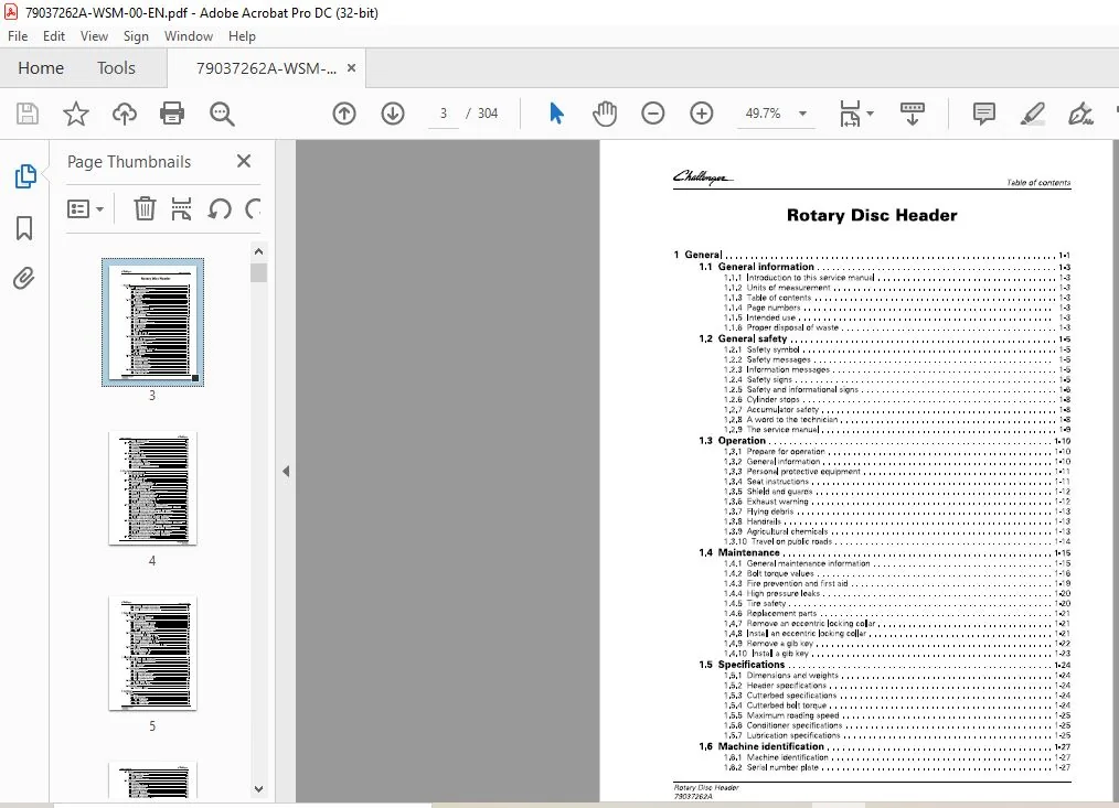
TABLE OF CONTENTS:
Challenger EU Hay Equipment 9295 9296 Rotary Disc Header Workshop Service Manual 79037262A – PDF DOWNLOAD
1 General 1-1
1 1 General information 1-3
1 1 1 Introduction to this service manual 1-3
1 1 2 Units of measurement 1-3
1 1 3 Table of contents 1-3
1 1 4 Page numbers 1-3
1 1 5 Intended use 1-3
1 1 6 Proper disposal of waste 1-3
1 2 General safety 1-5
1 2 1 Safety symbol 1-5
1 2 2 Safety messages 1-5
1 2 3 Information messages 1-5
1 2 4 Safety signs 1-5
1 2 5 Safety and informational signs 1-6
1 2 6 Cylinder stops 1-8
1 2 7 Accumulator safety 1-8
1 2 8 A word to the technician 1-8
1 2 9 The service manual 1-9
1 3 Operation 1-1 o
1 3 1 Prepare for operation 1-10
1 3 2 General information 1-10
1 3 3 Personal protective equipment 1-1 1
1 3 4 Seat instructions 1-1 1
1 3 5 Shield and guards 1-1 2
1 3 6 Exhaust warning 1-1 2
1 3 7 Flying debris 1-1 3
1 3 8 Handrails 1-1 3
1 3 9 Agricultural chemicals 1-1 3
1 3 10 Travel on public roads 1-1 4
1 4 Maintenance 1-15
1 4 1 General maintenance information 1-1 5
1 4 2 Bolt torque values 1-1 6
1 4 3 Fire prevention and first aid 1-1 9
1 4 4 High pressure leaks 1-20
1 4 5 Tire safety 1-20
1 4 6 Replacement parts 1-21
1 4 7 Remove an eccentric locking collar 1-21
1 4 8 Install an eccentric locking collar 1-21
1 4 9 Remove a gib key 1-22
1 4 10 Install a gib key 1-23
1 5 Specifications 1-24
1 5 1 Dimensions and weights 1-24
1 5 2 Header specifications 1-24
1 5 3 Cutterbed specifications 1-24
1 5 4 Cutterbed bolt torque 1-24
1 5 5 Maximum reading speed 1-25
1 5 6 Conditioner specifications 1-25
1 5 7 Lubrication specifications 1-25
1 6 Machine identification 1-27
1 6 1 Machine identification 1-27
1 6 2 Serial number plate 1-27
Rotary Disc Header
79037262A
Table of contents
1 6 3 Serial number description 1-2 7
1 7 Machine description 1-29
1 7 1 Description 1-2 9
1 7 2 Cutterbed 1-2 9
1 7 3 Conditioner 1-2 9
1 7 4 Swathboard 1-3 0
1 7 5 Forming shields 1-3 0
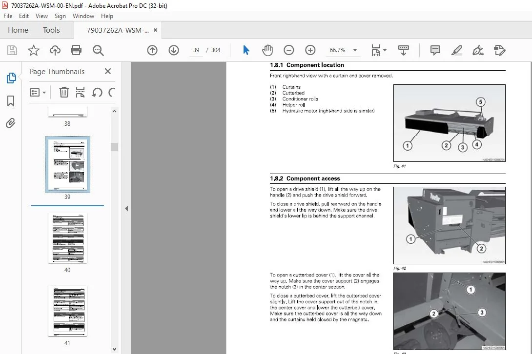
1 8 Component location 1-31
1 8 1 Component location 1-3 1
1 8 2 Component access 1-3 1
1 9 Troubleshooting 1-32
1 9 1 Header troubleshooting 1-3 2
1 9 2 Cutterbed troubleshooting 1-3 3
1 9 3 Conditioner troubleshooting 1-3 4
1 9 4 Crop conditioning and windrow formation 1-3 5
1 9 5 Cutoff quality 1-3 5
2 Drive system 2-1
2 1 Conditioner drive belt 2-3
2 1 1 Banded drive belt 2-3
2 1 2 Install a belt 2-3
2 1 3 Belt run-in procedure 2-4
2 2 Center cage spindle 2-6
2 2 1 Remove the center cage spindle 2-6
2 2 2 Disassemble the center cage spindle 2-6
2 2 3 Assemble the center cage spindle 2-7
2 2 4 Install the center cage spindle 2-8
2 3 Header drive gearbox – left 2-9
2 3 1 Header drive motor and gearbox – left side components 2-9
2 3 2 Special tools (header drive gearbox) 2-1 2
2 3 3 Remove the header drive gearbox – left 2-1 2
2 3 4 Disassemble the header drive gearbox – left 2-1 6
2 3 5 Examine the header drive gearbox 2-2 0
2 3 6 Assemble the header drive gearbox – left 2-2 1
2 3 7 Install the header drive gearbox – left 2-2 7
2 3 8 Adjust the header drive gearbox – left 2-3 3
2 4 Header drive gearbox – right (single conditioner) 2-36
2 4 1 Header drive motor and gearbox – right side components (single conditioner) 2-3 6
2 4 2 Special tools (header drive gearbox) 2-3 8
2 4 3 Remove the header drive gearbox – right (single conditioner) 2-3 8
2 4 4 Disassemble the header drive gearbox – right (single conditioner) 2-4 1
2 4 5 Examine the header drive gearbox 2-4 2
2 4 6 Assemble the header drive gearbox – right (single conditioner) 2-4 3
2 4 7 Install the header drive gearbox – right (single conditioner) 2-4 5
2 4 8 Adjust the header drive gearbox – right (single conditioner) 2-4 8
2 5 Header drive gearbox – right (double conditioner) 2-51
2 5 1 Header drive motor and gearbox – right side components (double conditioner) 2-5 1
2 5 2 Special tools (header drive gearbox) 2-5 4
2 5 3 Remove the header drive gearbox – right (double conditioner) 2-5 4
2 5 4 Disassemble the header drive gearbox – right, double conditioner machines 2-5 8
2 5 5 Examine the header drive gearbox 2-6 2
2 5 6 Assemble the header drive gearbox – right (double conditioner) 2-6 3
2 5 7 Install the header drive gearbox – right (double conditioner) 2-6 9
2 5 8 Adjust the header drive gearbox – right (single conditioner) 2-7 4
2 6 Conditioner drive tensioner 2-76
2 6 1 Header drive tensioner components 2-7 6
Rotary Disc Header
79037262A
Table of contents
2 6 2 Disassemble the header drive tensioner 2-77
2 6 3 Examine the conditioner drive tensioner 2-77
2 6 4 Assemble the conditioner drive tensioner 2-78
3 Hydraulic system 3-1
3 1 General information 3-3
3 1 1 General hydraulic information 3-3
3 1 1 1 Hydraulic system 3-3
3 2 Header drive motor 3-4
3 2 1 Header drive motor components 3-4
3 2 2 Examine the case drain leakage 3-5
3 2 3 Remove the header drive motor 3-7
3 2 4 Disassemble the header drive motor 3-9
3 2 5 Assemble the header drive motor 3-1 6
3 2 6 Install the header drive motor 3-2 5
3 3 Conditioner roll cylinders 3-29
3 3 1 Conditioner roll cylinder components 3-29
3 3 2 Remove the conditioner roll cylinders 3-29
3 3 3 Disassemble the conditioner roll cylinder 3-30
3 3 4 Examine the conditioner roll cylinder 3-30
3 3 5 Assemble the conditioner roll cylinder 3-3 1
3 3 6 Install the conditioner roll cylinder 3-3 1
3 3 7 Adjust the pressure of the conditioner roll cylinders 3-3 2
3 4 Accumulator 3-33
3 4 1 Remove the accumulator 3-3 3
3 4 2 Discharge the accumulator 3-3 3
3 4 3 Charge the accumulator 3-3 4
3 4 4 Install the accumulator 3-3 4
4 Electrical system 4-1
4 1 Basic electrical troubleshooting 4-3
4 1 1 Basic troubleshooting procedures 4-3
4 1 2 Tools 4-4
4 1 3 Continuity check 4-4
4 1 4 Voltage check 4-5
4 2 Connectors 4-6
4 2 1 Examine a connector 4-6
4 2 2 Pins and sockets 4-6
4 2 3 Replace a Packard connector 4-7
4 2 4 Replace an AMP connector 4-8
4 2 5 Replace a Power Cord connector 4-8
4 2 6 Replace a Deutsch connector 4-8
4 3 Header speed sensor 4-1 o
4 3 1 Electrical sensor location 4-10
4 3 2 Adjust the electrical sensors 4-10
4 4 Lighting 4-11
4 4 1 Examine the lighting 4-1 1
5 Cutterbed 5-1
5 1 Discs 5-3
5 1 1 Discs 5-3
5 1 2 Disc maintenance 5-3
5 1 3 Remove an inner disc 5-3
5 1 4 Install an inner disc 5-4
5 1 5 Remove the outer disc 5-4
5 1 6 Install the outer disc 5-6
Rotary Disc Header
79037262A
Table of contents
5 2 Knives 5-9
5 2 1 Knife wedging under disc 5-9
5 2 2 Knife inspection 5-9
5 2 3 Replace a knife 5-1 0
5 2 4 Knife hardware inspection 5-1 0
5 3 Cutterbed 5-12
5 3 1 Cutterbed 5-1 2
5 3 2 Cutterbed oil level 5-1 2
5 3 3 Change the cutterbed oil 5-1 2
5 3 4 Cutterbed inspection 5-1 4
5 3 5 Cutterbed components 5-1 5
5 3 6 Remove the cutterbed 5-1 6
5 3 7 Disassemble the cutterbed 5-1 8
5 3 8 Examine the cutterbed 5-1 9
5 3 9 Assemble the cutterbed 5-2 0
5 3 10 Examine the cutterbed for leaks 5-2 2
5 3 1 1 Install the cutterbed 5-2 3
5 4 Spindle gear assembly 5-26
5 4 1 Spindle gear assembly 5-2 6
5 4 2 Remove the spindle gear 5-2 6
5 4 3 Disassemble the spindle gear 5-2 7
5 4 4 Examine the spindle gear 5-2 7
5 4 5 Assemble the spindle gear 5-2 8
5 4 6 Install the spindle gear 5-2 9
5 5 Idler gear assembly 5-31
5 5 1 Idler gear assembly 5-3 1
5 5 2 Remove the idler gear 5-3 1
5 5 3 Disassemble the idler gear 5-3 3
5 5 4 Examine the idler gear 5-3 4
5 5 5 Assemble the idler gear 5-3 4
5 5 6 Install the idler gear 5-3 5
6 Conditioner 6-1
6 1 Helper roll 6-3
6 1 1 Helper roll components 6-3
6 1 2 Remove the helper roll 6-3
6 1 3 Install the helper roll 6-7
6 2 Auger strippers 6-12
6 2 1 Adjust the auger strippers 6-1 2
6 3 Drive shaft 6-13
6 3 1 Remove the drive shaft – slip tube 6-1 3
6 3 2 Install the drive shaft – slip tube 6-1 4
6 3 3 Remove the drive shaft – solid shaft 6-1 6
6 3 4 Install the drive shaft – solid shaft 6-1 6
6 4 U-joint 6-18
6 4 1 U-joint components 6-1 8
6 4 2 Remove the U-joints 6-1 8
6 4 3 Disassemble the U-joint 6-1 9
6 4 4 Assemble the U-joint 6-2 1
6 4 5 Install the U-joints 6-2 7
6 5 Belts 6-29
6 5 1 Belt maintenance 6-2 9
6 5 2 Replace the conditioner belt 6-2 9
6 5 3 Adjust the conditioner belt 6-3 0
6 6 Left conditioner gearbox 6-31
6 6 1 Conditioner gearbox lubrication 6-3 1
Rotary Disc Header
79037262A
Table of contents
6 6 2 Remove the left conditioner gearbox 6-31
6 6 3 Conditioner gearbox components – left 6-31
6 6 4 Disassemble the left conditioner gearbox 6-32
6 6 5 Examine the conditioner gearbox 6-33
6 6 6 Assemble the left conditioner gearbox 6-34
6 6 7 Install the left conditioner gearbox 6-35
6 7 Right conditioner gearbox 6-36
6 7 1 Conditioner gearbox lubrication 6-36
6 7 2 Remove the right conditioner gearbox 6-36
6 7 3 Conditioner gearbox components – right 6-36
6 7 4 Disassemble the right conditioner gearbox 6-37
6 7 5 Examine the conditioner gearbox 6-38
6 7 6 Assemble the right conditioner gearbox 6-38
6 7 7 Install the right conditioner gearbox 6-39
6 8 Conditioner bearings 6-40
6 8 1 Remove a spherical bearing 6-40
6 8 2 Install a spherical bearing 6-41
6 8 3 Remove a bushing bearing 6-42
6 8 4 Install a bushing bearing 6-42
6 9 Rear conditioner – double conditioner only 6-44
6 9 1 Rear top conditioner – components (double conditioner) 6-44
6 9 2 Remove the rear top conditioner – double conditioner 6-45
6 9 3 Install the rear top conditioner roll – double conditioner 6-46
6 9 4 Rear bottom conditioner components – double conditioner 6-49
6 9 5 Remove the rear bottom conditioner – double conditioner 6-49
6 9 6 Install the rear bottom conditioner – double conditioner 6-51
6 1 0 Front conditioner 6-53
6 10 1 Front top conditioner – components 6-53
6 10 2 Remove the front top conditioner 6-54
6 10 3 Install the front top conditioner 6-55
6 10 4 Front bottom conditioner – components 6-56
6 10 5 Remove the front bottom conditioner 6-56
6 10 6 Install the front bottom conditioner 6-58
6 1 1 Conditioner adjustments 6-61
6 1 1 1 Examine the conditioner 6-6 1
6 1 1 2 Conditioner 6-6 1
6 1 1 3 Conditioner spacing 6-6 1
6 1 1 3 1 Adjust the conditioner roll spacing 6-6 1
6 1 1 4 Conditioner spacing indicator 6-6 2
6 1 1 4 1 Adjust the conditioner spacing indicator – double conditioner 6-6 2
6 1 1 4 2 Adjust the conditioner spacing indicator – single conditioner 6-6 3
6 1 1 5 Adjust the conditioner timing 6-6 3
6 1 1 6 Conditioner pressure 6-6 4
6 1 1 7 Adjust the conditioner pressure 6-6 4
6 1 2 Windrow forming shields 6-65
6 1 2 1 Adjust the windrow forming shields 6-6 5
6 1 2 2 Adjust the deflector 6-6 5
6 1 2 3 Adjust the windrow forming deck height 6-6 5
6 1 3 Swathboard 6-67
6 1 3 1 Swathboard 6-6 7
6 1 3 2 Adjust the swathboard 6-6 7
7 Diagrams 7-1
7 1 Reading wiring diagrams 7-3
7 1 1 Diagram numbers 7-3
7 1 2 Location grids 7-3
7 1 3 Wire breaks 7-4
Rotary Disc Header
79037262A
Table of contents
7 2 Diagram symbols and abbreviations 7-6
7 2 1 Harness and connector identification 7-6
7 2 2 Splices 7-6
7 2 3 CAN signal 7-7
7 3 Electrical diagrams 7-8
7 3 1 Harness abbreviations 7-8
7 3 2 Wire col ors 7-8
7 3 3 Main electrical diagram 7-9
7 4 Electrical tables 7-11
7 4 1 Circuit table 7-1 1
7 4 2 Connector function 7-1 3
7 4 3 Connector table 7-1 3
7 4 4 Tractor connector 7-1 4
7 5 Hydraulic schematic 7-16
7 5 1 Hy draulic schematic 7-1 7
8 Index lndex-1
CHALLENGER EU HAY EQUIPMENT 9295 9296 ROTARY DISC HEADER WORKSHOP SERVICE MANUAL 79037262A:
PLEASE NOTE:
- This is the SAME exact manual used by your dealers to fix your vehicle.
- The same can be yours in the next 2-3 mins as you will be directed to the download page immediately after paying for the manual.
- Any queries / doubts regarding your purchase, please feel free to contact [email protected]
S.V