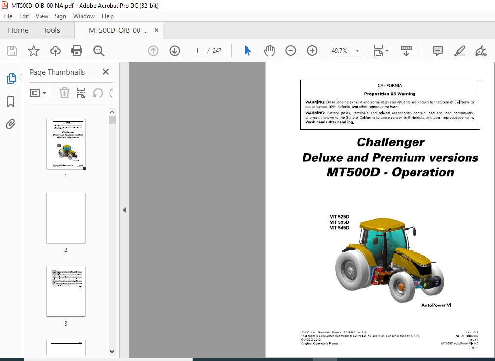
Challenger MT500D Series MT 525D MT 535D MT 545D AutoPower VI Operator Instruction Manual
Original price was: $89.95.$25.95Current price is: $25.95.
Challenger MT500D Series MT 525D MT 535D MT 545D Deluxe & Premium Versions AutoPower VI Operator Instruction Manual ACT0000840 – PDF DOWNLOAD
Description
Challenger MT500D Series MT 525D MT 535D MT 545D Deluxe & Premium Versions AutoPower VI Operator Instruction Manual ACT0000840 – PDF DOWNLOAD
CHALLENGER MT500D SERIES MT 525D MT 535D MT 545D AUTOPOWER VI OPERATOR INSTRUCTION MANUAL:
IMAGES PREVIEW OF THE MANUAL:


DESCRIPTION:
Challenger MT500D Series MT 525D MT 535D MT 545D Deluxe & Premium Versions AutoPower VI Operator Instruction Manual ACT0000840 – PDF DOWNLOAD
Foreword :
We would like to welcome you to the ever-growing number of people who own a Challenger tractor; people who appreciate quality. We are proud of every tractor that leaves our factories, each being technically advanced and of high quality. This Operator’s Manual contains the specifications for your new tractor. Please ensure that all operators read the instructions and follow them carefully.
- The pages that follow contain vital information on your tractor; please read them carefully. Your Challenger dealer will guarantee you quality servicing and will provide you with all the assistance you need. When it comes to servicing, remember that your dealer knows your tractor best and that he wants you to be completely satisfied.
- Please leave this Operator’s Manual in the tractor if resold. The subsequent owner will need the information it contains. All information and specifications in this manual are up to date at the time of publication.
- However, our ongoing policy to improve our products obliges us to reserve the right to make alterations at any time without notice. Please note that this manual relates to all models and refers to both standard and optional equipment. You may therefore find details relating to equipment that is not fitted on your tractor. This Operator’s Manual complies with Directive 2010/52 EC.
Operator’s Manual :
- The purpose of this manual is to еnаЫе the owner and the operator to operate the tractor appropriately under normal conditions of use. Providing they follow the instructions carefully, the tractor will give many years of service in the Challenger tradition. Use for any other activity (particularly forestry work) is considered to Ье contrary to the intended use. The commissioning of equipment Ьу the Challenger dealer оп the user’s premises enaЫes the dealer to ensure that these operating and service instructions are properly understood.
- Always consult the Challenger dealer if there is any part of this manual that you do not understand. lt is important that these instructions are understood and followed. This manual does not cover all operation and safety instructions relevant to the implements and accessories that may Ье fitted at the time of tractor delivery or later. lt is essential that operators use and understand the Operator’s Manuals relating to these implements and accessories.
IMPORTANT:
- This manual must always Ье kept with the tractor. For extra copies, contact your Challenger dealer. This chapter in the Operator’s Manual highlights certain basic safety-related situations that may Ье encountered during normal operation and servicing of the tractor and provides the information needed to handle these situations. This chapter supplements any safety instructions given in other chapters of this manual.
- lt may Ье necessary to take additional precautions, depending оп the implements and accessories used and the working conditions on-site or in the service area. Challenger сап under по circumstances exercise direct control over the commissioning, operation, inspection, lubrication or servicing of the tractor. lt is therefore YOUR responsibility to take suitaЫe safety precautions in such areas.
TABLE OF CONTENTS:
Challenger MT500D Series MT 525D MT 535D MT 545D Deluxe & Premium Versions AutoPower VI Operator Instruction Manual ACT0000840 – PDF DOWNLOAD
1 Tractor identification 9
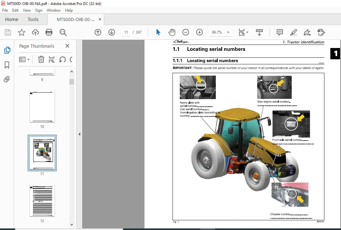
1 1 Locating serial numbers 11
1 1 1 Locating serial numbers 11
1 2 Your tractor identification details 12
1 2 1 Your tractor identification details 12
2 Safety instructions and safety points – Warranty 13
2 1 Introduction 15
2 1 1 Introduction – Safety instructions 15
2 2 Safety – Symbols and terms 17
2 2 1 Safety – Symbols and terms 17
2 3 Safety signs and instructions 18
2 3 1 Checking and replacing the safety signs and instructions 18
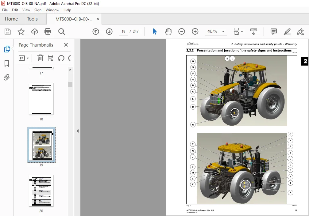
2 3 2 Presentation and location of the safety signs and instructions 19
2 4 General safety instructions 24
2 4 1 Awareness of the safety instructions and symbols 24
2 4 2 Operator familiarity in the use of the tractor 24
2 4 3 Filling the fuel tank 25
2 4 4 Getting into and out of the cab 26
2 4 5 Mandatory procedure before dismounting the tractor 26
2 5 Special safety instructions for preparing the tractor for use 27
2 5 1 Protective clothing 27
2 5 2 Activated carbon filter information 27
2 5 3 Safety devices and items 29
2 5 4 Checking the tractor 30
2 6 Specific safety instructions for starting the tractor 32
2 6 1 Protection of persons other than the operator 32
2 6 2 Start up safely 32
2 6 3 Checks to be carried out after start-up 33
2 7 Specific safety instructions for using the tractor 34
2 7 1 General instructions 34
2 7 2 Protection of persons other than the operator 35
2 7 3 Overturning 35
2 7 4 Tractor towing 38
2 7 5 Road use 38
2 7 6 Power take-off 39
2 7 7 Implements 40
2 7 8 Front-end loader 43
2 8 Specific safety instructions for servicing the tractor 44
2 8 1 Pollution warning to observe when servicing the tractor 44
2 8 2 General instructions 44
2 8 3 Handling instructions 45
2 8 4 Special instructions for cleaning the tractor 47
2 9 Protective structures 48
2 9 1 Protective structures: use and accreditation 48
2 9 2 Cab or ROPS (depending on model) 48
2 9 3 Seat belt 48
2 9 4 Instructor seat 49
MT500D AutoPower VI – NA
ACT0000840 – 1
5
Table of contents
2 10 Warranty 50
2 10 1 General 50
2 10 2 Pre-delivery inspection and commissioning at the user’s premises 50
2 10 3 Warranty procedure 50
2 10 4 Procedure to follow if changing region 50
2 10 5 Servicing during and after the warranty period 51
2 10 6 California emission control warranty statement 51
2 10 7 California emission reduction control warranty for the United States and
Canada 54
3 Operation 59
3 1 Cab 63
3 1 1 Steering console 63
3 1 2 Instrument panel 64
3 1 3 Control unit 69
3 1 4 Pedals 69
3 1 5 Steering Wheel 70
3 1 6 Operator presence detector 71
3 1 7 Automatic adjustment pneumatic seat 73
3 1 8 Right-hand console 81
3 1 9 Armrest TMC Armrest 81
3 1 10 Right-hand pillar 84
3 1 11 Left-hand console 85
3 1 12 Upper console 85
3 1 13 Air conditioning 86
3 1 14 Additional heater 92
3 1 15 Accessories sockets 93
3 1 16 Emergency exits 93
3 1 17 Cab safety 94
3 1 18 Sun visor 95
3 1 19 Wheel chock(s) (optional) 95
3 2 TMC Dash Display control screens on the instrument panel 97
3 2 1 Using the Dash Control Center screen 97
3 2 2 TMC Dash Display screens 97
3 3 Body 102
3 3 1 Opening the hood 102
3 3 2 Adjusting the external rear-view mirrors 103
3 4 Engine 105
3 4 1 Running-in 105
3 4 2 Filling with fuel 105
3 4 3 Start switch 107
3 4 4 Start-up 108
3 4 5 Start-up sheet 109
3 4 6 Cold weather starting 110
3 4 7 Information about the various operating modes of the e3 SCR Technology
engine 111
3 4 8 Stopping the engine 114
3 4 9 Engine speed 114
3 5 Transmission 116
3 5 1 Presentation of the different driving modes 116
3 5 2 Clutch function 116
3 5 3 PowerShuttle 116
3 5 4 Adjusting the start ratios (1A, 1 B, 1 C, etc ) 119
3 5 5 Storing the transmission ratios (1A, 1 B, 1 C, etc ) 121
3 5 6 Lever mode (Speedmatching) 123
3 5 7 Pedal mode (AutoDrive) 126
3 5 8 road mode (hare)/field mode (tortoise) 129
6 MT500D AutoPower VI – NA
ACT0000840 – 1
C? Table of contents
3 5 9 Changing the transmission ratios (1A, 18, 1C etc ) 131
3 5 10 Optional creeper range (snail) 131
3 5 11 Tractor towing 132
3 5 12 Forward speed calibration 132
3 6 Brakes 134
3 6 1 Brake pedals 134
3 6 2 Hydraulic trailer brake 134
3 6 3 Pneumatic trailer brake 135
3 6 4 Parking brake 137
3 7 Steering 138
3 7 1 Steering 138
3 8 Front axle 141
3 8 1 Four-wheel drive front axle 141
3 8 2 Suspended front axle 142
3 9 Differential lock 144
3 9 1 Differential lock 144
3 10 Power take-off 146
3 10 1 Front power take-off 146
3 10 2 Rear power take-off (PTO) 147
3 10 3 Economy PTO 151
3 10 4 Proportional PTO (optional) 151
3 10 5 Changing the flanged shaft 152
3 10 6 Replacing the interchangeable shaft 153
3 10 7 PTO external control 154
3 10 8 Power take-off electronic controls 155
3 10 9 Power take-off protection 156
3 11 Linkage 157
3 11 1 General 157
3 11 2 Rear linkage electronic controls 158
3 11 3 Rear linkage operation 159
3 11 4 Rear linkage external controls 166
3 11 5 Front linkage 167
3 11 6 Top link 171
3 11 7 Bottom links 173
3 11 8 Lift rods 175
3 11 9 Stabilizers 176
3 11 10 Ball joint support 180
3 12 Towing equipment 181
3 12 1 General 181
3 12 2 Swinging drawbar 182
3 12 3 Three-point linkage Quick linkage hitch 185
3 13 Auxiliary hydraulics 187
3 13 1 General 187
3 13 2 Description of hydraulic couplers on Closed Center system (Load Sensing) 187
3 13 3 Use of hydraulic couplers on Closed Center system (Load Sensing) 191
3 13 4 Locking/unlocking the controls 196
3 13 5 Description and use of the cab controls 197
3 13 6 Hydraulics control lever 201
3 13 7 Setting flow rates and time delay 203
3 13 8 Emergency manual spool valve control 204
3 14 Front-end loader function 205
3 14 1 Front-end loader 205
3 14 2 Layout of components 205
3 14 3 Using the front-end loader controls 206
3 15 Lighting 211
3 15 1 Main lighting control module 211
3 15 2 Right-hand pillar, work lights module 212
MT500D AutoPower VI – NA
ACT0000840 – 1
7
Table of contents
3 16 Suspended cab 213
3 16 1 Suspended cab 213
3 17 Front tires and track widths 215
3 17 1 Wheel studs 215
3 17 2 Installation points of the axle stands 215
3 17 3 Adjusting the front wheel track width 216
3 17 4 Adjusting the 4WD front axle stops 219
3 17 5 Tires 221
3 17 6 Tire pressures 221
3 18 Rear tires and track widths 222
3 18 1 Wheel studs 222
3 18 2 Installation points of the axle stands 222
3 18 3 Rear track width with flanged shafts 223
3 18 4 Rear track width with short straight shafts 225
3 18 5 Rear track width with long straight shafts 229
3 18 6 Adjusting the rear wheel track width 234
3 19 Dual wheels 236
3 19 1 Dual wheels 236
3 19 2 Installation points of the axle stands 237
3 19 3 Dual rear wheel track width with long straight shafts 238
3 19 4 Adjusting the rear wheel track width 245
3 20 Ballast 247
3 20 1 Liquid ballasting 247
PLEASE NOTE:
- This is the SAME exact manual used by your dealers to fix your vehicle.
- The same can be yours in the next 2-3 mins as you will be directed to the download page immediately after paying for the manual.
- Any queries / doubts regarding your purchase, please feel free to contact [email protected]
S.V