Challenger MT500E Series MT 515E MT 525E MT 535E MT 545E Classic Version Operator’s Manual
Original price was: $89.95.$25.95Current price is: $25.95.
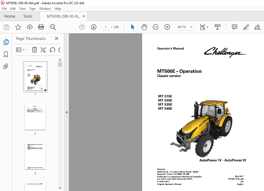
Challenger MT500E Series MT 515E MT 525E MT 535E MT 545E Classic Version AutoPower IV – AutoPower VI Operator’s Manual ACT001131B – PDF DOWNLOAD
Description
Challenger MT500E Series MT 515E MT 525E MT 535E MT 545E Classic Version AutoPower IV – AutoPower VI Operator’s Manual ACT001131B – PDF DOWNLOAD
CHALLENGER MT500E SERIES MT 515E MT 525E MT 535E MT 545E CLASSIC VERSION OPERATOR’S MANUAL:
IMAGES PREVIEW OF THE MANUAL:


FILE DETAILS:
Challenger MT500E Series MT 515E MT 525E MT 535E MT 545E Classic Version AutoPower IV – AutoPower VI Operator’s Manual ACT001131B – PDF DOWNLOAD
Size : 35.6 MB
Format : PDF
Language : English
Brand: Challenger EU
Type of machine: Agricultural-Tractor
Type of document: Operation Manual
Model: Challenger EU Tractor MT515E MT525E MT535E MT545E AutoPower IV-VI Classic
Date: 2017
Number of Pages: 246 Pages
Part Number: ACT001131B
DESCRIPTION:
Challenger MT500E Series MT 515E MT 525E MT 535E MT 545E Classic Version AutoPower IV – AutoPower VI Operator’s Manual ACT001131B – PDF DOWNLOAD
Operator’s Manual :
- The purpose of this manual is to еnаЫе the owner and the operator to operate the tractor appropriately under normal conditions of use. Providing they follow the instructions carefully, the tractor will give many years of service in the Challenger tradition. Use for any other activity (particularly forestry work) is considered to Ье contrary to the intended use. The commissioning of equipment Ьу the Challenger dealer оп the user’s premises enaЫes the dealer to ensure that these operating and service instructions are properly understood.
- Always consult the Challenger dealer if there is any part of this manual that you do not understand. lt is important that these instructions are understood and followed. This manual does not cover all operation and safety instructions relevant to the implements and accessories that may Ье fitted at the time of tractor delivery or later. lt is essential that operators use and understand the Operator’s Manuals relating to these implements and accessories.
IMPORTANT:
- This manual must always Ье kept with the tractor. For extra copies, contact your Challenger dealer. This chapter in the Operator’s Manual highlights certain basic safety-related situations that may Ье encountered during normal operation and servicing of the tractor and provides the information needed to handle these situations. This chapter supplements any safety instructions given in other chapters of this manual.
- lt may Ье necessary to take additional precautions, depending оп the implements and accessories used and the working conditions on-site or in the service area. Challenger сап under по circumstances exercise direct control over the commissioning, operation, inspection, lubrication or servicing of the tractor. lt is therefore YOUR responsibility to take suitaЫe safety precautions in such areas.
TABLE OF CONTENTS:
Challenger MT500E Series MT 515E MT 525E MT 535E MT 545E Classic Version AutoPower IV – AutoPower VI Operator’s Manual ACT001131B – PDF DOWNLOAD
1 Tractor identification 11
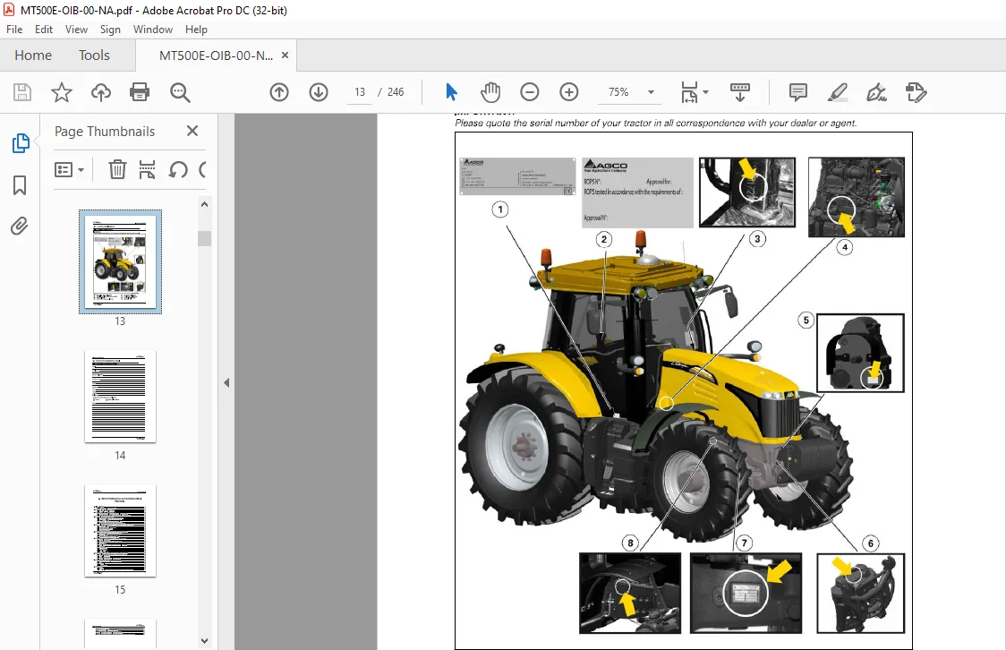
1 1 Locating serial numbers 13
1 1 1 Locating serial numbers 13
1 2 Your tractor identification details 14
1 2 1 Your tractor identification details 14
2 Safety instructions and safety points – Warranty 15
2 1 Introduction 17
2 1 1 Introduction – Safety instructions 17
2 2 Safety – Symbols and terms 19
2 2 1 Safety – Symbols and terms 19
2 3 Safety decals and instructions 20
2 3 1 Checking and replacing the safety decals and instructions 2 0
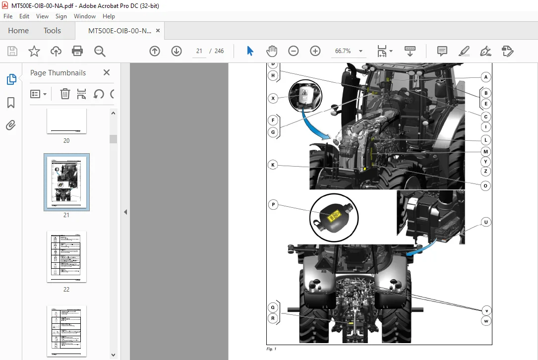
2 3 2 Presentation and location of the safety decals and instructions 2 1
2 4 General safety instructions 26
2 4 1 Awareness of the safety instructions and symbols 2 6
2 4 2 Operator familiarity in the use of the tractor 2 6
2 4 3 Filling the fuel tank 2 7
2 4 4 Mounting and dismounting the operator’s seat 2 7
2 4 5 Mandatory procedure before dismounting the tractor 2 8
2 5 Special safety instructions for preparing the tractor for use 29
2 5 1 Protective clothing 2 9
2 5 2 Activated carbon filter information 2 9
2 5 3 Safety devices and items 3 2
2 5 4 Checking the tractor 3 2
2 6 Specific safety instructions for starting the tractor 34
2 6 1 Protection of persons other than the operator 3 4
2 6 2 Start up safely 3 4
2 6 3 Starting the tractor with jump start cables 3 5
2 6 4 Checks to be carried out after start-up 3 6
2 7 Specific safety instructions for using the tractor 37
2 7 1 General instructions 3 7
2 7 2 Protection of persons other than the operator 3 8
2 7 3 Overturning 3 8
2 7 4 Tractor towing 4 1
2 7 5 Regulatory data on maximum permitted trailed weights 4 1
2 7 6 Road use 4 3
2 7 7 Parking brake 4 5
2 7 8 Power take-off 4 5
2 7 9 Implements 4 6
2 7 10 Front-end loader 4 8
2 8 Specific safety instructions for servicing the tractor 49
2 8 1 Pollution warning to observe when servicing the tractor 4 9
2 8 2 General instructions 4 9
2 8 3 Handling instructions 5 0
2 8 4 Special instructions for cleaning the tractor 5 2
2 9 Protective structures 53
2 9 1 Protective structures – Use and accreditation 5 3
2 9 2 Cab 5 3
2 9 3 Seat belt 5 3
MT500E – Operation
ACTOOJ 131 B_ed3
Table of contents
2 9 4 Instructor seat 5 4
2 10 Warranty 55
2 10 1 General 5 5
2 10 2 Pre-delivery inspection and commissioning on the user’s premises 5 5
2 10 3 Warranty procedure 5 5
2 10 4 Procedure to follow if changing region 5 5
2 10 5 Servicing during and after the warranty period 5 6
2 10 6 California emission control warranty statement 5 6
2 10 7 Emission reduction warranty statement for the United States and Canada 5 9
3 Usage 65
3 1 Standard cab 69
3 1 1 Steering console 6 9
3 1 2 Instrument panel 7 0
3 1 3 Control unit 7 6
3 1 4 Pedals 7 7
3 1 5 Steering wheel 7 7
3 1 6 Operator presence detector 7 8
3 1 7 Automatic adjustment pneumatic seat 8 1
3 1 8 Manual adjustment pneumatic seat 8 7
3 1 9 Instructor seat 9 2
3 1 10 Right-hand console 9 2
3 1 11 Right-hand pillar 9 3
3 1 12 Left-hand console 9 3
3 1 13 Upper console 9 4
3 1 14 Manual air conditioning 9 5
3 1 15 Additional heater 9 9
3 1 16 Accessories sockets 10 0
3 1 17 Emergency exits 10 0
3 1 18 Sun visor 10 1
3 1 19 Wheel chock(s) (optional) 10 1
3 2 Setup and Information Screen control screens on the instrument
panel 103
3 2 1 Using the Setup and Information Screen 10 3
3 2 2 Setup and Information screens 10 5
3 3 Body 112
3 3 1 Opening the bonnet 112
3 3 2 Adjusting the external rear-view mirrors 112
3 3 2 1 Positioning the arms 112
3 3 2 2 Adjusting the arm extensions (depending on model) 113
3 3 2 3 Adjusting the rear-view mirrors (depending on model) 113
3 4 Engine 114
3 4 1 Running-in 114
3 4 2 Filling with fuel 114
3 4 3 Start switch 116
3 4 4 Start-up 116
3 4 5 Starting the SCR Technology engine in cold weather 117
3 4 6 Information about the various operating modes of the SCR Technology engine 119
3 4 7 Stopping the engine 12 4
3 4 8 Engine speed 12 4
3 4 9 Storing an engine speed 12 6
3 5 Transmission 128
3 5 1 Presentation of the different driving modes 12 8
3 5 2 Clutch function 12 8
3 5 3 PowerShuttle 12 9
3 5 3 1 PowerShuttle Protection Function 13 0
3 5 4 Adjusting the start ratios ( 1A, 1B , 1C etc ) 13 1
MT500E – Operation
ACT001131 B_ed3
Table of contents
3 5 4 1 Setting procedure: 13 1
3 5 4 2 Starting ratio 13 1
3 5 5 Lever (Speedmatching) mode 13 2
3 5 6 Pedal (AutoDrive) mode 13 3
3 5 7 Road mode ( Hare)/Field mode (Tortoise) 13 4
3 5 8 Changing the transmission ratios ( 1A , 1B , 1C , etc ) 13 5
3 5 9 Optional creeper range (snail) 13 6
3 5 10 Tractor towing 13 6
3 5 11 Forward speed calibration 13 6
3 6 Brakes 138
3 6 1 Brake pedals 13 8
3 6 2 Hydraulic trailer brake 13 8
3 6 3 Pneumatic trailer brake 13 9
3 6 4 Parking brake 14 0
3 7 Front axle 142
3 7 1 Four-wheel drive front axle 14 2
3 7 2 Suspended front axle 14 3
3 7 3 Permissible load on the front axle 14 5
3 8 Differential lock 148
3 8 1 Differential lock 14 8
3 9 Power take-off 150
3 9 1 Front power take-off 15 0
3 9 2 Rear power take-off ( PTO) 15 0
3 9 2 1 Selecting the power take-off speed 15 1
3 9 2 2 Adjusting the progressivity of power-take-off engagement 15 2
3 9 2 3 Engaging PTO in manual mode: 15 3
3 9 2 4 Engaging PTO in automatic mode: 15 3
3 9 3 Economy PTO 15 4
3 9 4 GSPTO (optional) 15 5
3 9 5 Replacing the interchangeable shaft 15 6
3 9 6 Changing the flanged shaft 15 7
3 9 7 PTO external control 15 7
3 9 8 Power take-off electronic controls 15 8
3 9 9 Power take-off protection 15 8
3 1 O Linkage 1 so
3 10 1 General 16 0
3 10 2 Rear linkage electronic controls 16 1
3 10 3 Rear linkage operation 16 3
3 10 4 Rear linkage external controls 16 8
3 10 5 Front linkage 16 9
3 10 6 Top link 17 2
3 10 7 Bottom links 17 4
3 10 8 Lift rods 17 5
3 10 9 Stabilizers 17 6
3 10 9 1 Stabilizers with manual telescopic adjustment 17 6
3 10 9 2 Stabilizers with shoes 17 7
3 10 10 Ball joint support 17 8
3 11 Towing equipment 179
3 11 1 General 17 9
3 11 2 Swinging drawbar 18 1
3 11 2 1 Fitting the swinging drawbar 18 2
3 12 Auxiliary hydraulics 184
3 12 1 General 18 4
3 12 2 Description of hydraulic couplers on Open Center system 18 4
3 12 3 Use of hydraulic couplers on Open Center system 18 5
3 12 4 Description of hydraulic couplers on Closed Center system ( Load Sensing) 18 8
3 12 5 Use of hydraulic couplers on Closed Center system (Load Sensing) 19 0
MT500E – Operation
ACTOOJ 131 B_ed3
Table of contents
3 12 6 Description of the hydraulic controls inside the cab 19 4
3 12 7 Hydraulics control lever 19 5
3 12 8 Open Centre 10 0 1/min ( 2 6 4 gal/min ( US)) 19 6
3 12 8 1 Pump coupling (combined flow) 19 6
3 12 8 2 Pump uncoupling 19 7
3 12 9 Setting flow rates 19 7
3 13 Standard front-end loader function 198
3 13 1 Front-end loader 19 8
3 13 2 Layout of components 19 8
3 13 3 Standard front-end loader connection 19 9
3 13 4 Using the mechanical joystick of the front-end loader 2 0 0
3 13 4 1 Locking/unlocking the front-end loader control 2 0 0
3 13 4 2 Joystick in working position 2 0 0
3 13 4 3 Joystick in rest position 2 0 1
3 13 4 4 Joystick functions for the front-end loader 2 0 1
3 13 4 5 Electrical functions for the front-end loader 2 0 1
3 13 4 6 Floating position 2 0 2
3 13 4 7 3rd and 4th functions 2 0 2
3 13 4 8 Arm suspension 2 0 3
3 13 4 9 Locking and unlocking accessories 2 0 3
3 14 Lighting 204
3 14 1 Main lighting control module 2 0 4
3 14 2 Work lights module 2 0 5
3 14 3 Direction indicators 2 0 6
3 15 Suspended cab 2 10
3 15 1 Suspended cab 2 10
3 16 Front tires and track widths 2 13
3 16 1 Wheel studs 2 13
3 16 2 Installation points of the axle stands 2 13
3 16 3 Adjusting the front wheel track width 2 14
3 16 4 Adjusting the 4WD front axle stops 2 17
3 16 4 1 Fitting the oscillation stops 2 17
3 16 4 2 Adjusting the steering angle 2 17
3 16 4 3 Toe-in check 2 18
3 16 4 4 Adjusting the front fenders Shoe side adjustment on the front axle 2 18
3 16 4 5 Adjusting the front fenders Adjusting the lateral position of the fender
on the support (two adjustments are possible) 2 19
3 16 4 6 Adjusting the front fenders Adjusting the height of the support on the
shoe 2 19
3 16 5 Tires 2 19
3 16 6 Tire pressures 2 19
3 17 Rear tires and track widths 220
3 17 1 Wheel studs 2 2 0
3 17 2 Installation points of the axle stands 2 2 0
3 17 3 Rear track width with flanged shafts 2 2 1
3 17 4 Rear track width with short straight shafts 2 2 3
3 17 5 Rear track width with long straight shafts 2 2 6
3 17 6 Adjusting the rear wheel track width 2 2 9
3 17 6 1 Adjustment of wheel position on the straight shaft 2 2 9
3 17 6 2 Adjustment of wheel position on the straight shaft 2 3 0
3 18 Dual wheels 231
3 18 1 Dual wheels 2 3 1
3 18 2 Installation points of the axle stands 2 3 2
3 18 3 Dual rear wheel track width with long straight shafts 2 3 3
3 18 4 Adjusting the rear wheel track width 2 3 8
3 18 4 1 Adjustment of wheel position on the straight shaft 2 3 9
3 18 4 2 Adjustment of wheel position on the straight shaft 2 3 9
MT500E – Operation
ACT001131 B_ed3
Table of contents
3 19 Ballast 241
3 19 1 Liquid ballasting 241
3 19 2 Front-end weight 241
PLEASE NOTE:
- This is the SAME manual used by the dealers to troubleshoot any faults in your vehicle. This can be yours in 2 minutes after the payment is made.
- Contact us at [email protected] should you have any queries before your purchase or that you need any other service / repair / parts operators manual.
S.V