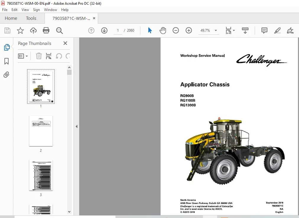
Challenger RG900B RG1100B RG1300B Applicator Chassis Workshop Service Manual
Original price was: $97.95.$33.95Current price is: $33.95.
Challenger RG900B RG1100B RG1300B Applicator Chassis Workshop Service Manual – PDF DOWNLOAD
Description
Challenger RG900B RG1100B RG1300B Applicator Chassis Workshop Service Manual – PDF DOWNLOAD
DESCRIPTION:
Challenger RG900B RG1100B RG1300B Applicator Chassis Workshop Service Manual – PDF DOWNLOAD
A word to the operator:
It is your responsibility to read and understand the safety section in this manual and the manual for all implements before you operate this machine. You are responsible for your safety. Good safety procedures prevent injury to you and the persons around you. Make the information in the safety section of this manual a part of your safety procedure. This safety section is written only for this type of machine. Safety is your responsibility. You can prevent injury and death.
- This safety section gives basic safety examples that can occur during the operation and maintenance of your machine. This safety section is not a replacement for safety instruction in other sections of this manual.
- Injury or death can occur if the safety instruction is not obeyed. Learn how to operate the machine and how to use the controls correctly. Do not operate the machine if you do not know how to operate the machine.
- Do not let persons operate the machine that do not know how to operate the machine. Follow all safety instructions in the manuals and on the safety signs on the machine, the implements, and the attachments. Use only approved attachments and implements. Make sure that your machine has the correct equipment that is necessary by the local regulations.
Prepare for operation:
Read and understand all operation instructions and precautions in this manual before you operate the machine or do the servicing. Make sure that you know and understand the positions and operations of all controls. Make sure that all controls are in neutral and that the parking brake is applied before you start the machine. Make sure that all persons are away from your area of work before you start and operate the machine.
- Examine and learn the controls in an area that is clear of persons and obstacles before you start work. Know the machine dimensions and make sure that you have sufficient space available to operate the machine.
- Do not operate the machine at high speeds in crowded areas. It is important to know and use the correct procedures when you do work around and operate the machine. Do not let children or unqualified persons operate the machine.
- Keep others, especially children, away from your area of work. Do not let others ride on the machine. Make sure that the machine is in good condition for operation. Refer to the operator manual. Make sure that the machine has the correct equipment required by local regulations.
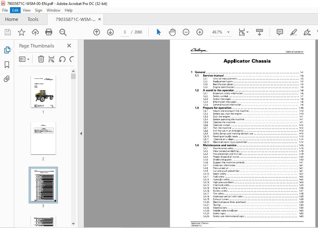
TABLE OF CONTENTS:
Challenger RG900B RG1100B RG1300B Applicator Chassis Workshop Service Manual – PDF DOWNLOAD
1 General 1-1
1 1 Service manual 1-3
1 1 1 Units of measurement 1-3
1 1 2 Replacement parts 1-3
1 1 3 Identification plates 1-3
1 1 4 Engine identification 1-5
1 2 A word to the operator 1-6
1 2 1 Important safety information 1-6
1 2 2 Safety symbol 1-7
1 2 3 Safety messages 1-8
1 2 4 Information messages 1-8
1 2 5 General hazard information 1-8
1 3 Prepare for operation 1-10
1 3 1 Mount and dismount the machine 1-10
1 3 2 Before you start the engine 1-10
1 3 3 Start the engine 1-1 1
1 3 4 Before operating the machine 1-1 1
1 3 5 Operate the machine 1-1 1
1 3 6 Operator station 1-1 2
1 3 7 Park the machine 1-1 2
1 3 8 Exit the cab in an emergency 1-1 3
1 3 9 Safety lamps and marking devices use 1-1 3
1 3 10 Roading on public roads 1-1 3
1 3 1 1 Operate on a slope 1-1 4
1 3 1 2 Electrical storm injury prevention 1-1 4
1 4 Maintenance and service 1-15
1 4 1 Maintenance safety 1-1 5
1 4 2 Wear protective clothing 1-1 9
1 4 3 Fire prevention and first aid 1-1 9
1 4 4 Proper disposal of waste 1-20
1 4 5 Shield and guards 1-20
1 4 6 Support the machine correctly 1-21
1 4 7 Asbestos information 1-21
1 4 8 Pressurized air 1-21
1 4 9 Cut and crush prevention 1-21
1 4 10 Boom safety 1-22
1 4 1 1 Fuel safety 1-22
1 4 1 2 Hydraulic safety 1-22
1 4 1 3 High pressure leaks 1-23
1 4 1 4 Chemical safety 1-23
1 4 1 5 Engine safety 1-26
1 4 1 6 Battery safety 1-27
1 4 1 7 T ire safety 1-28
1 4 1 8 Avoid eye contact with radar 1-29
1 4 1 9 Exhaust fumes 1-29
1 4 20 Electrical power lines overhead 1-29
1 4 21 Towing 1-30
1 4 22 Modifications 1-30
1 4 23 Mobile radio installation 1-30
1 4 24 Safety signs 1-30
1 4 25 Safety and informational signs 1-30
Applicator Chassis
79035877C
Table of contents
1 5 Tightening specifications 1-32
1 5 1 Constant torque hose clamp 1-32
1 5 2 Fastener tightening specifications 1-32
1 5 3 Metric fasteners 1-34
1 5 4 Inch fasteners 1-36
1 5 5 Conversion table 1-40
1 6 Lubrication and maintenance 1-41
1 6 1 Maintenance introduction 1-41
1 6 2 Maintenance schedule 1-41
1 6 3 Lubricant filling reminders 1-43
1 6 4 Lubricants and fluids 1-43
2 Engine, fuel, and exhaust system 2-1
2 1 Engine system 2-7
2 1 1 Disassemble the cooling package 2-7
2 1 2 Assemble the cooling package 2-1 2
2 1 3 Removing the top alternator 2-1 7
2 1 4 Installing the top alternator 2-1 9
2 1 5 Removing the starter 2-2 1
2 1 6 Installing the starter 2-2 2
2 1 7 Removing the radiator core 2-2 4
2 1 8 Installing the radiator core 2-30
2 1 9 Remove the main serpentine belt 2-36
2 1 1 0 Install the main serpentine belt 2-38
2 1 1 1 Removing the fan 2-40
2 1 1 2 Installing the fan 2-42
2 1 1 3 Removing the engine with diesel exhaust fluid 2-44
2 1 1 4 Installing the engine with diesel exhaust fluid 2-6 2
2 1 1 5 Remove the engine mounts 2-79
2 1 1 6 Install the engine mounts 2-80
2 1 1 7 Removing the engine fittings 2-81
2 1 1 8 Installing the engine fittings 2-82
2 1 1 9 Remov the diesel exhaust fluid 2-82
2 1 2 0 Install the diesel exhaust fluid 2-90
2 1 2 1 Removing the cooling package 2-98
2 1 2 2 Installing the cooling package 2-1 06
2 1 2 3 Removing the charge air cooler 2-1 1 2
2 1 2 4 Installing the charge air cooler 2-1 1 8
2 1 2 5 Removing the bottom alternator 2-1 2 3
2 1 2 6 Installing the bottom alternator 2-1 2 5
2 1 2 7 Removing the air filters 2-1 2 7
2 1 2 8 Installing the air filters 2-1 2 9
2 1 2 9 Remove the air filter assembly 2-1 31
2 1 30 Install the air filter assembly 2-1 35
2 2 Fuel system 2-140
2 2 1 Backflush fuel filter water separator 2-1 40
2 2 2 Operate the fuel priming pump 2-1 42
2 2 3 Disassemble the fuel tanks 2-1 43
2 2 4 Assemble the fuel tanks 2-1 44
2 2 5 Disassemble the diesel exhaust fluid tank 2-1 45
2 2 6 Assemble the diesel exhaust fluid tank 2-1 46
2 2 7 Remove the secondary fuel filter 2-1 46
2 2 8 Install the secondary fuel filter 2-1 47
2 2 9 Removing the right-hand fuel tank 2-1 48
2 2 1 0 Installing the right-hand fuel tank 2-1 5 2
2 2 1 1 Remove the primary fuel filter 2-1 5 5
2 2 1 2 Install the primary fuel filter 2-1 5 6
Applicator Chassis
2 2 1 3 Removing the left-hand fuel tank 2- 1 5 6
2 2 14 Installing the left-hand fuel tank 2-16 4
2 2 15 Removing the fuel line 2- 17 0
2 2 16 Installing the fuel line 2- 17 3
2 2 17 Remove the fuel filter water separator 2- 17 6
2 2 18 Install the fuel filter water separator 2- 177
2 2 19 Check and tighten the fuel tank bolts 2- 178
Exhaust system 2-179
2 3 1 Removing the exhaust system without diesel exhaust fluid 2- 179
2 3 2 Installing the exhaust system without diesel exhaust fluid 2- 18 1
2 3 3 Removing the exhaust system with diesel exhaust fluid 2- 18 3
2 3 4 Installing the exhaust system with diesel exhaust fluid 2- 189
Safety instructions 2-195
To the user 2-197
2 5 1 Engine type designations 2- 19 8
2 5 2 Location of the engine serial number 2- 19 9
2 5 3 Marking of the electronic control unit 2-2 00
2 5 4 Lifting the engine 2-2 00
2 5 5 Starting the engine after major maintenance 2-2 0 1
Engine construction 2-203
2 6 1 Engine construction overview 2-2 0 3
2 6 2 Technical data 2-2 0 3
2 6 2 1 Principal dimensions and data 2-2 0 3
2 6 2 2 Fuel system 2-2 0 3
2 6 2 3 Lubrication system 2-2 04
2 6 2 4 Cooling system 2-2 04
2 6 2 5 SCR system technical data 2-2 04
Cylinder block 2-2 04
Flywheel housing 2-2 0 5
Valve mechanism 2-2 0 5
Cylinder head 2-2 0 5
Crank mechanism 2-2 0 5
Timing gears 2-2 06
Lubrication system 2-2 07
2 6 9 1 Oil pressure regulating valve 2-2 08
2 6 9 2 Oil filter and oil cooler in 33-74 engines 2-2 08
2 6 9 3 Oil filter and oil cooler in 8 4-9 8 engines 2-2 08
2 6 10 Cooling system 2-2 09
2 6 10 1 Thermostat 2-2 09
2 6 1 1 Air control system 2-2 10
2 6 1 1 1 Turbocharging 2-2 1 1
2 6 1 1 2 2 stage turbocharging 2-2 1 1
2 6 1 1 3 Cooling of inlet air 2-2 1 1
2 6 1 1 4 Interstage charge air cooling 2-2 1 1
2 6 1 1 5 Throttle valve 2-2 1 1
2 6 1 2 Fuel system 2-2 1 1
2 6 1 3 SCR system 2-2 1 3
2 6 1 3 1 SCR system overview 2-2 1 3
2 6 1 3 2 SCR system components and their functions 2-2 14
2 6 1 3 3 Supply module connectors and filters 2-2 15
2 6 1 3 4 Dosing module connections 2-2 15
2 6 14 Engine control system 2-2 16
2 6 15 Electronic diagnostic tool 2-2 17
2 6 15 1 EDT diagnostic terminal 2-2 17
2 6 15 2 Diagnostic terminal components 2-2 18
Technical data 2-219
2 7 1 Cylinder block 2-2 19
Applicator Chassis
79035877C
Table of contents
2 7 2 Cylinder liners 2-2 19
2 7 3 Cylinder head 2-2 2 0
2 7 4 Valves and rockers 2-2 2 1
2 7 5 Tappets and push rods 2-2 2 2
2 7 6 Camshaft 2-2 2 3
2 7 7 Crankshaft 2-2 2 3
2 7 8 Flywheel 2-2 2 6
2 7 9 Timing gears 2-2 2 6
2 7 10 Connecting rod 2-2 27
2 7 1 1 Piston, rings and pin 2-2 28
2 7 1 2 Lubrication system 2-2 30
2 7 1 3 Oil pump 2-2 30
2 7 14 Thermostat 2-2 31
2 7 15 Turbocharger 2-2 32
2 8 Tightening torques 2-233
2 9 Special tools 2-235
2 9 1 Cylinder block tools 2-2 35
2 9 2 Timing gear and flywheel housing tools 2-2 36
2 9 3 Cylinder head and valve mechanism tools 2-2 37
2 9 4 Crank mechanism tools 2-2 38
2 9 5 Coolant pump tools 2-2 39
2 9 6 Maintenance and troubleshooting tools 2-2 4 0
2 10 Liquid quality requirements 2-242
2 10 1 Lubricating oil quality requirements 2-2 4 2
2 10 2 Coolant quality requirements 2-2 4 2
2 10 3 Fuel quality requirements 2-2 4 3
2 11 Terminal diagram 2-245
2 12 Cylinder block 2-248
2 1 2 1 Measuring cylinder liner wear 2-2 48
2 1 2 2 Removing cylinder liner 2-2 48
2 1 2 3 Checking cylinder block 2-2 48
2 1 2 4 Fitting plug at camshaft rear end 2-2 4 9
2 1 2 5 Oversize bushings for camshaft 2-2 4 9
2 1 2 6 Fitting plug at camshaft rear end (oversize bushings ) 2-2 5 0
2 1 2 7 Fitting cylinder liner 2-2 5 0
2 13 Flywheel housing 2-253
2 1 3 1 Fitting flywheel housing 2-2 5 3
2 1 3 2 Changing crankshaft rear oil seal 2-2 5 3
2 14 Cylinder head 2-255
2 14 1 Removing cylinder head 2-2 5 5
2 14 2 Removing valves 2-2 5 5
2 14 3 Checking cylinder head 2-2 5 5
2 14 4 Changing valve guides 2-2 57
2 14 5 Machining valve seat 2-2 57
2 14 6 Changing valve seat rings 2-2 57
2 14 7 Grinding valves 2-2 58
2 14 8 Fitting valves 2-2 59
2 14 9 Fitting cylinder head 2-2 59
2 15 Valve mechanism with hydraulic lash adjustment 2-261
2 15 1 Reconditioning the valve mechanism 2-2 6 1
2 15 2 Compressing the oil out from the hydraulic lash adjusters 2-2 6 1
2 15 3 Assembling the valve mechanism with the hydraulic lash adjusters 2-2 6 2
2 15 4 Pre-adjusting the hydraulic lash adjusters 2-2 6 3
2 15 5 Changing camshaft or camshaft gear 2-2 6 5
2 16 Crankshaft 2-266
2 16 1 Removing the crankshaft 2-2 6 6
Applicator Chassis
79035871C
Table of contents
2 16 2 Checking crankshaft 2-2 6 6
2 16 3 Changing crankshaft gears 2-2 67
2 16 4 Installing the crankshaft 2-2 67
2 16 5 Crankshaft hub piece 2-2 6 8
2 16 6 Viscose type vibration damper 2-2 6 9
2 17 Connecting rods and pistons 2-270
2 17 1 Removing pistons together with connecting rods 2-27 0
2 17 2 Changing connecting rod bearings 2-27 0
2 17 2 1 Piston pin bushing 2-27 0
2 17 2 2 Big-end bearing 2-27 1
2 17 3 Checking connecting rod 2-27 2
2 17 4 Changing piston rings 2-27 2
2 17 5 Checking pistons 2-27 3
2 17 6 Fitting piston pin 2-274
2 17 7 Fitting piston together with connecting rod 2-274
2 18 Flywheel 2-276
2 18 1 Fitting flywheel 2-27 6
2 19 Timing gear assembly 2-277
2 19 1 Removing timing gear casing 2-277
2 19 2 Fitting timing gear casing 2-278
2 19 3 Power take-off 2-2 8 0
2 19 4 Fan drive device 2-2 8 1
2 20 Lubrication system 2-282
2 2 0 1 Oil pressure regulating valve 2-2 8 2
2 2 0 2 Removing and dismantling lubricating oil pump 2-2 8 2
2 2 0 3 Assembling and fitting lubricating oil pump 2-2 8 3
2 2 0 4 Piston cooling nozzles 2-2 8 3
2 2 0 5 Fitting oil sump gasket 2-2 8 5
2 2 0 6 Lubricating oil cooler 2-2 8 5
2 2 0 7 Removing the oil cooler 2-2 8 5
2 2 0 8 Fitting the oil cooler 2-2 8 6
2 2 0 9 Oil sump capacity 2-2 8 6
2 2 0 10 Closed crankcase ventilation 2-287
2 2 0 10 1 Installing the closed crankcase ventilation system components in 33
-74 engines 2-287
2 2 0 10 2 Installing the closed crankcase ventilation system components in 8 4
and 9 8 engines 2-288
2 21 Cooling system 2-289
2 2 1 1 Removing the thermostat 2-2 8 9
2 2 1 2 Testing the thermostat 2-2 8 9
2 2 1 3 Replacing the thermostat 2-2 8 9
2 2 1 4 Reconditioning coolant pump 2-2 8 9
2 2 1 4 1 Coolant pumps with standard bearings 2-2 8 9
2 2 1 4 2 Coolant pumps with heavy duty bearings 2-2 9 2
2 2 1 4 3 Coolant pumps with Flexonic belt 2-2 9 2
2 2 1 5 Installing the cylinder head connection part 2-2 9 4
2 22 Air control system maintenance 2-295
2 2 2 1 Checking the air cleaner 2-2 9 5
2 2 2 2 Checking the inlet and exhaust pipes 2-2 9 5
2 2 2 3 Removing the actuator of the turbocharger 2-2 9 6
2 2 2 4 Fitting the actuator of the turbocharger 2-2 9 6
2 2 2 5 Removing the turbocharger 2-2 9 6
2 2 2 6 Checking the turbocharger 2-2 9 6
2 2 2 7 Fitting the high pressure turbocharger 2-2 97
2 23 Fuel system 2-299
2 2 3 1 Bleeding the fuel system 2-2 9 9
2 2 3 2 Measuring fuel feed pressure 2-2 9 9
Applicator Chassis
79035877C
Table of contents
2 2 3 3 Inspecting injectors 2-300
2 2 3 3 1 Removing the injectors (CR IN3) 2-300
2 2 3 3 2 Fitting the injectors (CR IN3) 2-30 1
2 2 3 4 High-pressure pump 2-30 2
2 2 3 5 Rail 2-30 2
2 2 3 5 1 Removing the rail 2-30 3
2 2 3 5 2 Removing the pressure control valve 2-30 3
2 2 3 5 3 Fitting the pressure control valve 2-30 3
2 2 3 5 4 Removing the pressure sensor 2-304
2 2 3 5 5 Fitting the pressure sensor 2-304
2 24 SCR system 2-305
2 2 4 1 SCR system maintenance 2-30 5
2 2 4 2 Mounting of SCR system components 2-306
2 2 4 3 Removing the supply module 2-307
2 2 4 4 Installing the supply module 2-307
2 2 4 5 Removing the hydraulic connectors 2-307
2 2 4 6 Installing the hydraulic connectors 2-307
2 2 4 7 Change SCR system main filter 2-308
2 2 4 8 S PN 5 2 1008 F M I 1 2-309
2 2 4 8 1 Solving the D E F pressure build-up failure 2-309
2 2 4 8 2 Supply module lifting capacity test 2-310
2 2 4 8 3 Solving the failure when the S M lifting capacity test is not OK 2-3 1 1
2 2 4 8 4 Solving the failure when the S M lifting capacity test is OK 2-31 3
2 2 4 9 S PN 5 2 2 389 F MI 3 1 , S PN 5 2 10 2 5 F MI 31 2-314
2 2 4 9 1 Making the dosing rate test 2-316
2 2 4 9 2 Checking the quality of D E F 2-318
2 25 Engine control system 2-320
2 2 5 1 Changing the electronic control unit 2-32 0
2 2 5 2 Wiring sets 2-32 1
2 2 5 2 1 Injector wiring sets 2-32 1
2 2 5 2 2 Sensor and actuator wiring sets 2-32 2
2 2 5 2 3 Wiring set for intake air heater 2-32 2
2 2 5 2 4 Sensors of the engine control system 2-32 3
2 26 Prepare the long block replacement 2-326
2 27 Parts for the long block replacement 2-327
2 2 7 1 Delivery content of the long block engine 2-327
2 2 7 2 The parts that must be removed from the old engine 2-327
2 2 7 3 Other parts of the long block replacement 2-32 8
2 28 Remove the engine 2-329
2 29 Lifting the engine 2-330
2 2 9 1 Lift the engine 2-330
2 30 Disassemble the engine 2-332
2 30 1 Remove the wiring harnesses 2-332
2 30 2 Remove the electronic control unit 2-332
2 30 3 Remove the bracket of the electronic control unit 2-333
2 30 4 Remove the exhaust manifold and the turbochargers 2-333
2 30 5 Removing the E GR system 2 – 334
2 30 6 Change oil filter 2-334
2 30 7 Removing the oil cooler 2-334
2 30 8 Remove the oil filter adapter 2-335
2 30 9 Remove the ICAC 2-335
2 30 10 Remove the distribution pipe of the coolant 2-336
2 30 1 1 Remove the fuel filters 2-337
2 30 1 2 Remove the closed crankcase ventilation system components 2-337
2 30 1 3 Removing the rail 2-337
2 30 14 Removing the high-pressure pump 2-338
2 30 15 Remove the block heater 2-338
Remove the intake manifold 2-338
Remove the coolant pump and the thermostat housing 2-339
Remove the idler pulleys , the belt tightener and the belt pulley 2-339
Remove the valve cover 2-34 0
Removing the injectors (CRI N 3) 2-34 0
2 30 2 0 1 Remove the injector overflow pipe 2-34 0
2 30 2 1 Remove the flywheel 2-34 0
2 30 2 2 Remove the oil sump 2-34 0
2 30 2 3 Remove the suction pipe of the oil pump 2-34 1
2 30 2 4 Remove the flywheel housing 2-34 1
Assemble the engine 2-34 2
2 31 1 Prepare the new long block 2-34 2
2 31 2 Fitting flywheel housing 2-34 2
2 31 3 Changing crankshaft rear oil seal 2-34 3
2 31 4 Install the suction pipe of the oil pump 2-34 4
2 31 5 Install the oil sump gasket 2-34 5
2 31 5 1 Install the oil sump gasket , metal gasket 2-34 5
2 31 5 2 Install the oil sump gasket , paper gasket 2-34 5
2 31 5 3 Install the oil sump gasket , cork gasket 2-34 5
Install the oil sump , self-carrying oil sump and cast oil sump 2-34 6
Install the oil sump , stamped steel oil sump 2-347
Fitting flywheel 2-348
Fitting the high-pressure pump 2-348
Install the rail 2-34 9
Installing the closed crankcase ventilation system components in 84 and 9 8
engines 2-35 0
2 31 1 2 Install the fuel filters 2-35 0
2 31 1 2 1 Install the injector overflow pipe 2-35 1
2 31 1 3 Fitting the injectors (CR IN3) 2-35 1
2 31 14 Install the valve cover 2-35 2
2 31 15 Install the idler pulleys , the belt tightener and the belt pulley 2-35 2
2 31 16 Install the intake manifold 2-35 3
2 31 17 Install the coolant pump and the thermostat housing 2-35 3
2 31 18 Install the block heater 2-354
2 31 19 Install the distribution pipe of the coolant 2-354
2 31 2 0 Install the ICAC 2-354
2 31 2 1 Install the oil filter adapter 2-35 5
2 31 2 2 Fitting the oil cooler 2-35 5
2 31 2 3 Change oil filter 2-35 6
2 31 2 4 Fitting the E GR system 2-35 6
2 31 2 5 Install the exhaust manifold and the turbochargers 2-357
2 31 2 6 Install the electronic control unit 2-358
2 31 27 Install the bracket of the electronic control unit 2-358
2 31 28 Install the wiring harnesses 2-358
Lifting the engine 2-360
2 32 1 Lift the engine 2-36 0
Install the engine 2-362
After the long block change 2-363
2 34 1 Starting the engine after major maintenance 2-36 3
2 34 2 Update the engine software 2-36 3
2 34 3 Break in the engine 2-36 3
3 Axles 3- 1
3 1 Front axle introduction 3-3
3 2 Front axle removal 3-4
3 2 1 Removing the front wheel leg 3-4
3 2 2 Removing the front steerable axle weldment 3-10
Applicator Chassis
79035877C
Table of contents
3 2 3 Removing the front axle weldment 3- 14
3 3 Front axl e installation 3-2 1
3 3 1 Installing the front axle weldment 3-2 1
3 3 2 Installing the front steerable axle weldment 3-2 8
3 3 3 Installing the front wheel leg 3-32
3 4 Rear axl e introduction 3-38
3 5 Rear axl e removal 3-39
3 5 1 Remove the rear wheel leg 3-39
3 5 2 Remove the rear 4 wheel steer wheel leg 3-4 4
3 5 3 Remove the rear steerable axle weldment 3-4 9
3 5 4 Remove the rear axle weldment 3-5 3
3 6 Rear axl e installation 3-63
3 6 1 Install the rear axle weldment 3-6 3
3 6 2 Install the rear steerable axle weldment 3-7 2
3 6 3 Install the rear 4 wheel steer wheel leg 3-7 6
3 6 4 Install the rear wheel leg 3-8 1
4 Frame and suspension 4- 1
4 1 Frame and suspension introduction 4-3
4 2 Air spring removal 4-4
4 2 1 Remove the front axle air spring 4-4
4 2 2 Remove the rear axle air spring 4-5
4 3 Air spring installation 4-8
4 3 1 Install the front axle air spring 4-8
4 3 2 Install the rear axle air spring 4-9
4 4 Adjust the rid e height 4- 1 1
5 Steering system 5- 1
5 1 Steering system disassembly and assembly 5-3
5 1 1 Removing the steering pump 5-3
5 1 2 Disassembling the steering pump 5-5
5 1 3 Assembling the steering pump 5-6
5 1 4 Installing the steering pump 5-7
5 1 5 Removing the steering unit assembly 5-9
5 1 6 Installing the steering unit assembly 5- 14
5 1 7 Removing the front steering cylinder 5-19
5 1 8 Install the front steering cylinder 5-2 0
5 1 9 Remove the rear steering cylinder 5-2 3
5 1 10 Install the rear steering cylinder 5-2 4
5 1 1 1 Bleed air from the steering cylinder 5-27
5 1 1 2 Adjust the toe-in 5-27
5 1 1 3 Adjust the four wheel steer toe-in 5-2 9
6 Drive train system 6- 1
6 1 Drive train disassembly and assembly 6-3
6 1 1 Removing the pump drive components 6-3
6 1 2 Installing the pump drive components 6-3
6 1 3 Removing the wheel drive gearbox 6-4
6 1 4 Installing the wheel drive gearbox 6-6
6 2 Wheel drive gearbox service information 6- 1 0
6 2 1 Wheel drive gearbox lubrication 6-10
6 2 2 Fill the wheel drive gearbox 6-10
6 2 3 Initial start-up and operation of wheel drive gearbox 6-1 1
6 2 4 Wheel motor gearbox maintenance information 6-1 1
6 2 5 Wheel drive gearbox maintenance schedule 6-1 1
6 2 6 Drain and replace the oil 6- 1 2
Applicator Chassis
79035871C
Table of contents
6 2 7 Wheel drive gearbox trouble shoo ting 6-1 2
7 Brake system 7- 1
7 1 Brake system disassembly and assembly 7-3
7 1 1 Removing the R G 900B/R G 1 1 00B park brake valve 7-3
7 1 2 In stalling the R G 900B/R G 1 1 00B park brake valve 7-4
7 1 3 Removing the R G 1 300B park brake valve 7-6
7 1 4 In stalling the R G 1 300B park brake valve 7-8
7 1 5 Brake relea se , if equipped 7-1 2
7 1 6 Removing the servi ce brake valve 7-1 2
7 1 7 Di sa ssembling the servi ce brake valve 7-1 4
7 1 8 A ssembling the servi ce brake valve 7-1 5
7 1 9 In stalling the servi ce brake valve 7-1 6
7 1 1 0 Removing the brake caliper 7-1 7
7 1 1 1 In stalling the brake caliper 7-1 9
7 1 1 2 Removing the brake a ccumula tor 7-2 1
7 1 1 3 Di sa ssembling the brake a ccumula tor 7-2 2
7 1 1 4 A ssembling the brake a ccumula tor 7-2 2
7 1 1 5 In stalling the brake a ccumula tor 7-2 3
7 2 Brake system test and adjust 7-25
7 2 1 Che cking the servi ce brake pre s sure 7-2 5
7 2 2 Che cking the park brake pre s sure 7-2 5
8 Air system 8- 1
8 1 Air system options 8-3
8 1 1 Standard air system componen t layou t 8-3
8 1 2 High volume air system componen t layou t 8-4
8 2 Air system components 8-5
8 2 1 Remove the air compre ssor 8-5
8 2 2 In stall the air compre s sor 8-8
8 2 3 Remove the air dryer 8-1 0
8 2 4 In stall the air dryer 8-1 2
8 2 5 Remove the air re servoir 8-1 4
8 2 6 In stall the air re servoir 8-1 6
8 2 7 Remove the rear ride heigh t con trol valve 8-1 8
8 2 8 In stall the rear ride heigh t control valve 8-2 0
8 2 9 Remove the fron t ride heigh t con trol valve 8-2 2
8 2 1 0 In stall the fron t ride heigh t con trol valve 8-2 4
8 2 1 1 Adju st the ride heigh t 8-2 6
8 2 1 2 Remove the air governor 8-2 7
8 2 1 3 In stall the air governor 8-2 8
8 2 1 4 Remove the air pre s sure regula tor 8-2 9
8 2 1 5 In stall the air pre s sure regula tor 8-31
8 2 1 6 Remove the cab air ride su spension 8-33
8 2 1 7 In stall the cab air ride suspen sion 8-35
8 2 1 8 Removie the air dump valve 8-37
8 2 1 9 In stall the air dump valve 8-39
8 2 2 0 Remove the air pre s sure tran sdu cer 8-40
8 2 2 1 In stall the air pre s sure tran sducer 8-42
9 H ydraulic system 9- 1
9 1 Hydraulic components 9-3
9 1 1 Hydro sta ti c drive pump s 9-5
9 1 2 R G 1 300B Hydro sta ti c drive pump 9-7
9 1 3 Charge pump 9-8
9 1 4 R G 1 300B Charge pump 9-8
9 1 5 Hydrauli c re servoir 9-9
Applicator Chassis
79035877C
Table of contents
9 1 6 Ladder cylinder 9-10
9 1 7 Service brake valve 9-10
9 1 8 Standard steering pump 9-1 1
9 1 9 Cold start steering pump , if equipped 9-12
9 1 10 Pressure washer control valve , if equipped 9-1 3
9 1 1 1 Pressure washer pump/motor, if equipped 9-14
9 1 1 2 Priority valve 9-15
9 1 1 3 Return filter manifold 9-16
9 1 14 Ladder valve 9-16
9 1 15 Front steering cylinders 9-17
9 1 16 Rear steering cylinders , if equipped 9-18
9 1 17 Steering unit 9-18
9 1 18 Priority valve flow control ( P V FC ) load sense valve 9-19
9 1 19 Fou r-wheel steer control valve 9-19
9 1 2 0 Steering angle sensor, if equipped 9-2 0
9 1 2 1 Track adjust cylinders , if equipped 9-2 0
9 1 2 2 Track adjust valves , if equipped 9-2 1
9 1 2 3 Wheel motor 9-2 3
9 1 2 4 Wheel drive gearbox 9-2 3
9 1 2 5 Brake caliper 9-2 4
9 1 2 6 Hydraulic oil cooler 9-2 4
9 2 Hydraulic system disassembly and assembly 9-25
9 2 1 Removing the hydraulic reservoir 9-2 5
9 2 2 Disassembling the hydraulic reservoir 9-27
9 2 3 Assembling the hydraulic tank 9-2 9
9 2 4 Installing the hydraulic reservoir 9-31
9 2 5 Removing the product pump 9-34
9 2 6 Installing the product pump 9-35
9 2 7 Removing the steering pump 9-37
9 2 8 Disassembling the steering pump 9-39
9 2 9 Assembling the steering pump 9-4 0
9 2 10 Installing the steering pump 9-4 2
9 2 1 1 Removing the R G9 0 0 B/R G 1 100 B hydrostatic drive pump 9-4 3
9 2 1 2 Installing the R G9 0 0 B/R G 1 10 0 B hydrostatic drive pumps 9-48
9 2 1 3 Removing the R G 1 30 0 B hydrostatic drive pump 9-5 4
9 2 14 Installing the R G 1 30 0 B hydrostatic drive pumps 9-6 0
9 2 15 R G9 00 B/R G 1 10 0 B starting procedure 9-67
9 2 16 R G 1 300 B starting procedure 9-68
9 2 17 Installing the ladder cylinder 9-7 0
9 2 18 Remove the ladder cylinder 9-7 3
9 2 19 Removing the priority valve 9-77
9 2 2 0 Installing the priority valve 9-79
9 2 2 1 Removing the return filter manifold 9-8 1
9 2 2 2 Installing the return filter manifold 9-8 4
9 2 2 3 Return filter manifold check valves 9-88
9 2 2 4 Replacing the pressure switch in the return filter manifold 9-88
9 2 2 5 Replacing the temperature switch in the return filter manifold 9-88
9 2 2 6 Removing the R G9 00/R G 1 100 ladder valve 9-89
9 2 27 Installing the R G9 00/R G 1 100 ladder valve 9-9 0
9 2 28 Removing the R G 1 30 0 B ladder valve 9-9 1
9 2 2 9 Installing the R G 1 30 0 B ladder valve 9-9 2
9 2 30 Removing the steering unit assembly 9-9 4
9 2 31 Installing the steering unit assembly 9-9 8
9 2 32 Removing the front steering cylinder 9-10 3
9 2 33 Install the front steering cylinder 9-105
9 2 34 Remove the rear steering cylinder 9- 107
9 2 35 Install the rear steering cylinder 9- 109
9 2 36 Bleed air from the steering cylinder 9-1 1 1
Applicator Chassis
79035871C
Table of contents
9 2 37 Adjust the toe-in 9-1 1 2
9 2 38 Remove the head gland (wrap-in wire ) 9 – 1 14
9 2 39 Remove the head gland (with external threads ) 9 – 1 1 5
9 2 4 0 Remove the head gland (with internal threads ) 9- 1 17
9 2 4 1 Remove the head gland (retaining ring ) 9-1 18
9 2 4 2 Remove the rod assembly 9 – 1 19
9 2 4 3 Remove a threaded piston 9- 1 2 0
9 2 4 4 Remove a lock nut piston 9-12 2
9 2 4 5 Remove the head gland seal 9-12 3
9 2 4 6 Remove the piston seal 9- 1 2 4
9 2 47 Install the piston seal 9-12 5
9 2 48 Install the head gland seal 9- 1 2 6
9 2 4 9 Install the head gland (wrap-in wire ) 9-128
9 2 5 0 Install the head gland (with external threads ) 9-1 30
9 2 5 1 Install the head gland (with internal threads ) 9-1 31
9 2 5 2 Install the head gland (retaining ring ) 9-1 32
9 2 5 3 Install a threaded piston 9-1 33
9 2 5 4 Install a lock nut piston 9-1 35
9 2 5 5 Install the rod assembly 9-1 37
9 2 5 6 Remove the track adjust cylinder 9-1 38
9 2 57 Install the track adjust cylinder 9-14 0
9 2 58 Remove the rear track adjust cylinder 9-14 3
9 2 59 Install the rear track adjust cylinder 9-14 4
9 2 6 0 Remove the front track adjust valve 9- 147
9 2 6 1 Install the front track adjust valve 9-14 9
9 2 6 2 Remove the rear track adjust valve 9-15 2
9 2 6 3 Install the rear track adjust valve 9-154
9 2 6 4 Replace a track valve solenoid 9-158
9 2 6 5 Replace the check valve 9-16 0
9 2 6 6 Replace cartridge valve 9-16 1
9 2 67 Track adjust solenoid chart 9-16 3
9 2 6 8 Remove the wheel motor 9-16 4
9 2 6 9 Install the wheel motor 9-16 6
9 2 7 0 Removing the hydraulic oil cooler 9-16 9
9 2 7 1 Installing the hydraulic oil cooler 9-17 3
9 3 Hydraulic system test and adjust 9-176
9 3 1 Hydrostatic system test and adjust general information 9-17 6
9 3 2 Setting the R G9 0 0 B/R G 1 10 0 8 hydrostatic charge pressure 9-17 6
9 3 3 Setting the R G9 0 0 8/R G 1 10 0 B hydrostatic maximum pressure 9-177
9 3 4 Setting the R G 1 30 0 B hydrostatic charge pressure 9-178
9 3 5 Setting the R G 1 30 0 B hydrostatic maximum pressure 9-179
9 3 6 Adjusting the A-side pressure relief valve 9-18 0
9 3 7 Adjusting the 8-side pressure relief valve 9-18 2
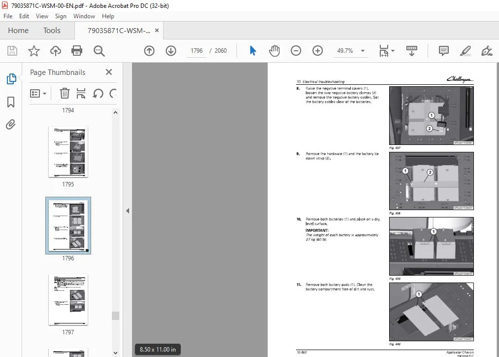
10 Electrical troubleshooting 10-1
10 1 General information 10-15
10 1 1 Introduction to the electrical system 10-15
10 1 2 Basic electrical troubleshooting procedures 10-15
10 1 3 Electrical service tools 10-15
10 1 4 Test a fuse 10-16
10 1 5 Test a diode 10-16
10 1 6 Test a relay 10-16
10 2 Failure mode indicator descriptions 10-18
10 2 1 Failure mode indicator ( F M I ) description 10- 18
10 3 00 Engine modul e 10-22
10 3 1 Code SA 00 S PN 17 6 1 F M I 0 1 10-2 2
Applicator Chassis
79035877C
10 3 1 1 D E F tank sensor electrical schematic 10-2 3
Code SA 00 S P N 1 76 1 F M I 03 1 0-2 5
1 0 3 2 1 D E F tank sensor electrical schematic 1 0-2 6
Code SA 00 S P N 3031 F M I 03 1 0-2 8
1 0 3 3 1 D E F tank sensor electrical schematic 1 0-2 9
Code SA 00 S P N 3031 F M I 04 1 0-31
1 0 3 4 1 D E F tank sensor electrical schematic 1 0-32
Code SA 00 SPN 3031 FMI 1 4 1 0-34
1 0 3 5 1 D E F tank sensor electrical schematic 1 0-35
Code SA 00 S P N 3031 F M I 1 6 1 0-37
1 0 3 6 1 D E F tank sensor electrical schematic 1 0-38
Code SA 00 S P N 336 3 F M I 03 1 0-40
1 0 3 7 1 D E F tank sensor electrical schematic 1 0-41
Code SA 00 S P N 336 3 F M I 04 1 0-43
1 0 3 8 1 D E F tank sensor electrical schematic 1 0-44
Code SA 00 S P N 336 3 F M I 05 1 0-46
1 0 3 9 1 D E F tank sensor electrical schematic 1 0-47
Code SA 00 S P N 336 3 F M I 31 1 0-49
1 0 3 1 0 1 D E F tank sensor electrical schematic 1 0-5 0
Code SA 00 S P N 4334 F M I 03 1 0-5 2
1 0 3 1 1 1 D E F tank sensor electrical schematic 1 0-5 3
Code SA 00 S P N 4334 F M I 04 1 0-5 5
1 0 3 1 2 1 D E F tank sensor electrical schematic 1 0-5 6
Code SA 00 S P N 4340 F M I 03 1 0-5 8
1 0 3 1 3 1 D E F tank sensor electrical schematic 1 0-5 9
Code SA 00 S P N 4340 F M I 04 1 0-6 1
1 0 3 1 4 1 D E F tank sensor electrical schematic 1 0-6 2
1 0 3 1 4 2 Diesel exhaust fluid power electrical schematic 1 0-6 4
Code SA 00 S P N 4340 F M I 05 1 0-6 5
1 0 3 1 5 1 D E F tank sensor electrical schematic 1 0-6 6
1 0 3 1 5 2 Diesel exhaust fluid power electrical schematic 1 0-6 8
Code SA 00 S P N 4340 F M I 31 1 0-6 9
1 0 3 1 6 1 Diesel exhaust fluid power electrical schematic 1 0-70
Code SA 00 S P N 4342 F M I 03 1 0-71
1 0 3 1 7 1 Diesel exhaust fluid power electrical schematic 1 0-72
Code SA 00 S P N 4342 F M I 04 1 0-73
1 0 3 1 8 1 Diesel exhaust fluid power electrical schematic 1 0-74
Code SA 00 S P N 4342 F M I 05 1 0-75
1 0 3 1 9 1 Diesel exhaust fluid power electrical schematic 1 0-76
Code SA 00 S P N 4342 F M I 31 1 0-77
1 0 3 2 0 1 Diesel exhaust fluid power electrical schematic 1 0-78
Code SA 00 S P N 4344 F M I 02 1 0-79
1 0 3 2 1 1 Diesel exhaust fluid power electrical schematic 1 0-80
Code SA 00 S P N 4344 F M I 03 1 0-81
1 0 3 2 2 1 Diesel exhaust fluid power electrical schematic 1 0-82
Code SA 00 S P N 4344 F M I 04 1 0-83
1 0 3 2 3 1 Diesel exhaust fluid power electrical schematic 1 0-84
Code SA 00 S P N 4344 F M I 08 1 0-85
1 0 3 2 4 1 Diesel exhaust fluid power electrical schematic 1 0-86
Code SA 00 S P N 4344 F M I 1 2 1 0-87
1 0 3 2 5 1 Diesel exhaust fluid power electrical schematic 1 0-88
Code SA 00 S P N 4344 F M I 31 1 0-89
1 0 3 2 6 1 Diesel exhaust fluid power electrical schematic 1 0-90
Code SA 00 S P N 4346 F M I 03 1 0-91
1 0 3 2 7 1 Diesel exhaust fluid power electrical schematic 1 0-92
Code SA 00 S P N 4346 F M I 04 1 0-93
1 0 3 2 8 1 Diesel exhaust fluid power electrical schematic 1 0-94
Code SA 00 S P N 4346 F M I 31 1 0-95
1 0 3 2 9 1 Diesel exhaust fluid power electrical schematic 1 0-96
Table of contents
Code SA 00 S P N 435 4 F M I 04 1 0-97
1 0 3 30 1 Diesel exhaust fluid power electrical schematic 1 0-98
Code SA 00 S P N 435 4 F M I 03 1 0-99
1 0 3 31 1 Diesel exhaust fluid power electrical schematic 1 0-1 00
Code SA 00 S P N 435 5 F M I 03 1 0-1 01
1 0 3 32 1 Diesel exhaust fluid power electrical schematic 1 0-1 02
Code SA 00 S P N 435 5 F M I 04 1 0-1 03
1 0 3 33 1 Diesel exhaust fluid power electrical schematic 1 0-1 04
Code SA 00 S P N 435 6 F M I 03 1 0-1 05
1 0 3 34 1 Diesel exhaust fluid power electrical schematic 1 0-1 06
Code SA 00 S P N 435 7 F M I 03 1 0-1 07
1 0 3 35 1 Diesel exhaust fluid power electrical schematic 1 0-1 08
Code SA 00 S P N 435 7 F M I 04 1 0-1 09
1 0 3 36 1 Diesel exhaust fluid power electrical schematic 1 0-1 1 0
Code SA 00 S P N 435 7 F M I 05 1 0-1 1 1
1 0 3 37 1 Diesel exhaust fluid power electrical schematic 1 0-1 1 2
Code SA 00 S P N 4376 F M I 03 1 0-1 1 3
1 0 3 38 1 Diesel exhaust fluid power electrical schematic 1 0-1 1 4
Code SA 00 S P N 4376 F M I 04 1 0-1 1 5
1 0 3 39 1 Diesel exhaust fluid power electrical schematic 1 0-1 1 6
Code SA 00 S P N 4376 F M I 05 1 0-1 1 7
1 0 3 40 1 Diesel exhaust fluid power electrical schematic 1 0-1 1 8
Code SA 00 S P N 4376 F M I 31 1 0-1 1 9
1 0 3 41 1 Diesel exhaust fluid power electrical schematic 1 0-1 2 0
Code SA 00 S P N 5 2 1 000 F M I 02 1 0-1 2 1
1 0 3 42 1 Diesel exhaust fluid power electrical schematic 1 0-1 2 2
Code SA 00 S P N 5 2 1 000 F M I 08 1 0-1 2 3
1 0 3 43 1 Diesel exhaust fluid power electrical schematic 1 0-1 2 4
Code SA 00 S P N 5 2 1 001 F M I 03 1 0-1 2 5
1 0 3 44 1 Diesel exhaust fluid power electrical schematic 1 0-1 2 6
Code SA 00 S P N 5 2 1 001 F M I 04 1 0-1 2 7
1 0 3 45 1 Diesel exhaust fluid power electrical schematic 1 0-1 2 8
Code SA 00 S P N 5 2 1 001 F M I 31 1 0-1 2 9
1 0 3 46 1 Diesel exhaust fluid power electrical schematic 1 0-1 30
Code SA 00 S P N 5 2 1 002 F M I 03 1 0-1 31
1 0 3 47 1 Diesel exhaust fluid power electrical schematic 1 0-1 32
Code SA 00 S P N 5 2 1 002 F M I 04 1 0-1 33
1 0 3 48 1 Diesel exhaust fluid power electrical schematic 1 0-1 34
Code SA 00 S P N 5 2 1 002 F M I 05 1 0-1 35
1 0 3 49 1 Diesel exhaust fluid power electrical schematic 1 0-1 36
Code SA 00 S P N 5 2 1 002 F M I 31 1 0-1 37
1 0 3 5 0 1 Diesel exhaust fluid power electrical schematic 1 0-1 38
Code SA 00 S P N 5 2 1 003 F M I 03 1 0-1 39
1 0 3 5 1 1 Diesel exhaust fluid power electrical schematic 1 0-1 40
Code SA 00 S P N 5 2 1 003 F M I 04 1 0-1 41
1 0 3 5 2 1 Diesel exhaust fluid power electrical schematic 1 0-1 42
Code SA 00 S P N 5 2 1 004 F M I 02 1 0-1 43
1 0 3 5 3 1 Diesel exhaust fluid N O X sensor electrical schematic 1 0-1 44
Code SA 00 S P N 5 2 1 004 F M I 1 1 1 0-1 45
1 0 3 5 4 1 Diesel exhaust fluid N OX sensor electrical schematic 1 0-1 46
Code SA 00 S P N 5 2 1 004 F M I 1 2 1 0-1 47
1 0 3 5 5 1 Diesel exhaust fluid N OX sensor electrical schematic 1 0-1 48
Code SA 00 S P N 5 2 1 005 F M I 02 1 0-1 49
1 0 3 5 6 1 Diesel exhaust fluid N OX sensor electrical schematic 1 0-1 5 0
Code SA 00 S P N 5 2 1 005 F M I 1 1 1 0-1 5 1
1 0 3 5 7 1 Diesel exhaust fluid N O X sensor electrical schematic 1 0-1 5 2
Code SA 00 S P N 5 2 1 005 F M I 1 2 1 0-1 5 3
1 0 3 5 8 1 Diesel exhaust fluid N OX sensor electrical schematic 1 0-1 5 4
Table of contents
10 3 59 Code SA 00 S PN 5 2 1006 F MI 12 10-15 5
10 3 59 1 Diesel exhaust fluid NOX sensor electrical schematic 10-15 6
10 3 6 0 Code SA 00 S PN 5 2 1007 F MI 10 10-157
10 3 6 0 1 D E F tank sensor electrical schematic 10-158
10 3 6 1 Code SA 00 S PN 5 2 1007 F MI 31 10-16 0
10 3 6 1 1 D E F tank sensor electrical schematic 10-16 1
10 3 6 2 Code SA 00 S PN 5 2 1008 F MI 00 10-16 3
10 3 6 2 1 D E F tank sensor electrical schematic 10-16 4
10 3 6 3 Code SA 00 S PN 5 2 1008 F MI 0 1 10-16 6
10 3 6 3 1 D E F tank sensor electrical schematic 10-167
10 3 6 4 Code SA 00 S PN 5 2 1007 F MI 14 10-16 9
10 3 6 4 1 D E F tank sensor electrical schematic 10- 17 0
10 4 03 Transmission module 10-172
10 4 1 Code SA 0 3 S P N 35 09 F M I 0 1 10- 17 2
10 4 2 Code SA 0 3 S P N 5 2 2 16 6 F MI 0 5 10- 17 3
10 4 2 1 Wheel leg electrical circuits 10- 17 5
10 4 2 2 Wheel leg bulkhead electrical circuits 10- 177
10 4 3 Code SA 0 3 S P N 5 2 2 16 6 F MI 06 10-178
10 4 3 1 Wheel leg electrical circuits 10-18 0
10 4 3 2 Wheel leg bulkhead electrical circuits 10- 18 2
10 4 4 Code SA 0 3 S P N 5 2 2 167 F MI 0 5 10- 18 3
10 4 4 1 Wheel leg electrical circuits 10-18 5
10 4 4 2 Wheel leg bulkhead electrical circuits 10- 187
10 4 5 Code SA 0 3 S P N 5 2 2 167 F MI 06 10- 188
10 4 5 1 Wheel leg electrical circuits 10-19 0
10 4 5 2 Wheel leg bulkhead electrical circuits 10-19 2
10 4 6 Code SA 0 3 S P N 5 2 2 168 F MI 0 5 10-19 3
10 4 6 1 Wheel leg electrical circuits 10-19 5
10 4 6 2 Wheel leg bulkhead electrical circuits 10-197
10 4 7 Code SA 0 3 S P N 5 2 2 168 F MI 06 10-19 8
10 4 7 1 Wheel leg electrical circuits 10-2 00
10 4 7 2 Wheel leg bulkhead electrical circuits 10-2 0 2
10 4 8 Code SA 0 3 S P N 5 2 2 16 9 F MI 05 10-2 0 3
10 4 8 1 Wheel leg electrical circuits 10-2 0 5
10 4 8 2 Wheel leg bulkhead electrical circuits 10-2 07
10 4 9 Code SA 0 3 S P N 5 2 2 16 9 F MI 06 10-2 08
10 4 9 1 Wheel leg electrical circuits 10-2 10
10 4 9 2 Wheel leg bulkhead electrical circuits 10-2 1 2
10 5 05 Armrest module 10-214
10 5 1 Code SA 05 S P N 158 F M I 00 10-2 14
10 5 1 1 Controller power electrical circuits 10-2 15
10 5 2 Code SA 0 5 S P N 158 F M I 0 1 10-2 16
10 5 2 1 Controller power electrical circuits 10-2 17
10 5 3 Code SA 05 S P N 18 6 5 F MI 0 2 10-2 18
10 5 3 1 Key switch harness layout 10-2 19
10 5 3 2 Key switch electrical circuits 10-2 2 1
10 5 4 Code SA 0 5 S P N 2 347 F MI 0 2 10-2 2 2
10 5 4 1 Lights and turn signal switch harness layout 10-2 2 4
10 5 4 2 Steering column switch electrical circuits 10-2 2 5
10 5 5 Code SA 0 5 S P N 2 34 9 F MI 0 2 10-2 2 6
10 5 5 1 Lights and turn signal switch harness layout 10-2 27
10 5 5 2 Steering column switch electrical circuits 10-2 2 8
10 5 6 Code SA 0 5 S P N 2 367 F MI 0 2 10-2 2 9
10 5 6 1 Lights and turn signal switch harness layout 10-2 30
10 5 6 2 Steering column switch electrical circuits 10-2 31
10 5 7 Code SA 05 S P N 2 36 9 F MI 0 2 10-2 32
10 5 7 1 Lights and turn signal switch harness layout 10-2 33
10 5 7 2 Steering column switch electrical circuits 10-2 34
Table of contents
Code SA 05 S P N 2 403 F M I 02 1 0-2 35
1 0 5 8 1 Lights and turn signal s witch harness layout 1 0-2 36
1 0 5 8 2 Steering column s witch electrical circuits 1 0-2 37
Code SA 05 S P N 2 82 5 F M I 02 1 0-2 38
1 0 5 9 1 Reverse s witch layout 1 0-2 39
1 0 5 9 2 Reverse s witch electrical circuits 1 0-2 40
Code SA 05 S P N 2 82 5 F M I 04 1 0-2 40
1 0 5 1 0 1 Reverse s witch layout 1 0-2 42
1 0 5 1 0 2 Reverse s witch electrical circuits 1 0-2 42
Code SA 05 S P N 2 833 F M I 31 1 0-2 43
Code SA 05 SPN 2 85 8 F MI 02 1 0-2 43
Code SA 05 S P N 35 09 F M I 03 1 0-2 43
1 0 5 1 3 1 5 volt electrical circuits 1 0-2 45
Code SA 05 S P N 35 09 F M I 04 1 0-2 45
1 0 5 1 4 1 5 volt electrical circuits 1 0-2 47
Code SA 05 S P N 35 1 1 F M I 03 1 0-2 47
1 0 5 1 5 1 5 volt electrical circuits 1 0-2 49
Code SA 05 S P N 35 1 1 F M I 04 1 0-2 49
1 0 5 1 6 1 5 volt electrical circuits 1 0-2 5 1
Code SA 05 S P N 36 46 F M I 03 1 0-2 5 1
1 0 5 1 7 1 Park brake and neutral s witch electrical circuits 1 0-2 5 5
1 0 5 1 7 2 Park brake and service brake s witches electrical circuits 1 0-2 5 7
Code SA 05 S P N 36 46 F M I 04 1 0-2 5 8
1 0 5 1 8 1 Park brake and neutral s witch electrical circuits 1 0-2 6 2
1 0 5 1 8 2 Park brake and service brake s witches electrical circuits 1 0-2 6 4
Code SA 05 S P N 36 5 2 F M I 00 1 0-2 6 5
1 0 5 1 9 1 Spray handle connector location 1 0-2 6 7
1 0 5 1 9 2 Spray handle connector electrical circuits 1 0-2 6 8
Code SA 05 S P N 36 5 2 F M I 01 1 0-2 6 9
1 0 5 2 0 1 Spray handle connector location 1 0-2 71
1 0 5 2 0 2 Spray handle connector electrical circuits 1 0-2 72
Code SA 05 S P N 36 5 2 F M I 03 1 0-2 73
1 0 5 2 1 1 Spray handle connector location 1 0-2 75
1 0 5 2 1 2 Spray handle connector electrical circuits 1 0-2 76
Code SA 05 S P N 36 5 2 F M I 04 1 0-2 77
1 0 5 2 2 1 Spray handle connector location 1 0-2 79
1 0 5 2 2 2 Spray handle connector electrical circuits 1 0-2 80
Code SA 05 SPN 36 5 3 F MI 00 1 0-2 81
1 0 5 2 3 1 Spray handle connector location 1 0-2 83
1 0 5 2 3 2 Spray handle connector electrical circuits 1 0-2 84
Code SA 05 SPN 36 5 3 F MI 01 1 0-2 85
1 0 5 2 4 1 Spray handle connector location 1 0-2 87
1 0 5 2 4 2 Spray handle connector electrical circuits 1 0-2 88
Code SA 05 SPN 36 5 3 F MI 03 1 0-2 89
1 0 5 2 5 1 Spray handle connector location 1 0-2 91
1 0 5 2 5 2 Spray handle connector electrical circuits 1 0-2 92
Code SA 05 SPN 36 5 3 F MI 04 1 0-2 93
1 0 5 2 6 1 Spray handle connector location 1 0-2 95
1 0 5 2 6 2 Spray handle connector electrical circuits 1 0-2 96
Code SA 05 S P N 5 2 01 93 F M I 00 1 0-2 97
1 0 5 2 7 1 Liquid system s witches electrical circuit 1 0-2 99
Code SA 05 S P N 5 2 01 93 F M I 01 1 0-300
1 0 5 2 8 1 Liquid system s witches electrical circuit 1 0-302
Code SA 05 S P N 5 2 01 93 F M I 03 1 0-303
1 0 5 2 9 1 Liquid system s witches electrical circuit 1 0-305
Code SA 05 S P N 5 2 01 93 F M I 04 1 0-306
1 0 5 30 1 Liquid system s witches electrical circuit 1 0-308
Code SA 05 SPN 5 2 2 06 3F MI 00 1 0-309
Table of contents
1 0 5 32
1 0 5 33
1 0 5 34
1 0 5 35
1 0 5 36
1 0 5 37
1 0 5 38
1 0 5 39
1 0 5 40
1 0 5 41
1 0 5 42
1 0 5 43
1 0 5 44
1 0 5 45
1 0 5 46
1 0 5 47
1 0 5 48
1 0 5 49
1 0 5 5 0
1 0 5 31 1 Spray handle connector location 1 0-31 1
1 0 5 31 2 Spray handle connector electrical circuits 1 0-31 2
Code SA 05 SPN 5 2 2 06 3F MI 01 1 0-31 3
1 0 5 32 1 Spray handle connector location 1 0-31 5
1 0 5 32 2 Spray handle connector electrical circuits 1 0-31 6
Code SA 05 SPN 5 2 2 06 3F MI 03 1 0-31 7
1 0 5 33 1 Spray handle connector location 1 0-31 9
1 0 5 33 2 Spray handle connector electrical circuits 1 0-32 0
Code SA 05 SPN 5 2 2 06 3F MI 04 1 0-32 1
1 0 5 34 1 Spray handle connector location 1 0-32 3
1 0 5 34 2 Spray handle connector electrical circuits 1 0-32 4
Code SA 05 SPN 5 2 2 06 4F MI 00 1 0-32 5
1 0 5 35 1 Spray handle connector location 1 0-32 7
1 0 5 35 2 Spray handle connector electrical circuits 1 0-32 8
Code SA 05 SPN 5 2 2 06 4F MI 01 1 0-32 9
1 0 5 36 1 Spray handle connector location 1 0-331
1 0 5 36 2 Spray handle connector electrical circuits 1 0-332
Code SA 05 SPN 5 2 2 06 4F MI 03 1 0-333
1 0 5 37 1 Spray handle connector location 1 0-335
1 0 5 37 2 Spray handle connector electrical circuits 1 0-336
Code SA 05 SPN 5 2 2 06 4F MI 04 1 0-337
1 0 5 38 1 Spray handle connector location 1 0-339
1 0 5 38 2 Spray handle connector electrical circuits 1 0-340
Code SA 05 S P N 5 2 2 06 5 F M I 00 1 0-341
1 0 5 39 1 Spray handle connector location 1 0-343
1 0 5 39 2 Spray handle connector electrical circuits 1 0-344
Code SA 05 S P N 5 2 2 06 5 F M I 01 1 0-345
1 0 5 40 1 Spray handle connector location 1 0-347
1 0 5 40 2 Spray handle connector electrical circuits 1 0-348
Code SA 05 S P N 5 2 2 06 5 F M I 03 1 0-349
1 0 5 41 1 Spray handle connector location 1 0-35 1
1 0 5 41 2 Spray handle connector electrical circuits 1 0-35 2
Code SA 05 S P N 5 2 2 06 5 F M I 04 1 0-35 3
1 0 5 42 1 Spray handle connector location 1 0-355
1 0 5 42 2 Spray handle connector electrical circuits 1 0-35 6
Code SA 05 S P N 5 2 2 06 6 F M I 00 1 0-35 7
1 0 5 43 1 Spray handle connector location 1 0-35 9
1 0 5 43 2 Spray handle connector electrical circuits 1 0-36 0
Code SA 05 S P N 5 2 2 06 6 F M I 01 1 0-36 1
1 0 5 44 1 Spray handle connector location 1 0-36 3
1 0 5 44 2 Spray handle connector electrical circuits 1 0-36 4
Code SA 05 S P N 5 2 2 06 6 F M I 03 1 0-36 5
1 0 5 45 1 Spray handle connector location 1 0-36 7
1 0 5 45 2 Spray handle connector electrical circuits 1 0-36 8
Code SA 05 S P N 5 2 2 06 6 F M I 04 1 0-36 9
1 0 5 46 1 Spray handle connector location 1 0-371
1 0 5 46 2 Spray handle connector electrical circuits 1 0-372
Code SA 05 SPN 5 2 2 06 7F MI 00 1 0-373
1 0 5 47 1 Spray handle connector location 1 0-375
1 0 5 47 2 Spray handle connector electrical circuits 1 0-376
Code SA 05 SPN 5 2 2 06 7F MI 01 1 0-377
1 0 5 48 1 Spray handle connector location 1 0-379
1 0 5 48 2 Spray handle connector electrical circuits 1 0-380
Code SA 05 SPN 5 2 2 06 7F MI 03 1 0-381
1 0 5 49 1 Spray handle connector location 1 0-383
1 0 5 49 2 Spray handle connector electrical circuits 1 0-384
Code SA 05 SPN 5 2 2 06 7F MI 04 1 0-385
1 0 5 5 0 1 Spray handle connector location 1 0-387
Applicator Chassis
79035871C
Applicator Chassis
79035877C
Table of contents
10 5 5 0 2 Spray handle connector electrical circuits 10- 388
Code SA 05 S P N 5 2 2 06 8 F MI 00 10- 389
10 5 5 1 1 Spray handle connector location 10-39 1
10 5 5 1 2 Spray handle connector electrical circuits 10-39 2
Code SA 05 S P N 5 2 2 06 8 F MI 0 1 10-39 3
10 5 5 2 1 Spray handle connector location 10-39 5
10 5 5 2 2 Spray handle connector electrical circuits 10-39 6
Code SA 05 S P N 5 2 2 06 8 F MI 0 3 10-397
10 5 5 3 1 Spray handle connector location 10-39 9
10 5 5 3 2 Spray handle connector electrical circuits 10-4 00
Code SA 0 5 S P N 5 2 2 06 8 F MI 04 10-4 0 1
10 5 54 1 Spray handle connector location 10-4 0 3
10 5 54 2 Spray handle connector electrical circuits 10-4 04
Code SA 05 S P N 5 2 2 06 9 F MI 00 10-4 0 5
10 5 5 5 1 Spray handle connector location 10-4 07
10 5 5 5 2 Spray handle connector electrical circuits 10-4 08
Code SA 0 5 S P N 5 2 2 06 9 F MI 0 1 10-4 09
10 5 5 6 1 Spray handle connector location 10-4 1 1
10 5 5 6 2 Spray handle connector electrical circuits 10-4 1 2
Code SA 0 5 S P N 5 2 2 06 9 F MI 0 3 10-4 1 3
10 5 57 1 Spray handle connector location 10-4 15
10 5 57 2 Spray handle connector electrical circuits 10-4 16
Code SA 0 5 S P N 5 2 2 06 9 F MI 04 10-4 17
10 5 58 1 Spray handle connector location 10-4 19
10 5 58 2 Spray handle connector electrical circuits 10-4 2 0
Code SA 0 5 S P N 5 2 2 07 0 F MI 00 10-4 2 1
10 5 59 1 Spray handle connector location 10-4 2 3
10 5 59 2 Spray handle connector electrical circuits 10-4 2 4
Code S A 0 5 S P N 5 2 2 07 0 F MI 0 1 10-4 2 5
10 5 6 0 1 Spray handle connector location 10-4 27
10 5 6 0 2 Spray handle connector electrical circuits 10-4 2 8
Code SA 0 5 S P N 5 2 2 07 0 F MI 0 3 10-4 2 9
10 5 6 1 1 Spray handle connector location 10-4 31
10 5 6 1 2 Spray handle connector electrical circuits 10-4 32
Code SA 05 S P N 5 2 2 07 0 F MI 04 10-4 33
10 5 6 2 1 Spray handle connector location 10-4 35
10 5 6 2 2 Spray handle connector electrical circuits 10-4 36
Code SA 0 5 S P N 5 2 2 07 1 F MI 00 10-4 37
10 5 6 3 1 Spray handle connector location 10-4 39
10 5 6 3 2 Spray handle connector electrical circuits 10-4 4 0
Code S A 0 5 S P N 5 2 2 07 1 F MI 0 1 10-4 4 1
10 5 6 4 1 Spray handle connector location 10-4 4 3
10 5 6 4 2 Spray handle connector electrical circuits 10-4 4 4
Code S A 0 5 S P N 5 2 2 07 1 F MI 0 3 10-4 4 5
10 5 6 5 1 Spray handle connector location 10-4 47
10 5 6 5 2 Spray handle connector electrical circuits 10-4 48
Code SA 0 5 S P N 5 2 2 07 1 F MI 04 10-4 4 9
10 5 6 6 1 Spray handle connector location 10-4 5 1
10 5 6 6 2 Spray handle connector electrical circuits 10-4 5 2
Code SA 0 5 S P N 5 2 2 07 2 F MI 0 0 10-4 5 3
10 5 6 7 1 Spray handle connector location 10-4 5 5
10 5 6 7 2 Spray handle connector electrical circuits 10-4 5 6
Code S A 0 5 S P N 5 2 2 07 2 F MI 0 1 10-4 57
10 5 6 8 1 Spray handle connector location 10-4 59
10 5 6 8 2 Spray handle connector electrical circuits 10-4 6 0
Code SA 0 5 S P N 5 2 2 07 2 F MI 0 3 10-4 6 1
10 5 6 9 1 Spray handle connector location 10-4 6 3
10 5 6 9 2 Spray handle connector electrical circuits 10-4 6 4
Code SA 05 S P N 5 2 2 072 F M I 04 1 0-46 5
1 0 5 70 1 Spray handle connector location 1 0-46 7
1 0 5 70 2 Spray handle connector electrical circuits 1 0-46 8
Code SA 05 S P N 5 2 2 073 F M I 00 1 0-46 9
1 0 5 71 1 Spray handle connector location 1 0-471
1 0 5 71 2 Spray handle connector electrical circuits 1 0-472
Code SA 05 S P N 5 2 2 073 F M I 01 1 0-47 3
1 0 5 72 1 Spray handle connector location 1 0-475
1 0 5 72 2 Spray handle connector electrical circuits 1 0-476
Code SA 05 S P N 5 2 2 073 F M I 03 1 0-477
1 0 5 73 1 Spray handle connector location 1 0-479
1 0 5 73 2 Spray handle connector electrical circuits 1 0-480
Code SA 05 S P N 5 2 2 073 F M I 04 1 0-481
1 0 5 74 1 Spray handle connector location 1 0-483
1 0 5 74 2 Spray handle connector electrical circuits 1 0-484
Code SA 05 S P N 5 2 2 073 F M I 05 1 0-485
1 0 5 75 1 Spray handle connector location 1 0-487
1 0 5 75 2 Spray handle connector electrical circuits 1 0-488
Code SA 05 S P N 5 2 2 073 F M I 06 1 0-489
1 0 5 76 1 Spray handle connector location 1 0-491
1 0 5 76 2 Spray handle connector electrical circuits 1 0-492
Code SA 05 S P N 5 2 2 075 F M I 00 1 0-493
1 0 5 77 1 Spray handle connector location 1 0-495
1 0 5 77 2 Spray handle connector electrical circuits 1 0-496
Code SA 05 S P N 5 2 2 075 F M I 01 1 0-497
1 0 5 78 1 Spray handle connector location 1 0-499
1 0 5 78 2 Spray handle connector electrical circuits 1 0-5 00
Code SA 05 S P N 5 2 2 075 F M I 03 1 0-5 01
1 0 5 79 1 Spray handle connector location 1 0-5 03
1 0 5 79 2 Spray handle connector electrical circuits 1 0-5 04
Code SA 05 S P N 5 2 2 075 F M I 04 1 0-5 05
1 0 5 80 1 Spray handle connector location 1 0-5 07
1 0 5 80 2 Spray handle connector electrical circuits 1 0-5 08
Code SA 05 S P N 5 2 2 076 F M I 05 1 0-5 09
1 0 5 81 1 Spray handle connector location 1 0-5 1 1
1 0 5 81 2 Spray handle connector electrical circuits 1 0-5 1 2
Code SA 05 S P N 5 2 2 076 F M I 06 1 0-5 1 3
1 0 5 82 1 Spray handle connector location 1 0-5 1 5
1 0 5 82 2 Spray handle connector electrical circuits 1 0-5 1 6
Code SA 05 S P N 5 2 2 077 F M I 00 1 0-5 1 7
1 0 5 83 1 Spray handle connector location 1 0-5 1 9
1 0 5 83 2 Spray handle connector electrical circuits 1 0-5 2 0
Code SA 05 S P N 5 2 2 077 F M I 01 1 0-5 2 1
1 0 5 84 1 Spray handle connector location 1 0-5 2 3
1 0 5 84 2 Spray handle connector electrical circuits 1 0-5 2 4
Code SA 05 S P N 5 2 2 077 F M I 03 1 0-5 2 5
1 0 5 85 1 Spray handle connector location 1 0-5 2 7
1 0 5 85 2 Spray handle connector electrical circuits 1 0-5 2 8
Code SA 05 S P N 5 2 2 077 F M I 04 1 0-5 2 9
1 0 5 86 1 Spray handle connector location 1 0-5 31
1 0 5 86 2 Spray handle connector electrical circuits 1 0-5 32
Code SA 05 S P N 5 2 2 078 F M I 00 1 0-5 33
1 0 5 87 1 Spray handle connector location 1 0-5 35
1 0 5 87 2 Spray handle connector electrical circuits 1 0-5 36
Code SA 05 S P N 5 2 2 078 F M I 01 1 0-5 37
1 0 5 88 1 Spray handle connector location 1 0-5 39
1 0 5 88 2 Spray handle connector electrical circuits 1 0-5 40
Code SA 05 S P N 5 2 2 078 F M I 03 1 0-5 41
Applicator Chassis
79035871C
Table of contents
10 5 8 9 1 Spray handle connector location 10-5 4 3
10 5 8 9 2 Spray handle connector electrical circuits 10-5 4 4
10 5 90 Code SA 0 5 S P N 5 220 7 8 F MI 0 4 10-5 4 5
10 5 90 1 Spray handle connector location 10-5 4 7
10 5 90 2 Spray handle connector electrical circuits 10-5 4 8
10 5 9 1 Code SA 0 5 S P N 5 220 7 9 F MI 00 10-5 4 9
10 5 9 1 1 End row switches electrical circuits 10-5 5 1
10 5 9 2 Code SA 0 5 S P N 5 220 7 9 F MI 0 1 10-5 5 2
10 5 9 2 1 End row switches electrical circuits 10-5 5 4
10 5 9 3 Code SA 0 5 S P N 5 220 7 9 F MI 0 3 10-5 5 5
10 5 9 3 1 End row switches electrical circuits 10-5 5 7
10 5 9 4 Code SA 0 5 S P N 5 220 7 9 F MI 0 4 10-5 5 8
10 5 9 4 1 End row switches electrical circuits 10-5 60
10 5 9 5 Code SA 0 5 S P N 5 220 80 F MI 00 10-5 6 1
10 5 9 5 1 End row switches electrical circuits 10-5 6 3
10 5 9 6 Code SA 0 5 S P N 5 220 80 F MI 01 10-5 6 4
10 5 9 6 1 End row switches electrical circuits 10-5 6 6
10 5 9 7 Code SA 0 5 S P N 5 220 80 F MI 0 3 10-5 6 7
10 5 97 1 End row switches electrical circuits 10-5 6 9
10 5 9 8 Code SA 0 5 S P N 5 220 80 F MI 0 4 10-5 70
10 5 9 8 1 End row switches electrical circuits 10-5 7 2
10 5 9 9 Code SA 0 5 S P N 5 220 8 3 F MI 00 10-5 7 3
10 5 9 9 1 Boom switches electrical circuits 10-5 7 5
10 5 100 Code SA 0 5 S P N 5 220 8 3 F MI 01 10-5 7 6
10 5 100 1 Boom switches electrical circuits 10-5 7 8
10 5 101 Code SA 0 5 S P N 5 220 8 3 F MI 0 3 10-5 7 9
10 5 101 1 Boom switches electrical circuits 10-5 8 1
10 5 10 2 Code SA 0 5 S P N 5 220 8 3 F MI 0 4 10-5 8 2
10 5 10 2 1 Boom switches electrical circuits 10-5 8 4
10 5 10 3 Code SA 0 5 S P N 5 220 8 4 F MI 00 10-5 8 5
10 5 10 3 1 Boom switches electrical circuits 10-5 8 7
10 5 10 4 Code SA 0 5 S P N 5 220 8 4 F MI 01 10-5 8 8
10 5 10 4 1 Boom switches electrical circuits 10-5 90
10 5 10 5 Code SA 0 5 S P N 5 220 8 4 F MI 0 3 10-5 9 1
10 5 10 5 1 Boom switches electrical circuits 10-5 9 3
10 5 10 6 Code SA 0 5 S P N 5 220 8 4 F MI 0 4 10-5 9 4
10 5 10 6 1 Boom switches electrical circuits 10-5 9 6
10 5 10 7 Code SA 0 5 S P N 5 220 8 6 F MI 00 10-5 9 7
10 5 107 1 Liquid system switches electrical circuit 10-5 9 9
10 5 10 8 Code SA 0 5 S P N 5 220 8 6 F MI 01 10-600
10 5 10 8 1 Liquid system switches electrical circuit 10-60 2
10 5 10 9 Code SA 0 5 S P N 5 220 8 6 F MI 0 3 10-60 3
10 5 10 9 1 Liquid system switches electrical circuit 10-60 5
10 5 1 10 Code SA 0 5 S P N 5 220 8 6 F MI 0 4 10-60 6
10 5 1 10 1 Liquid system switches electrical circuit 10-60 8
10 5 1 1 1 Code SA 0 5 S P N 5 220 8 8 F MI 00 10-60 9
10 5 1 1 1 1 Spray handle connector electrical circuits 10-6 1 1
10 5 1 1 2 Code SA 0 5 S P N 5 220 8 8 F MI 01 10-6 1 2
10 5 1 1 2 1 Spray handle connector electrical circuits 10-6 1 4
10 5 1 1 3 Code SA 0 5 S P N 5 220 8 8 F MI 0 3 10-6 1 5
10 5 1 1 3 1 Spray handle connector electrical circuits 10-6 1 7
10 5 1 1 4 Code SA 0 5 S P N 5 220 8 8 F MI 0 4 10-6 1 8
10 5 1 1 4 1 Spray handle connector electrical circuits 10-6 20
10 5 1 1 5 Code SA 0 5 S P N 5 220 8 9 F MI 0 5 10-6 21
10 5 1 1 5 1 Auxilliary output electrical circuits 10-6 23
10 5 1 1 6 Code SA 0 5 S P N 5 220 8 9 F MI 0 6 10-6 24
10 5 1 1 6 1 Auxilliary output electrical circuits 10-6 26
10 5 1 1 7 Code SA 0 5 S P N 5 220 90 F MI 0 5 10-6 27
Applicator Chassis
79035877C
Table of contents
1 0 5 1 1 7 1 Auxilliary output electrical circuits 1 0-6 2 9
1 0 5 1 1 8 Code SA 05 S P N 5 2 2 090 F M I 06 1 0-6 30
1 0 5 1 1 8 1 Auxilliary output electrical circuits 1 0-6 32
1 0 5 1 1 9 Code SA 05 S P N 5 2 2 094 F M I 05 1 0-6 33
1 0 5 1 1 9 1 Track adjust coil electrical circuits 1 0-6 35
1 0 5 1 2 0 Code SA 05 S P N 5 2 2 094 F M I 06 1 0-6 36
1 0 5 1 2 0 1 Track adjust coil electrical circuits 1 0-6 38
1 0 5 1 2 1 Code SA 05 S P N 5 2 2 095 F M I 05 1 0-6 39
1 0 5 1 2 1 1 Track adjust coil electrical circuits 1 0-6 42
1 0 5 1 2 2 Code SA 05 S P N 5 2 2 095 F M I 06 1 0-6 43
1 0 5 1 2 2 1 Track adjust coil electrical circuits 1 0-6 45
1 0 5 1 2 3 Code SA 05 S P N 5 2 2 096 F M I 05 1 0-6 46
1 0 5 1 2 3 1 Track adjust coil electrical circuits 1 0-6 49
1 0 5 1 2 4 Code SA 05 S P N 5 2 2 096 F M I 06 1 0-6 5 0
1 0 5 1 2 4 1 Track adjust coil electrical circuits 1 0-6 5 2
1 0 5 1 2 5 Code SA 05 S P N 5 2 2 097 F M I 05 1 0-6 5 3
1 0 5 1 2 5 1 Track adjust coil electrical circuits 1 0-6 5 6
1 0 5 1 2 6 Code SA 05 S P N 5 2 2 097 F M I 06 1 0-6 5 7
1 0 5 1 2 6 1 Track adjust coil electrical circuits 1 0-6 5 9
1 0 5 1 2 7 Code SA 05 S P N 5 2 2 098 F M I 05 1 0-6 6 0
1 0 5 1 2 7 1 Track adjust coil electrical circuits 1 0-6 6 3
1 0 5 1 2 8 Code SA 05 S P N 5 2 2 098 F M I 06 1 0-6 6 4
1 0 5 1 2 8 1 Track adjust coil electrical circuits 1 0-6 6 6
1 0 5 1 2 9 Code SA 05 S P N 5 2 2 099 F M I 05 1 0-6 6 7
1 0 5 1 2 9 1 Track adjust coil electrical circuits 1 0-6 70
1 0 5 1 30 Code SA 05 S P N 5 2 2 099 F M I 06 1 0-6 71
1 0 5 1 30 1 Track adjust coil electrical circuits 1 0-6 73
1 0 5 1 31 Code SA 05 S P N 5 2 2 1 00 F M I 05 1 0-6 74
1 0 5 1 31 1 Track adjust coil electrical circuits 1 0-6 77
1 0 5 1 32 Code SA 05 S P N 5 2 2 1 00 F M I 06 1 0-6 78
1 0 5 1 32 1 Track adjust coil electrical circuits 1 0-6 80
1 0 5 1 33 Code SA 05 S P N 5 2 2 1 01 F M I 05 1 0-6 81
1 0 5 1 33 1 Track adjust coil electrical circuits 1 0-6 84
1 0 5 1 34 Code SA 05 S P N 5 2 2 1 01 F M I 06 1 0-6 85
1 0 5 1 34 1 Track adjust coil electrical circuits 1 0-6 87
1 0 5 1 35 Code SA 05 S P N 5 2 2 1 04 F M I 05 1 0-6 88
1 0 5 1 35 1 Pro jection lamp and dome lamp electrical circuits 1 0-6 91
1 0 5 1 36 Code SA 05 S P N 5 2 2 1 04 F M I 06 1 0-6 92
1 0 5 1 36 1 Pro jection lamp and dome lamp electrical circuits 1 0-6 94
1 0 5 1 37 Code SA 05 S P N 5 2 2 1 5 1 F M I 00 1 0-6 95
1 0 5 1 37 1 Oiler and throttle s witch electrical circuits 1 0-6 96
1 0 5 1 38 Code SA 05 S P N 5 2 2 1 5 1 F M I 01 1 0-6 97
1 0 5 1 38 1 Oiler and throttle s witch electrical circuits 1 0-6 98
1 0 5 1 39 Code SA 05 S P N 5 2 2 1 5 1 F M I 03 1 0-6 99
1 0 5 1 39 1 Oiler and throttle s witch electrical circuits 1 0-700
1 0 5 1 40 Code SA 05 S P N 5 2 2 1 5 1 F M I 04 1 0-701
1 0 5 1 40 1 Oiler and throttle s witch electrical circuits 1 0-702
1 0 5 1 41 Code SA 05 SPN 5 2 2 1 5 5 FMI 1 4 1 0-703
1 0 5 1 42 Code SA 05 SPN 5 2 2 1 5 6 FMI 1 4 1 0-703
1 0 5 1 43 Code SA 05 SPN 5 2 2 1 5 8 F MI 31 1 0-703
1 0 5 1 44 Code SA 05 SPN 5 2 2 1 5 9 F MI 31 1 0-703
1 0 5 1 45 Code SA 05 SPN 5 2 2 1 6 0F MI 31 1 0-703
1 0 5 1 46 Code SA 05 S P N 5 2 2 1 6 1 F M I 03 1 0-704
1 0 5 1 46 1 Seat electrical circuits 1 0-705
1 0 5 1 47 Code SA 05 S P N 5 2 2 1 6 1 F M I 04 1 0-706
1 0 5 1 47 1 Seat electrical circuits 1 0-707
1 0 5 1 48 Code SA 05 SPN 5 2 2 1 74 FMI 1 3 1 0-708
1 0 5 1 49 Code SA 05 S P N 5 2 2 1 75 F M I 31 1 0-709
Applicator Chassis
79035871C
Table of contents
10 5 15 0 Code SA 05 S P N 5 2 2 177 F M I 14 10-7 09
10 5 15 1 Code SA 05 S P N 8 9 8 F M I 00 10-7 09
10 5 15 1 1 Throttle switch connector location 10-7 1 1
10 5 15 1 2 Oiler and throttle switch electrical circuits 10-7 1 2
10 5 15 2 Code SA 0 5 S P N 8 9 8 F M I 0 1 10-7 1 3
10 5 15 2 1 Throttle switch connector location 10-7 15
10 5 15 2 2 Oiler and throttle switch electrical circuits 10-7 16
10 5 15 3 Code SA 0 5 S P N 8 9 8 F M I 0 3 10-7 17
10 5 15 3 1 Throttle switch connector location 10-7 19
10 5 15 3 2 Oiler and throttle switch electrical circuits 10-7 19
10 5 15 4 Code SA 05 S P N 8 9 8 F M I 04 10-7 2 0
10 5 154 1 Throttle switch connector location 10-7 2 3
10 5 154 2 Oiler and throttle switch electrical circuits 10-7 2 3
1 0 6 56 Fou r wheel steer m o d u l e 10-725
10 6 1 Code SA 56 S P N 5 2 2 14 6 F MI 0 3 10-7 2 5
10 6 1 1 Four wheel steer activation relay electrical schematic 10-7 2 6
10 6 1 2 Wheel angle sensors electrical circuits 10-7 28
10 6 2 Code SA 5 6 S P N 5 2 2 14 6 F MI 04 10-7 2 9
10 6 2 1 Wheel angle sensors electrical circuits 10-7 31
10 6 2 2 Four wheel steer activation relay electrical schematic 10-7 33
10 6 3 Code SA 56 S P N 5 2 2 14 6 F MI 1 3 10-7 34
10 6 3 1 Wheel angle sensors electrical circuits 10-7 35
10 6 3 2 Four wheel steer activation relay electrical schematic 10-7 37
10 6 4 Code SA 5 6 S P N 5 2 2 147 F MI 0 3 10-7 38
10 6 4 1 Wheel angle sensors electrical circuits 10-7 39
10 6 4 2 Four wheel steer activation relay electrical schematic 10-74 1
10 6 5 Code SA 5 6 S P N 5 2 2 147 F MI 04 10-74 2
10 6 5 1 Wheel angle sensors electrical circuits 10-74 3
10 6 5 2 Four wheel steer activation relay electrical schematic 10-74 5
10 6 6 Code SA 5 6 S P N 5 2 2 147 F MI 1 3 10-74 6
10 6 6 1 Wheel angle sensors electrical circuits 10-747
10 6 6 2 Four wheel steer activation relay electrical schematic 10-74 9
10 6 7 Code SA 5 6 S P N 5 2 2 148 F MI 00 10-7 5 0
10 6 7 1 Wheel angle sensors electrical circuits 10-7 5 1
10 6 7 2 Four wheel steer activation relay electrical schematic 10-7 5 3
10 6 8 Code SA 5 6 S P N 5 2 2 148 F MI 0 1 10-7 54
10 6 8 1 Wheel angle sensors electrical circuits 10-7 5 5
10 6 8 2 Four wheel steer activation relay electrical schematic 10-7 57
10 6 9 Code SA 5 6 S P N 5 2 2 14 9 F MI 0 0 10-7 58
10 6 9 1 Four wheel steer coils electrical circuits 10-7 59
10 6 10 Code SA 56 S P N 5 2 2 14 9 F MI 0 1 10-7 6 0
10 6 10 1 Four wheel steer coils electrical circuits 10-7 6 1
10 6 1 1 Code SA 5 6 S P N 5 2 2 1 5 0 F MI 0 0 10-7 6 2
10 6 1 1 1 Four wheel steer coils electrical circuits 10-7 6 3
10 6 1 2 Code SA 5 6 S P N 5 2 2 1 5 0 F MI 0 1 10-7 6 4
10 6 1 2 1 Four wheel steer coils electrical circuits 10-7 6 5
10 6 1 3 Code SA 5 6 S P N 5 2 2 17 0 F M I 09 10-7 6 6
10 6 1 3 1 Diagnostic connector electrical circuits 10-7 67
10 6 14 Code SA 56 S P N 5 2 2 17 1 F M I 09 10-7 6 8
10 6 14 1 Diagnostic connector electrical circuits 10-7 6 9
1 0 7 224 Ch assis keypad m o d u l e 10-771
10 7 1 Code SA 2 2 4 S P N 5 2 2 000 F M I 02 10-77 1
10 7 2 Code SA 2 2 4 S P N 5 2 2 00 1 F M I 0 2 10-77 1
10 7 3 Code SA 2 2 4 S P N 5 2 2 00 3 F MI 02 10-77 2
10 7 4 Code SA 2 2 4 S P N 5 2 2 004 F MI 0 2 10-77 2
10 7 5 Code SA 2 2 4 S P N 5 2 2 00 5 F MI 0 2 10-77 3
10 7 6 Code SA 2 2 4 S P N 5 2 2 006 F MI 0 2 10-77 3
10 7 7 Code SA 2 2 4 S P N 5 2 2 007 F MI 0 2 10-774
Applicator Chassis
79035877C
Table of contents
1 0 7 8 Code S A 2 2 4 S P N 7 1 5 F M I 02 1 0-774
1 0 7 9 Code S A 2 2 4 S P N 7 1 6 F M I 02 1 0-77 5
10 8 225 System keypad module 10-776
1 0 8 1 Code SA 2 2 5 S P N 5 2 2 0 08 F M I 02 1 0-776
1 0 8 2 Code S A 2 2 5 S P N 522009 F M I 02 1 0-776
1 0 8 3 Code S A 2 2 5 S P N 52201 0 F M I 02 1 0-777
1 0 8 4 C o d e S A 2 2 5 S P N 52201 1 F M I 02 1 0-777
1 0 8 5 Code S A 2 2 5 S P N 52201 2 F M I 02 1 0-778
1 0 8 6 Code S A 2 2 5 S P N 52201 3 F M I 02 1 0-778
1 0 8 7 Code S A 2 2 5 S P N 52201 4 F M I 02 1 0-779
1 0 8 8 Code S A 2 2 5 S P N 52201 5 F M I 02 1 0-779
1 0 8 9 Code S A 2 2 5 S P N 52201 6 F M I 02 1 0-780
1 0 8 1 0 Code SA 2 2 5 S P N 52201 6 F M I 0 2 1 0-780
1 0 8 1 1 Code SA 2 2 5 S P N 52201 7 F M I 02 1 0-78 1
10 9 226 Lighting keypad module 10-782
1 0 9 1 Code SA 2 2 6 S P N 2353 F M I 02 1 0-782
1 0 9 2 Code S A 2 2 6 S P N 2 3 5 7 F M I 02 1 0-782
1 0 9 3 Code S A 2 2 6 S P N 2363 F M I 0 5 1 0-783
1 0 9 4 Code S A 2 2 6 S P N 2363 F M I 06 1 0-783
1 0 9 5 Code S A 2 2 6 S P N 2365 F M I 02 1 0-784
1 0 9 6 Code S A 2 2 6 S P N 2 3 6 5 F M I 0 5 1 0-784
1 0 9 7 Code S A 2 2 6 S P N 2 3 6 5 F M I 06 1 0-785
1 0 9 8 Code S A 2 2 6 S P N 2 3 8 5 F M I 02 1 0-785
1 0 9 9 Code S A 2 2 6 S P N 2 8 7 5 F M I 02 1 0-786
1 0 9 1 0 Code SA 2 2 6 S P N 2877 F M I 0 2 1 0-786
1 0 9 1 1 Code SA 2 2 6 S P N 701 F M I 02 1 0-787
1 0 9 1 2 Code SA 2 2 6 S P N 702 F M I 02 1 0-787
1 0 9 1 3 Code SA 2 2 6 S P N 703 F M I 02 1 0-788
10 10 234 Chassis lighting module 10-789
1 0 1 0 1 Code SA 234 S P N 1 638 F M I 0 0 1 0-789
1 0 1 0 1 1 Hyd ra u l i c o i l e l ectri c a l c o m p o n e n t l ocati o n s 1 0-79 1
1 0 1 0 1 2 Hyd ra u l i c o i l e l ectri c a l c i rc u its 1 0-792
1 0 1 0 2 Code SA 234 S P N 1 7 1 3 F M I 3 1 1 0-793
1 0 1 0 3 Code S A 234 S P N 2602 F M I 0 1 1 0-793
1 0 1 0 3 1 Hyd ra u l i c o i l e l ectrica l c o m p o n e n t l ocat i o n s 1 0-795
1 0 1 0 3 2 Hyd ra u l i c o i l e l ectrica l c i rc u its 1 0-796
1 0 1 0 4 Code S A 234 S P N 5 2 2 1 1 0 F M I 0 5 1 0-797
1 0 1 0 4 1 Wor k l a m p 3 c o m p o n e n t locati o n s 1 0-799
1 0 1 0 4 2 Wor k l a m p 3 e l ectrica l c i rcu its 1 0-799
1 0 1 0 5 Code SA 234 S P N 5 2 2 1 1 0 F M I 0 6 1 0-800
1 0 1 0 5 1 Wor k l a m p 3 c o m p o n e n t locati o n s 1 0-801
1 0 1 0 5 2 Wor k l a m p 3 e l ectrica l c i rcu its 1 0-802
1 0 1 0 6 Code S A 2 3 4 S P N 5 2 2 1 1 1 F M I 0 5 1 0-802
1 0 1 0 6 1 Wor k l a m p 3 c o m p o n e n t locati o n s 1 0-804
1 0 1 0 6 2 Wor k l a m p 3 e l ectrica l c i rcu its 1 0-804
1 0 1 0 7 Code S A 234 S P N 5 2 2 1 1 1 F M I 0 6 1 0-805
1 0 1 0 7 1 Wor k l a m p 3 c o m p o n e n t locati o n s 1 0-806
1 0 1 0 7 2 Wor k l a m p 3 e l ectrica l c i rcu its 1 0-807
1 0 1 0 8 Code S A 234 S P N 5 2 2 1 1 2 F M I 0 5 1 0-807
1 0 1 0 8 1 Futu re option l a m p e l ectrica l ci rcu i ts 1 0-8 1 0
1 0 1 0 9 Code S A 2 3 4 S P N 5 2 2 1 1 2 F M I 06 1 0-8 1 1
1 0 1 0 9 1 Futu re option l a m p e l ectrica l ci rcu i ts 1 0-8 1 3
1 0 1 0 1 0 Code SA 234 S P N 5 2 2 1 1 3 F M I 0 5 1 0-8 1 4
1 0 1 0 1 0 1 Futu re option l a m p e l ectrica l ci rcu i ts 1 0-8 1 7
1 0 1 0 1 1 Code SA 234 S P N 5 2 2 1 1 3 F M I 0 6 1 0-8 1 8
1 0 1 0 1 1 1 Futu re option l a m p e l ectrica l c i rcu i ts 1 0-820
1 0 1 0 1 2 Code SA 234 S P N 5 2 2 1 1 4 F M I 0 5 1 0-82 1
1 0 1 0 1 2 1 Futu re option l a m p e l ectrica l c i rc u i ts 1 0-823
Applicator Chassis
79035871C
Table of contents
1 0 1 0 1 3 Code SA 2 34 S P N 5 2 2 1 1 4 F M I 06 1 0-82 4
1 0 1 0 1 3 1 Future option lamp electrical circuits 1 0-82 6
1 0 1 0 1 4 Code SA 2 34 S P N 5 2 2 1 1 5 F M I 05 1 0-82 7
1 0 1 0 1 4 1 Future option lamp electrical circuits 1 0-82 9
1 0 1 0 1 5 Code SA 2 34 S P N 5 2 2 1 1 5 F M I 06 1 0-830
1 0 1 0 1 5 1 Future option lamp electrical circuits 1 0-832
1 0 1 0 1 6 Code SA 2 34 S P N 5 2 2 1 1 6 F M I 05 1 0-833
1 0 1 0 1 6 1 Park brake and ladder coil electrical circuits 1 0-835
1 0 1 0 1 7 Code SA 2 34 S P N 5 2 2 1 1 6 F M I 06 1 0-836
1 0 1 0 1 7 1 Park brake and ladder coil electrical circuits 1 0-838
1 0 1 0 1 8 Code SA 2 34 S P N 5 2 2 1 1 9 F M I 03 1 0-839
1 0 1 0 1 8 1 Drive pressure electrical circuits 1 0-840
1 0 1 0 1 9 Code SA 2 34 S P N 5 2 2 1 1 9 F M I 04 1 0-840
1 0 1 0 1 9 1 Drive pressure electrical circuits 1 0-842
1 0 1 0 2 0 Code SA 2 34 S P N 6 04 F M I 04 1 0-842
1 0 1 0 2 0 1 Neutral s witch harness layout 1 1 0-844
1 0 1 0 2 0 2 Neutral s witch circuit components 1 0-845
1 0 1 0 2 0 3 Park brake and neutral s witch electrical circuits 1 0-846
1 0 1 0 2 1 Code SA 2 34 S P N 6 1 9 F M I 06 1 0-847
1 0 1 0 2 1 1 Park brake and ladder coil electrical circuits 1 0-849
10 11 235 Headlamp module 10-851
1 0 1 1 1 Code SA 2 35 S P N 1 81 F M I 03 1 0-85 1
1 0 1 1 1 1 Drive pressure electrical circuits 1 0-85 2
1 0 1 1 2 Code SA 2 35 S P N 1 81 F M I 04 1 0-85 3
1 0 1 1 2 1 Drive pressure electrical circuits 1 0-85 4
1 0 1 1 3 Code SA 2 35 SPN 2 36 8F MI 05 1 0-85 5
1 0 1 1 3 1 Turn signal lamp electrical circuits 1 0-85 7
1 0 1 1 4 Code SA 2 35 SPN 2 36 8F MI 06 1 0-85 8
1 0 1 1 4 1 Turn signal lamp electrical circuits 1 0-85 9
1 0 1 1 5 Code SA 2 35 S P N 2 370 F M I 05 1 0-86 0
1 0 1 1 5 1 Turn signal lamp electrical circuits 1 0-86 2
1 0 1 1 6 Code SA 2 35 S P N 2 370 F M I 06 1 0-86 3
1 0 1 1 6 1 Turn signal lamp electrical circuits 1 0-86 4
1 0 1 1 7 Code SA 2 35 SPN 2 6 5 3F MI 05 1 0-86 5
1 0 1 1 7 1 Head lamp electrical circuits 1 0-86 7
1 0 1 1 8 Code SA 2 35 SPN 2 6 5 3F MI 06 1 0-86 8
1 0 1 1 8 1 Head lamp electrical circuits 1 0-870
1 0 1 1 9 Code SA 2 35 S P N 2 6 5 5 F M I 05 1 0-871
1 0 1 1 9 1 Head lamp electrical circuits 1 0-873
1 0 1 1 1 0 Code SA 2 35 S P N 2 6 5 5 F M I 06 1 0-874
1 0 1 1 1 0 1 Head lamp electrical circuits 1 0-875
1 0 1 1 1 1 Code SA 2 35 SPN 2 6 5 8F MI 31 1 0-876
1 0 1 1 1 1 1 Air cleaner s witch electrical circuit 1 0-878
1 0 1 1 1 2 Code SA 2 35 S P N 401 1 F M I 05 1 0-878
1 0 1 1 1 2 1 Head lamp electrical circuits 1 0-880
1 0 1 1 1 3 Code SA 2 35 S P N 401 1 F M I 06 1 0-881
1 0 1 1 1 3 1 Head lamp electrical circuits 1 0-882
1 0 1 1 1 4 Code SA 2 35 S P N 401 2 F M I 05 1 0-883
1 0 1 1 1 4 1 Head lamp electrical circuits 1 0-885
1 0 1 1 1 5 Code SA 2 35 S P N 401 5 F M I 06 1 0-886
1 0 1 1 1 6 Code SA 2 35 S P N 5 2 2 1 05 F M I 05 1 0-887
1 0 1 1 1 6 1 Work lamp 1 electrical circuits 1 0-888
1 0 1 1 1 7 Code SA 2 35 S P N 5 2 2 1 05 F M I 06 1 0-889
1 0 1 1 1 7 1 Work lamp 1 electrical circuits 1 0-890
1 0 1 1 1 8 Code SA 2 35 S P N 5 2 2 1 06 F M I 05 1 0-891
1 0 1 1 1 8 1 Work lamp 1 electrical circuits 1 0-892
1 0 1 1 1 9 Code SA 2 35 S P N 5 2 2 1 06 F M I 06 1 0-892
Applicator Chassis
79035877C
1 0 1 1 1 9 1 Work lamp 1 electrical circuits 1 0-894
Table of contents
10 1 1 2 0 Code SA 2 35 S P N 5 2 2 107 F MI 05 10-89 4
10 1 1 2 0 1 Work lamp 2 electrical circuits 10-89 6
10 1 1 2 1 Code SA 2 35 S P N 5 2 2 107 F MI 06 10-897
10 1 1 2 1 1 Work lamp 2 electrical circuits 10-8 9 8
10 1 1 2 2 Code SA 2 35 S P N 5 2 2 108 F MI 0 5 10-89 9
10 1 1 2 2 1 Work lamp 2 electrical circuits 10-9 00
10 1 1 2 3 Code SA 2 35 S P N 5 2 2 108 F MI 06 10-9 0 1
10 1 1 2 3 1 Work lamp 2 electrical circuits 10-9 0 2
10 1 1 2 4 Code S A 2 35 S P N 5 2 2 1 2 0 F MI 0 3 10-9 0 3
10 1 1 2 4 1 Track adjustment sensor locations 10-9 04
10 1 1 2 4 2 Track adjust sensor electrical circuits 10-9 0 5
10 1 1 2 5 Code SA 2 35 S P N 5 2 2 1 2 0 F MI 0 4 10-9 06
10 1 1 2 5 1 Track adjustment sensor locations 10-9 08
10 1 1 2 5 2 Track adjust sensor electrical circuits 10-9 09
10 1 1 2 6 Code SA 2 35 S P N 5 2 2 1 2 1 F MI 0 3 10-9 10
10 1 1 2 6 1 Track adjustment sensor locations 10-9 1 2
10 1 1 2 6 2 Track adjust sensor electrical circuits 10-9 1 3
10 1 1 27 Code SA 2 35 S P N 5 2 2 1 2 1 F MI 04 10-9 14
10 1 1 2 7 1 Track adjustment sensor locations 10-9 16
10 1 1 2 7 2 Track adjust sensor electrical circuits 10-9 17
10 1 1 28 Code SA 2 35 S P N 5 2 2 1 2 2 F MI 0 3 10-9 18
10 1 1 2 8 1 Track adjustment sensor locations 10-9 2 0
10 1 1 28 2 Track adjust sensor electrical circuits 10-9 2 1
10 1 1 2 9 Code SA 2 35 S P N 5 2 2 1 2 2 F MI 04 10-9 2 2
10 1 1 2 9 1 Track adjustment sensor locations 10-9 2 4
10 1 1 2 9 2 Track adjust sensor electrical circuits 10-9 2 5
10 1 1 30 Code SA 2 35 S P N 5 2 2 1 2 3 F MI 0 3 10-9 2 6
10 1 1 30 1 Track adjustment sensor locations 10-9 2 8
10 1 1 30 2 Track adjust sensor electrical circuits 10-9 2 9
10 1 1 31 Code SA 2 35 S P N 5 2 2 1 2 3 F MI 04 10-9 30
10 1 1 31 1 Track adjustment sensor locations 10-9 32
10 1 1 31 2 Track adjust sensor electrical circuits 10-9 33
10 12 HVAC/Cab pressurization bl ower 10-935
10 1 2 1 Automatic temperature control panel test 10-9 35
10 12 2 Enter advanced diagnostics 10-9 36
10 1 2 3 Troubleshoot with service codes 10-9 36
10 12 4 HVAC short to ground in power circuit 10-9 37
10 1 2 4 1 HVAC electrical schematic 10-9 39
10 1 2 5 HVAC open load in power circuit 10-9 4 0
10 1 2 5 1 HVAC electrical schematic 10-9 4 1
10 13 Windscreen wiper and washer motor 10-943
10 1 3 1 Windscreen washer circuits open 10-9 4 3
10 1 3 1 1 Wiper motor circuit schematic 10-9 4 4
10 1 3 2 Windscreen washer circuits short-circuit to ground 10-9 4 4
10 1 3 2 1 Wiper motor circuit schematic 10-9 4 6
10 1 3 3 Windscreen wiper circuits open 10-9 4 6
10 1 3 3 1 Wiper motor circuit schematic 10-9 48
10 1 3 4 Windscreen wiper circuits short-circuit to ground 10-9 48
10 1 3 4 1 Wiper motor circuit schematic 10-9 4 9
10 14 El ectrical components 10-951
10 14 1 Removing the light module panel 10-9 5 1
10 14 2 Installing the light module panel 10-9 5 1
10 14 3 Removing the horn 10-9 5 2
10 14 4 Installing the horn 10-9 5 3
10 14 5 Removing the battery box components 10-9 5 3
10 14 6 Installing the battery box components 10-9 5 6
10 14 7 Removing the batteries 10-9 58
10 14 8 Installing the batteries 10-9 6 1
Applicator Chassis
79035871C
Table of contents
11 Cab 1 1 – 1
11 1 Cab removal 1 1 -3
1 1 1 1 Removing the cab 1 1- 3
11 2 Cab installation 1 1 -6
1 1 2 1 Installing the cab 1 1-6
11 3 Primary fresh air filter 1 1 -9
1 1 3 1 Removing the primary air filter 1 1-9
1 1 3 2 Installing the primary air filter 1 1-9
11 4 Secondary fresh air filter 1 1 – 1 0
1 1 4 1 Removing the secondary air filter 1 1-10
1 1 4 2 Installing the secondary fresh air filter 1 1-10
11 5 Recirculation air filter 1 1 – 1 2
1 1 5 1 Removing the recirculation filter 1 1- 1 2
1 1 5 2 Installing the recirculation air filter 1 1- 1 2
11 6 Filter maintenance 1 1 – 1 3
1 1 6 1 Filter maintenance 1 1-1 3
1 1 6 2 Cleaning the cab air filter element 1 1-1 3
11 7 Cab seat 1 1 – 1 4
1 1 7 1 Removing the seat 1 1-14
1 1 7 2 Installing the seat 1 1-15
11 8 Cab components 1 1 – 1 8
1 1 8 1 Remove the switches 1 1-18
1 1 8 2 Install the switches 1 1-18
11 9 RoGator Management Center 1 1 -20
1 1 9 1 Removing the R MC 1 1-2 0
1 1 9 2 Installing the R MC 1 1-2 1
11 10 Seat console 1 1 -23
1 1 10 1 Removing the seat console 1 1-2 3
1 1 10 2 Installing the seat console 1 1-2 4
11 11 Steering console 1 1 -26
1 1 1 1 1 Removing the steering console 1 1-2 6
1 1 1 1 2 Installing the steering console 1 1-28
12 Air conditioning and heating system 1 2- 1
1 2 1 Air conditioning components 1 2-3
1 2 1 1 Removing the air conditioning receive r-dryer 1 2- 3
1 2 1 2 Installing the air conditioning receive r-dryer 1 2-6
1 2 1 3 Removing the air conditioning condenser/fuel cooler 1 2-8
1 2 1 4 Installing the air conditioning condenser/fuel cooler 1 2- 1 1
1 2 1 5 Removing the air conditioning compressor 1 2-1 3
1 2 1 6 Installing the air conditioning compressor 1 2-17
12 2 System operation and controls 1 2-22
1 2 2 1 System operation 1 2-2 2
1 2 2 2 HVAC system 1 2-2 3
1 2 2 3 Electronic H V AC controls 1 2-2 3
1 2 2 4 Cab pressure 1 2-2 3
1 2 2 5 Cab airflow moisture 1 2-2 3
1 2 2 6 Circulation of the cab airflow 1 2-2 3
1 2 2 7 Cab airflow increased temperature 1 2-2 3
1 2 2 8 Cab airflow decreased temperature 1 2-2 3
1 2 2 9 Refrigerant system sensors 1 2-2 4
1 2 2 10 Refrigerant pump 1 2-2 4
1 2 2 1 1 Compression ( Discharge side ) 1 2-2 4
1 2 2 1 2 Temperature control switch 1 2-2 4
Applicator Chassis
79035877C
Table of contents
12 3 Testing and adjusting 1 2-25
1 2 3 1 Machine prepared troubleshooting 1 2-2 5
1 2 3 2 General troubleshooting information 1 2-2 5
1 2 3 3 Automatic temperature control panel test 1 2-2 6
1 2 3 4 Troubleshoot with service codes 1 2-2 7
1 2 3 5 Enter advanced diagnostics 1 2-2 8
1 2 3 6 Troubleshoot using advanced diagnostics 1 2-2 9
12 4 Basic air conditioning system testing 1 2-32
1 2 4 1 Visual inspection 1 2-32
1 2 4 2 System failure 1 2-32
12 5 Checking the system pressure 1 2-33
1 2 5 1 Manifold gauge set 1 2-33
1 2 5 2 Install the manifold gauge 1 2-33
1 2 5 3 Use manifold gauge test 1 2-34
1 2 5 4 Examine the air temperature 1 2-34
1 2 5 5 Data results 1 2-35
1 2 5 6 Pressure-temperature chart 1 2-35
1 2 5 7 Base line performance test 1 2-35
1 2 5 8 Refrigerant recovery 1 2-36
1 2 5 9 Refrigerant contamination 1 2-36
1 2 5 1 0 Recovery 1 2-36
1 2 5 1 1 Moisture in a refrigerant system 1 2-37
1 2 5 1 2 Results of pressure on water boiling points 1 2-37
1 2 5 1 3 Boiling temperature of water at converted pressures 1 2-38
1 2 5 1 4 Before evacuation 1 2-39
1 2 5 1 5 System evacuation 1 2-39
12 6 Refrigerant recovery 1 2-41
1 2 6 1 Refrigerant recovery tools 1 2-41
1 2 6 2 Refrigerant recovery 1 2-41
1 2 6 3 Flush the refrigerant system 1 2-42
1 2 6 4 Test refrigerant leak with dye 1 2-42
1 2 6 5 Test refrigerant leak with a leak detector 1 2-42
1 2 6 6 Do a check of the compressor oil 1 2-43
1 2 6 7 Refrigerant temperature/pressure chart 1 2-43
1 2 6 8 Charge the system 1 2-45
1 2 6 9 Charge the system with a scale 1 2-46
1 2 6 1 0 Add more refrigerant to a lo w charge 1 2-48
1 2 6 1 1 Remove the manifold gauge set 1 2-48
13 Chassis 1 3- 1
13 1 Engine cover 1 3-3
1 3 1 1 Adjusting the engine cover 1 3-3
1 3 1 2 Disassemble the headlamp 1 3-5
1 3 1 3 Assemble the headlamp 1 3-5
1 3 1 4 Disassembling the engine cover 1 3-6
1 3 1 5 Assembling the engine cover 1 3-9
1 3 1 6 Removing the engine cover 1 3-1 3
1 3 1 7 Installing the engine cover 1 3-1 5
13 2 Steps 1 3- 1 8
1 3 2 1 Removing the ladder 1 3-1 8
1 3 2 2 Installing the ladder 1 3-2 2
13 3 Platform 1 3-26
1 3 3 1 Removing the platform 1 3-2 6
1 3 3 2 Installing the platform 1 3-2 7
1 3 3 3 Removing the battery box 1 3-2 9
1 3 3 4 Installing the battery box 1 3-31
13 4 Handrails 1 3-33
Applicator Chassis
79035871C
Table of contents
1 3 4 1 Removing the handrail 1 3-33
1 3 4 2 Installing the handrail 1 3-35
13 5 Fenders 13-38
Adjust the fender hori zontally 1 3-38
Adjust the fender vertical 1 3-38
Removing the fenders 1 3-39
Installing the fenders 1 3-41
14 Wheels 14-1
14 1 Wheel Removal 14-3
1 4 1 1 Remove the wheel 1 4-3
14 2 Wheel installation 14-5
1 4 2 1 Install the wheel 1 4-5
1 4 2 2 Tighten the wheel mounting hardware 1 4-5
15 Attachments 15-1
15 1 Toolbox 15-3
1 5 1 1 Removing the toolbox 1 5-3
1 5 1 2 Installing the tool box 1 5-4
15 2 Crop deflector 15-6
1 5 2 1 Remove the crop deflector 1 5-6
1 5 2 2 Install the crop deflector 1 5-7
15 3 Boom rest 15-8
1 5 3 1 Removing the boom rest 1 5-8
1 5 3 2 Installing the boom rest 1 5-1 1
16 Accessories 16-1
16 1 Hand rinse tank 16-3
1 6 1 1 Removing the hand rinse tank 1 6-3
1 6 1 2 Installing the hand rinse tank 1 6-5
17 Diagrams 17-1
17 1 Chassis hydraulic schematics 17-3
1 7 1 1 R G 900B and R G 1 1 00B Chassis hydraulic schematic 1 7-5
1 7 1 2 R G 1 300B Chassis hydraulic schematic 1 7-8
1 7 1 3 Track adjust cylinder extend 1 7-1 1
1 7 1 4 Track adjust cylinder retract 1 7-1 2
1 7 1 5 Track adjust solenoid chart 1 7-1 3
1 7 1 6 Service brake 1 7-1 4
1 7 1 7 Pressure washer circuit , if equipped 1 7-1 5
17 2 Electrical schematics 17-16
1 7 2 1 Cab and chassis subsystem schematics 1 7-1 6
17 3 Air system schematics 17-95
1 7 3 1 Air system schematic with the air dryer 1 7-95
1 7 3 2 Air system schematic without the air dryer 1 7-97
18 Index l n d ex-1
FILE DETAILS:
Challenger RG900B RG1100B RG1300B Applicator Chassis Workshop Service Manual – PDF DOWNLOAD
Size: 221 MB
Format: PDF
Language: English
Brand: Challenger
Type of Machine: Applicators
Type of document: Workshop Service Manual
Model: Challenger EU RoGator RG900B RG1100B RG1300B Row Crop Chassis
Number of Pages: 2060 pages
Part Number: 79035871C
Date Modified: 09/2019
CHALLENGER RG900B RG1100B RG1300B APPLICATOR CHASSIS WORKSHOP SERVICE MANUAL:
IMAGES PREVIEW OF THE MANUAL:


PLEASE NOTE:
- This is the same manual used by the dealers to diagnose and troubleshoot your vehicle
- You will be directed to the download page as soon as the purchase is completed. The whole payment and downloading process will take anywhere between 2-5 minutes
- Need any other service / repair / parts manual, please feel free to contact [email protected] . We still have 50,000 manuals unlisted
S.V