Chorus Trio Service Manual v3.0 – PDF DOWNLOAD
Original price was: $95.00.$30.95Current price is: $30.95.
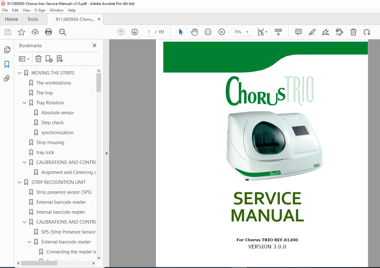
Download the official Chorus Trio service manual v3.0 for the REF 81200 model, providing detailed guidance on maintenance, calibration, troubleshooting, and repair of this immunoassay analyzer. This DIESSE Chorus Trio repair guide covers electronic parts, hydraulic circuits, optical units, and more in a high-quality PDF format with 151 pages. Essential Chorus Trio troubleshooting handbook for technicians handling clinical diagnostic instrument service.
Description
Chorus Trio Service Manual v3.0 – PDF DOWNLOAD
Description
The Chorus Trio service manual v3.0 is a comprehensive resource for technicians and service personnel maintaining the Chorus Trio REF 81200 immunoassay analyzer from DIESSE Diagnostica Senese SpA. This manual details the instrument’s operation, safety precautions, and step-by-step procedures for calibration, testing, and repair of key components like the transfer unit, optical system, washing circuits, and electronic boards. It emphasizes proper use to avoid malfunctions, with specific instructions for programming, maintenance routines, and fault diagnosis in the Chorus Trio troubleshooting handbook.
As a complete clinical diagnostic instrument service guide, it includes diagrams, control parameters, and functional tests to ensure optimal performance of the Chorus Trio parts and calibration manual. The manual corresponds to the 3.xx software family, ensuring compatibility with the instrument’s ID plate and software version.
File Details:
- Manual Name: Chorus Trio Service Manual v3.0
- Models Covered: Chorus Trio REF 81200
- Year: Not specified (Version 3.0, Revision 0)
- Manual PDF Quality: High-quality, searchable digital PDF with clear text and diagrams
- Number of Pages: 151
The manual features a detailed table of contents, neatly categorized for easy navigation:
- 1 Moving the Strips (Page 8)
- 1.1 The Workstations (Page 8)
- 1.2 The Tray (Page 9)
- 1.3 Tray Rotation (Page 9)
- 1.3.1 Absolute Sensor (Page 12)
- 1.3.2 Step Check (Page 12)
- 1.3.3 Synchronization (Page 13)
- 1.4 Strip Housing (Page 14)
- 1.5 Tray Lock (Page 15)
- 1.6 Calibrations and Control Parameters (Page 16)
- 1.6.1 Alignment and Centering of the Plate (Page 16)
- 2 Strip Recognition Unit (Page 17)
- 2.1 Strip Presence Sensor (SPS) (Page 17)
- 2.2 External Barcode Reader (Page 17)
- 2.3 Internal Barcode Reader (Page 18)
- 2.4 Calibrations and Control Parameters (Page 18)
- 2.4.1 SPS (Strip Presence Sensor) (Page 18)
- 2.4.2 External Barcode Reader (Page 19)
- 2.4.3 Internal Barcode Reader (Page 20)
- 3 Transfer Unit (Page 20)
- 3.1 Dispensing Hydraulic Circuit (Page 20)
- 3.2 The Strip, Needles and the Well (Page 21)
- 3.3 Dispenser (Page 22)
- 3.4 X-Axis Movement (Page 23)
- 3.5 The Syringe Unit (Page 23)
- 3.6 The Transfer Function (Page 25)
- 3.6.1 Transfer Function Parameters (Page 25)
- 3.6.2 The Double Dispensing Needle (Page 25)
- 3.6.3 Priming of the Dispensing and Wash Circuit (Page 26)
- 3.6.4 Withdrawal (Page 26)
- 3.6.5 Drying of the Tip (Page 28)
- 3.6.6 Perforation of the Cuvette Membrane (Page 28)
- 3.6.7 Level Detection (Page 29)
- 3.6.8 Mixing (Page 30)
- 3.6.9 Using a Prediluted Sample (Page 31)
- 3.6.10 Simple Transfer (Page 31)
- 3.7 Calibrations and Control Parameters (Page 33)
- 3.7.1 Circuit Transfer (Page 33)
- 3.7.2 Dispensers (Page 34)
- 3.7.3 X-Axis Movement (Page 35)
- 3.7.4 Level Sensors (Page 36)
- 3.8 Functional Tests (Page 37)
- 3.8.1 Transfer Test (Page 37)
- 3.8.2 Strip Perforation (Page 38)
- 4 Optical Unit (Page 40)
- 4.1 Light Source (Page 40)
- 4.2 The Optical Device (Page 41)
- 4.3 The Optical Channel (Page 41)
- 4.4 Positioning of Filters (Page 42)
- 4.5 Optical Calibration (Page 42)
- 4.5.1 Transmittance and Absorbance (Page 42)
- 4.5.2 Alignment of the Optical Fibres (Page 44)
- 4.5.3 Calibration of the Optical Channels (Page 46)
- 4.5.4 Calibration of the Dark Electronic Offset (Page 46)
- 4.5.5 Calibration of Light Emission (Page 47)
- 4.5.6 The Control Ramp (Page 48)
- 4.5.7 Report of the Virtual Ramp (Page 49)
- 4.5.8 Control Window (Page 51)
- 4.6 Optical Unit Testing Procedure (Page 52)
- 4.6.1 Setting of the Optical Filter Offset (Page 52)
- 4.6.2 Optical Channels (Page 52)
- 4.6.3 Checking of the Lamp’s Control Voltage (Page 52)
- 4.6.4 Calibrating the Offset (Dark Reading) (Page 53)
- 4.6.5 Calibrating the Light (Page 54)
- 4.6.6 Calibration Curve (Page 55)
- 5 Washing Unit (Page 58)
- 5.1 Hydraulic Wash Circuit (Page 58)
- 5.2 Tank Probes (Page 59)
- 5.3 The Washer (Page 60)
- 5.4 The Drying Station (Page 61)
- 5.5 Collection Wells (Page 62)
- 5.6 Washing Procedure (Page 63)
- 5.7 Washing Circuit Testing Procedure (Page 64)
- 5.7.1 Supplying of Buffer from Washer #1 (Page 64)
- 5.7.2 Supplying of Buffer from Washer #2 (Page 64)
- 5.7.3 Washing of the Piping for Washer #1 (Page 64)
- 5.7.4 Washing of the Piping for Washer #2 (Page 65)
- 5.7.5 Aspiration at Drying Station #3 (Page 65)
- 5.8 Control Parameters (Page 65)
- 5.8.1 Filling Level of Washer #1 (Page 65)
- 5.8.2 Filling Level of Washer #2 (Page 66)
- 6 The Drain Circuit (Page 67)
- 6.1 The Main Waste Well (Page 67)
- 6.1.1 Normal Operation (Page 68)
- 6.1.2 Obstructed Drain (Page 69)
- 6.1.3 Full Waste Tank (Page 69)
- 6.1.4 Faulty Drain Pump (Page 70)
- 6.2 Waste Circuit Testing Procedure (Page 70)
- 6.2.1 Checking of Waste Level Warning Sensor S3 (Page 70)
- 6.2.2 Checking of Error Sensor and Waste Level (Page 70)
- 6.1 The Main Waste Well (Page 67)
- 7 Temperature Control (Page 72)
- 7.1 Temperature Control of the Instrument (Page 72)
- 7.2 Measuring Chamber (Page 73)
- 7.3 Heater (Page 74)
- 7.3.1 Electrical Properties of the Heater (Page 74)
- 7.4 Cycle Temperature (Page 75)
- 7.5 Stand-By Temperature (Page 75)
- 7.6 Procedure for Testing the Temperature Control System (Page 75)
- 7.6.1 Checking of the Temperature Sensor (Page 75)
- 7.6.2 Chamber Temperature Control (Page 75)
- 7.6.3 Programming the Stand-By Temperature (Page 76)
- 8 Speaker-Printer Display (Page 77)
- 8.1 Display (Page 77)
- 8.2 The Speaker (Page 77)
- 8.3 The Printer (Page 78)
- 8.3.1 Printer Testing (Page 78)
- 9 Electronic Parts (Page 80)
- 9.1 General Map (Page 80)
- 9.2 CPU 2010 Board and Driver 2010 Board (Page 86)
- 9.2.1 Power Supply (Page 86)
- 9.2.2 Description of the Test Points and CPU 2010 Board Jumpers (Page 95)
- 9.2.3 Description of the Test Points and the Driver 2010 Board Jumpers (Page 96)
- 9.2.4 Troubleshooting (Page 97)
- 9.3 Low Power (Page 98)
- 9.3.1 Description (Page 98)
- 9.3.2 Power Supply and Connections (Page 98)
- 9.3.3 Troubleshooting (Page 103)
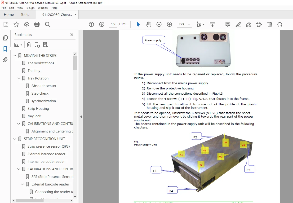
- 9.4 Power Supply (Page 104)
- 9.5 Description (Page 105)
- 9.5.1 Troubleshooting (Page 109)
- 9.6 Connectors Board (Page 110)
- 9.6.1 Description (Page 110)
- 9.6.2 Troubleshooting (Page 113)
- 10 Service Procedures (Page 114)
- 10.1 Programming CPU 2010 (Page 114)
- 10.1.1 Service Application (Page 114)
- 10.1.2 Connection with Chorus Trio Successful (Page 115)
- 10.1.3 Saving Methods (Page 117)
- 10.1.4 Connection with Chorus Trio Unsuccessful (Page 118)
- 10.1.5 Loading of Parameters and Methods (Page 120)
- 10.2 Programming the TC1100 (Page 123)
- 10.2.1 Prerequisites (Page 123)
- 10.2.2 Connecting the Reader to the PC (Page 123)
- 10.2.3 Installation of the Configuration Software (Page 123)
- 10.2.4 Launch the Configuration Program (Page 124)
- 10.2.5 Wiring Diagram of the Connection Cable (Page 127)
- 10.3 Programming the DLC6065 Barcode Reader (Page 128)
- 10.3.1 Connect the Reader to the Instrument Through the RS232 Cable (Page 128)
- 10.3.2 Disconnect the RS232 Cable (Page 129)
- 10.3.3 Enabling Serial Communication (Page 129)
- 10.4 Programming Barcode Reader Zebex Z 3080 (Page 130)
- 10.4.1 Connect the Reader to the Instrument Through the RS232 Cable (Page 130)
- 10.4.2 Disconnect the RS232 Cable (Page 130)
- 10.4.3 Programming Parameters (Page 131)
- System Setting (Page 132)
- Quick Setting (Page 133)
- 10.5 Maintenance (Page 134)
- 10.5.1 Routine Maintenance (Page 134)
- 10.5.2 Periodic Maintenance (Page 135)
- 10.5.3 Wash Well for the Dispenser Needles (Page 137)
- 10.5.4 Dispensers #1 and #2 (Page 138)
- 10.5.5 X-Axis Guide (Page 139)
- 10.5.6 Washers 21 – 25 – 28 (Page 140)
- 10.5.7 Optical Unit (Page 141)
- 10.5.8 Washer Wells (Page 145)
- 10.5.9 Upper Plate (Page 145)
- 10.5.10 Carousel (Page 146)
- 10.5.11 Peristaltic Pumps (Page 146)
- 10.5.12 Diaphragm Pump (Page 147)
- 10.5.13 Hydraulic Waste and Syringe Unit (Page 147)
- 10.5.14 Hydraulic Unit (Page 148)
- 10.5.15 Syringe Unit (Page 149)
- 10.5.16 Rotation (Page 150)
- 10.5.17 Tray Synchronization Device (Page 150)
- 10.5.18 Lamp Box and Filter Handler (Page 150)
- 10.5.19 Tank Probes (Page 151)
- 10.5.20 Tubing (Page 151)
- 10.1 Programming CPU 2010 (Page 114)
This immunoassay analyzer maintenance PDF is indispensable for ensuring accurate diagnostics and longevity of your Chorus Trio system through proper service and calibration.
Secure this essential manual now—download instantly to troubleshoot and maintain your Chorus Trio efficiently, minimizing downtime and repair costs