Claas-Atles 906 Tracktor Workshop Manual – PDF DOWNLOAD
Original price was: $78.00.$30.95Current price is: $30.95.
Claas-Atles 906 Tracktor Workshop Manual – PDF DOWNLOAD
Description
Claas-Atles 906 Tracktor Workshop Manual – PDF DOWNLOAD
IMAGES OF MANUAL :
TABLE OF CONTENTS:
Claas-Atles 906 Tracktor Workshop Manual – PDF DOWNLOAD
A1_GB………………………………………………………………………………………………………………………………………………. 1
A1 – INJECTION FEED………………………………………………………………………………………………………………………………. 1
Identification……………………………………………………………………………………………………………………………….. 2
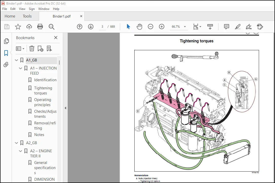
Tightening torques……………………………………………………………………………………………………………………………. 3
Operating principles………………………………………………………………………………………………………………………….. 4
Checks/Adjustments……………………………………………………………………………………………………………………………. 7
Removal/refitting…………………………………………………………………………………………………………………………….. 8
Notes……………………………………………………………………………………………………………………………………….. 12
A2_GB………………………………………………………………………………………………………………………………………………. 13
A2 – ENGINE TIER II………………………………………………………………………………………………………………………………. 13
General specifications………………………………………………………………………………………………………………………… 14
DIMENSIONAL SPECIFICATIONS…………………………………………………………………………………………………………………….. 15
Tightening torques……………………………………………………………………………………………………………………………. 18
Tightening torques……………………………………………………………………………………………………………………………. 19
Checks/Adjustments……………………………………………………………………………………………………………………………. 20
Removal/refitting…………………………………………………………………………………………………………………………….. 23
Notes……………………………………………………………………………………………………………………………………….. 40
TOOLS…………………………………………………………………………………………………………………………………………… 41
Tools for engine tier II………………………………………………………………………………………………………………………. 42
Notes……………………………………………………………………………………………………………………………………….. 44
AO_GB………………………………………………………………………………………………………………………………………………. 45
A0 – INJECTION SHEET CHECKING PROCEDURE…………………………………………………………………………………………………………….. 45
Checking procedure……………………………………………………………………………………………………………………………. 46
Measurement sheet…………………………………………………………………………………………………………………………….. 51
Pressure connection (appendix)…………………………………………………………………………………………………………………. 52
ATLES 926 – H 4522……………………………………………………………………………………………………………………………. 53
ATLES 936 – H 4532……………………………………………………………………………………………………………………………. 54
B1_GB………………………………………………………………………………………………………………………………………………. 57
B1 GBA 32 FULL POWERSHIFT GEARBOX………………………………………………………………………………………………………………….. 57
General……………………………………………………………………………………………………………………………………… 58
Notes……………………………………………………………………………………………………………………………………….. 63
General……………………………………………………………………………………………………………………………………… 64
Repair………………………………………………………………………………………………………………………………………. 69
Notes……………………………………………………………………………………………………………………………………….. 72
B2_GB………………………………………………………………………………………………………………………………………………. 73
B2 GTA 3230 LOW-PRESSURE HYDRAULIC CIRCUIT………………………………………………………………………………………………………….. 73
GBA 32 – General points……………………………………………………………………………………………………………………….. 74
GBA 32 repairs……………………………………………………………………………………………………………………………….. 80
GBA 32 measurement and checking points………………………………………………………………………………………………………….. 84
“Inspection results” sheet…………………………………………………………………………………………………………………….. 88
LS 110 l/min low-pressure circuit on GPA 30……………………………………………………………………………………………………… 89
Low-pressure hydraulic components………………………………………………………………………………………………………………. 94
Solenoid valve measurement and checking points…………………………………………………………………………………………………… 95
LS 110 l/min measurement and checking points…………………………………………………………………………………………………….. 97
“Hydraulic inspection results” sheet……………………………………………………………………………………………………………. 98
TOOLS…………………………………………………………………………………………………………………………………………… 99
Low-pressure hydraulics and gearbox tools………………………………………………………………………………………………………..100
Notes………………………………………………………………………………………………………………………………………..102
C1_GB……………………………………………………………………………………………………………………………………………….103
C1 – GPA 30 REAR AXLE……………………………………………………………………………………………………………………………..103
Tightening torques and main adjustments………………………………………………………………………………………………………….104
GPA 30 drive pinion……………………………………………………………………………………………………………………………109
Notes………………………………………………………………………………………………………………………………………..117
7″ differential……………………………………………………………………………………………………………………………….118
Notes………………………………………………………………………………………………………………………………………..129
Composite axle tubes…………………………………………………………………………………………………………………………..130
Double reduction axle tubes…………………………………………………………………………………………………………………….140
Notes………………………………………………………………………………………………………………………………………..149
GPA 30 power take-off clutch……………………………………………………………………………………………………………………150
GPA 30 power take-off upper shaft……………………………………………………………………………………………………………….156
GPA 30 power take-off lower shaft……………………………………………………………………………………………………………….158
GPA 30 crawler gears…………………………………………………………………………………………………………………………..164
C2_GB……………………………………………………………………………………………………………………………………………….169
C2 – SERVICE BRAKE AND HANDBRAKE……………………………………………………………………………………………………………………169
Technical specifications……………………………………………………………………………………………………………………….170
Brake pistons and seals………………………………………………………………………………………………………………………..171
Boosters and master cylinders…………………………………………………………………………………………………………………..175
Replacing the master cylinders………………………………………………………………………………………………………………….176
Bleeding the brake circuit……………………………………………………………………………………………………………………..177
Notes………………………………………………………………………………………………………………………………………..181
Handbrake…………………………………………………………………………………………………………………………………….182
C3_GB……………………………………………………………………………………………………………………………………………….187
C3 PARK LOCK……………………………………………………………………………………………………………………………………..187
Park Lock…………………………………………………………………………………………………………………………………….188
Schematic diagram of the Park Lock………………………………………………………………………………………………………………190
Park Lock…………………………………………………………………………………………………………………………………….192
“Inspection results” sheet……………………………………………………………………………………………………………………..196
D1_GB……………………………………………………………………………………………………………………………………………….197
D1 – FRONT AXLE 750.102 750.119…………………………………………………………………………………………………………………….197
Description…………………………………………………………………………………………………………………………………..198
Disassembly prior to front axle operations……………………………………………………………………………………………………….201
Removal/refitting……………………………………………………………………………………………………………………………..202
Hydraulic measurement and checking points………………………………………………………………………………………………………..228
“Hydraulic inspection results” sheet…………………………………………………………………………………………………………….229
Notes………………………………………………………………………………………………………………………………………..230
D2_GB……………………………………………………………………………………………………………………………………………….231
D2 – GPA 30 4-WHEEL DRIVE POWER TAKE-OFF HOUSING……………………………………………………………………………………………………..231
Description…………………………………………………………………………………………………………………………………..232
Removing/refitting the housing………………………………………………………………………………………………………………….236
Solenoid valve measurement and checking points……………………………………………………………………………………………………240
Hydraulic measurement and checking point…………………………………………………………………………………………………………241
“Hydraulic inspection results” sheet…………………………………………………………………………………………………………….242
TOOLS……………………………………………………………………………………………………………………………………………243
Front axle – 4 WD power take-off housing…………………………………………………………………………………………………………244
E1_GB……………………………………………………………………………………………………………………………………………….247
E1 CLOSED CENTRE HYDRAULICS (110 l/min)……………………………………………………………………………………………………………..247
Description…………………………………………………………………………………………………………………………………..248
Notes………………………………………………………………………………………………………………………………………..249
Removing/refitting the components……………………………………………………………………………………………………………….254
Notes………………………………………………………………………………………………………………………………………..293
Removing/refitting the components……………………………………………………………………………………………………………….294
Hydraulic measurement and checking points………………………………………………………………………………………………………..300
“Hydraulic inspection results” sheet…………………………………………………………………………………………………………….304
Hydraulic measurement and checking points………………………………………………………………………………………………………..307
“Hydraulic inspection results” sheet…………………………………………………………………………………………………………….310
TOOLS……………………………………………………………………………………………………………………………………………311
Hydraulic circuit tooling………………………………………………………………………………………………………………………312
F1_GB……………………………………………………………………………………………………………………………………………….313
F1 – ITEM LIST WIRING AND GENERAL LISTS……………………………………………………………………………………………………………..313
Item list…………………………………………………………………………………………………………………………………….314
Wiring and general lists……………………………………………………………………………………………………………………….315
SCHEMATIC DIAGRAMS ACCORDING TO ………………………………………………………………………………………………………………..317
CONTENTS……………………………………………………………………………………………………………………………………..318
Fuse and relay box…………………………………………………………………………………………………………………………….320
Fuse box and relay basic version………………………………………………………………………………………………………………..321
Conductor allocations………………………………………………………………………………………………………………………….321
Starting / charging / preheating circuit…………………………………………………………………………………………………………324
Dipped headlights – Headlights – Horn – Side lights – Instrument panel light…………………………………………………………………………325
Rotating beacons………………………………………………………………………………………………………………………………326
Front work lights……………………………………………………………………………………………………………………………..327
Rear work lights………………………………………………………………………………………………………………………………328
Transmission hydraulic pressure – Oil filter blocked (HP) – Oil filter blocked – (suction)…………………………………………………………….329
Theoretical speed……………………………………………………………………………………………………………………………..330
Instrument panel – Rear power take-off speed……………………………………………………………………………………………………..331
Notes………………………………………………………………………………………………………………………………………..332
Lift TCE – 15/25/35/ radar……………………………………………………………………………………………………………………..333
Electropilot (with TCE 15/25/35)………………………………………………………………………………………………………………..335
Clutch and drive control……………………………………………………………………………………………………………………….337
Park lock…………………………………………………………………………………………………………………………………….340
Gearbox control……………………………………………………………………………………………………………………………….341
Notes………………………………………………………………………………………………………………………………………..344
Engine management……………………………………………………………………………………………………………………………..345
Front axle engaging / differential and rear power take off…………………………………………………………………………………………347
Oil temperature sensors – Engine speed – Forward speed – Rear power take-off speed – …………………………………………………………………349
Cross control with solenoid pilot……………………………………………………………………………………………………………….350
Cross control…………………………………………………………………………………………………………………………………351
ADC – network…………………………………………………………………………………………………………………………………352
CONTENTS………………………………………………………………………………………………………………………………………… 0
Fuse and relay box F1.8………………………………………………………………………………………………………………………..317
Starting / charging / preheating circuit F1.12……………………………………………………………………………………………………317
Dipped headlights – Headlights – Horn – Side lights – Instrument panel light F1.13……………………………………………………………………317
Rotating beacons F1.14…………………………………………………………………………………………………………………………317
Front work lights F1.15………………………………………………………………………………………………………………………..317
Rear work lights F1.16…………………………………………………………………………………………………………………………317
Stop lights – Front axle engagement – Air brake system solenoid valve control F1.17…………………………………………………………………..317
Flashing lights and warning lights F1.18…………………………………………………………………………………………………………317
Cigar lighter – Clock – Radio – Cab light and spot F1.19…………………………………………………………………………………………..317
Pneumatic seat – Front power take off clutch F1.20………………………………………………………………………………………………..317
Front and rear windscreen wiper / washer F1.21……………………………………………………………………………………………………317
Instrument panel ventilation and air conditioning F1.22……………………………………………………………………………………………317
INFOTRAC on-board computer / ISO socket F1.24…………………………………………………………………………………………………….317
Fuel gauge – Engine temperature – Oil pressure – Air filter blocked F1.26……………………………………………………………………………317
Handbrake – Brake fluid level F1.27……………………………………………………………………………………………………………..317
Engine speed F1.28…………………………………………………………………………………………………………………………….317
Instrument panel calibration – Dashboard diagnostic socket F1.29……………………………………………………………………………………317
Electropilot diagnostic socket F1.30…………………………………………………………………………………………………………….317
25 A power socket F1.31………………………………………………………………………………………………………………………..317
Transmission hydraulic pressure – Oil filter blocked (HP) – Oil filter blocked (suction) F1.32…………………………………………………………317
Theoretical speed F1.33………………………………………………………………………………………………………………………..317
Instrument panel – Rear power take-off speed F1.34………………………………………………………………………………………………..317
Lift TCE – 15/25/35/ radar F1.36………………………………………………………………………………………………………………..317
Electropilot (with TCE 15/25/35) F1.38…………………………………………………………………………………………………………..317
Clutch and drive control F1.40………………………………………………………………………………………………………………….317
Park Lock F1.43……………………………………………………………………………………………………………………………….317
Gearbox control F1.44………………………………………………………………………………………………………………………….317
Engine management F1.48………………………………………………………………………………………………………………………..317
Front axle engaging – Differential and rear power take off F1.50……………………………………………………………………………………317
Oil temperature sensors – Engine speed – Forward speed – Rear power take-off speed – Reverser module speed – Drivetronic F1.52…………………………….317
Cross control with solenoid pilot F1.53………………………………………………………………………………………………………….317
Cross control F1.54……………………………………………………………………………………………………………………………317
ADC – network F1.55……………………………………………………………………………………………………………………………317
F2_GB……………………………………………………………………………………………………………………………………………….354
F2 – HARNESS AND CONNECTOR PATHS……………………………………………………………………………………………………………………354
CONTENTS……………………………………………………………………………………………………………………………………..355
Harness and connector paths…………………………………………………………………………………………………………………….356
1 – Instrument panel harness……………………………………………………………………………………………………………………357
Notes………………………………………………………………………………………………………………………………………..364
2 – Preheating harness…………………………………………………………………………………………………………………………365
3a – Front harness…………………………………………………………………………………………………………………………….366
Radiator cowling harness……………………………………………………………………………………………………………………….367
4a – Additional computer harness………………………………………………………………………………………………………………..368
4b – Engine control harness…………………………………………………………………………………………………………………….368
4c – Additional engine harness………………………………………………………………………………………………………………….369
Notes………………………………………………………………………………………………………………………………………..370
5 – Instrument panel / cab top harness…………………………………………………………………………………………………………..371
5a – Cab top / front lights harness……………………………………………………………………………………………………………..375
5b – Cab top / rear light harness with air conditioning……………………………………………………………………………………………377
Notes………………………………………………………………………………………………………………………………………..378
5c – Front and rear light harness……………………………………………………………………………………………………………….379
Notes………………………………………………………………………………………………………………………………………..382
6 – Rear harness………………………………………………………………………………………………………………………………383
7a – GTA 303 transmission link harness…………………………………………………………………………………………………………..387
7b – GTA 303 transmission harness……………………………………………………………………………………………………………….389
Notes………………………………………………………………………………………………………………………………………..392
8 – FPS transmission control harness…………………………………………………………………………………………………………….393
8/1 – ISO socket harness……………………………………………………………………………………………………………………….398
8/2 – Display harness………………………………………………………………………………………………………………………….398
9a – TCE 15/25/35 Control harness……………………………………………………………………………………………………………….399
Notes………………………………………………………………………………………………………………………………………..402
9/1a – TCE 15 /25/35 Harness……………………………………………………………………………………………………………………403
9/2a – Cross control ha rness with Electropilot…………………………………………………………………………………………………..405
9/3 – Electrohydraulic spool valve control harness………………………………………………………………………………………………..407
10 – On-board computer harness………………………………………………………………………………………………………………….409
TOOLS………………………………………………………………………………………………………………………………………..410
G1_GB……………………………………………………………………………………………………………………………………………….411
G1 – INSTRUMENT PANEL……………………………………………………………………………………………………………………………..411
Operating principles…………………………………………………………………………………………………………………………..412
Characteristics……………………………………………………………………………………………………………………………….414
Removal/refitting……………………………………………………………………………………………………………………………..430
Calibration…………………………………………………………………………………………………………………………………..431
G2_GB……………………………………………………………………………………………………………………………………………….433
G2 – TCE 25 ELECTRONIC LIFT………………………………………………………………………………………………………………………..433
Description…………………………………………………………………………………………………………………………………..434
Checks and adjustments…………………………………………………………………………………………………………………………436
Notes………………………………………………………………………………………………………………………………………..442
G3_GB……………………………………………………………………………………………………………………………………………….443
G3 – TRANSMISSION/AXLE CONTROL……………………………………………………………………………………………………………………..443
Full Powershift……………………………………………………………………………………………………………………………….444
G4_GB……………………………………………………………………………………………………………………………………………….463
G4 – ENGINE MANAGEMENT…………………………………………………………………………………………………………………………….463
Engine management……………………………………………………………………………………………………………………………..464
Notes………………………………………………………………………………………………………………………………………..472
G5_GB……………………………………………………………………………………………………………………………………………….473
G5 – INFOTRAC AND ISO SOCKET……………………………………………………………………………………………………………………….473
Description…………………………………………………………………………………………………………………………………..474
Removal/refitting and electrical checks………………………………………………………………………………………………………….478
Notes………………………………………………………………………………………………………………………………………..486
G6_GB……………………………………………………………………………………………………………………………………………….487
G6 – ELECTROPILOT…………………………………………………………………………………………………………………………………487
Description…………………………………………………………………………………………………………………………………..488
Removal/refitting……………………………………………………………………………………………………………………………..492
Measurement and checking points…………………………………………………………………………………………………………………493
“Inspection results” sheet……………………………………………………………………………………………………………………..495
Notes………………………………………………………………………………………………………………………………………..496
TOOLS………………………………………………………………………………………………………………………………………..497
Instrument panel – TCE 15 / 2 5 and TCE 15 T electronic lift – Transmission/axle control – ……………………………………………………………498
Notes………………………………………………………………………………………………………………………………………..500
G7_GB……………………………………………………………………………………………………………………………………………….501
G7 WIN METADIAG© MANUAL ATLES 906…………………………………………………………………………………………………………………..501
CONTENTS……………………………………………………………………………………………………………………………………..503
WIN METADIAG© ATLES 906 MANUAL………………………………………………………………………………………………………………….505
Connecting Win Métadiag©……………………………………………………………………………………………………………………….506
Engine application…………………………………………………………………………………………………………………………….508
Transmission application……………………………………………………………………………………………………………………….514
Rear lift application………………………………………………………………………………………………………………………….530
Dashboard application………………………………………………………………………………………………………………………….534
Electropilot application……………………………………………………………………………………………………………………….537
H1_GB……………………………………………………………………………………………………………………………………………….545
H1 CAB LIFT………………………………………………………………………………………………………………………………………545
Description…………………………………………………………………………………………………………………………………..546
Full cab removal………………………………………………………………………………………………………………………………549
Removal/refitting……………………………………………………………………………………………………………………………..550
Refitting the cab……………………………………………………………………………………………………………………………..558
Removing/refitting the roof…………………………………………………………………………………………………………………….560
H2_GB……………………………………………………………………………………………………………………………………………….561
H2 HEATING/AIR CONDITIONING………………………………………………………………………………………………………………………..561
Description…………………………………………………………………………………………………………………………………..562
Removal/refitting……………………………………………………………………………………………………………………………..566
Notes………………………………………………………………………………………………………………………………………..576
Troubleshooting Guide………………………………………………………………………………………………………………………….577
H3_GB……………………………………………………………………………………………………………………………………………….579
H3 BONDING THE WINDOWS…………………………………………………………………………………………………………………………….579
Removal/refitting……………………………………………………………………………………………………………………………..580
Notes………………………………………………………………………………………………………………………………………..588
TOOLS………………………………………………………………………………………………………………………………………..589
Cab lifting – Heating/air conditioning – Glass bonding equipment……………………………………………………………………………………590
Notes………………………………………………………………………………………………………………………………………..592
J1_GB……………………………………………………………………………………………………………………………………………….593
J1 – LIFT AND FRONT POWER TAKE-OFF………………………………………………………………………………………………………………….593
Front linkage…………………………………………………………………………………………………………………………………594
Measurement and checking points…………………………………………………………………………………………………………………597
“Inspection results” sheet……………………………………………………………………………………………………………………..598
Front power take-off…………………………………………………………………………………………………………………………..599
Measurement and checking points…………………………………………………………………………………………………………………607
“Inspection results” sheet……………………………………………………………………………………………………………………..608
J2_GB……………………………………………………………………………………………………………………………………………….609
J2 – PNEUMATIC BRAKING…………………………………………………………………………………………………………………………….609
Notes………………………………………………………………………………………………………………………………………..610
How it works………………………………………………………………………………………………………………………………….611
Main components……………………………………………………………………………………………………………………………….618
Notes………………………………………………………………………………………………………………………………………..622
TOOLS………………………………………………………………………………………………………………………………………..623
Lift, front power take-off and pneumatic braking tools…………………………………………………………………………………………….624
SOM_A_GB…………………………………………………………………………………………………………………………………………….625
Chapter A………………………………………………………………………………………………………………………………………..625
Som_ARES506-606………………………………………………………………………………………………………………………………………629
SOM_B_GB…………………………………………………………………………………………………………………………………………….630
Chapter B………………………………………………………………………………………………………………………………………..630
SOM_C_GB…………………………………………………………………………………………………………………………………………….634
Chapter C………………………………………………………………………………………………………………………………………..634
SOM_D_GB…………………………………………………………………………………………………………………………………………….640
Chapter D………………………………………………………………………………………………………………………………………..640
SOM_E_GB…………………………………………………………………………………………………………………………………………….644
Chapter E………………………………………………………………………………………………………………………………………..644
SOM_F_GB…………………………………………………………………………………………………………………………………………….648
Chapter F………………………………………………………………………………………………………………………………………..648
SOM_G_GB…………………………………………………………………………………………………………………………………………….654
Chapter G………………………………………………………………………………………………………………………………………..654
CONTENTS………………………………………………………………………………………………………………………………………… 0
G1 – Instrument panel………………………………………………………………………………………………………………………….656
Operating principles…………………………………………………………………………………………………………………………..656
Description of panel G1.2…………………………………………………………………………………………………………………..656
Allocation of light bulbs to indicator lights G1.3…………………………………………………………………………………………….656
Characteristics……………………………………………………………………………………………………………………………….656
Indicator operation G1.4……………………………………………………………………………………………………………………656
Warning lights (red) G1.9…………………………………………………………………………………………………………………..656
Secondary warning lights (orange) G1.10………………………………………………………………………………………………………656
Other indicator lights G1.10………………………………………………………………………………………………………………..656
Input/output by function (rev counter, various speeds and hour counter) G1.11…………………………………………………………………….656
Input/output by function (gauge and temperature) G1.12…………………………………………………………………………………………656
Inputs/outputs relating to red lights G1.13…………………………………………………………………………………………………..656
Inputs/outputs relating to other lights G1.14…………………………………………………………………………………………………656
Connection and functions of the wires of the single connector “JX1” G1.15………………………………………………………………………..656
Connection and functions of the wires of the double connector “JX2” G1.16………………………………………………………………………..656
Transmission oil pressure sensor (17 bar) G1.18……………………………………………………………………………………………….656
Blockage indicator G1.18……………………………………………………………………………………………………………………656
Engine oil pressure sensor G1.18…………………………………………………………………………………………………………….656
Transmission oil temperature sensor G1.18…………………………………………………………………………………………………….656
Speed sensors G1.19………………………………………………………………………………………………………………………..656
Removal/refitting……………………………………………………………………………………………………………………………..656
Connectors “JX1” and “JX2” G1.20…………………………………………………………………………………………………………….656
Calibration…………………………………………………………………………………………………………………………………..656
Calibration over 100 metres G1.21……………………………………………………………………………………………………………656
Other operations G1.22……………………………………………………………………………………………………………………..656
G2 – TCE 25 electronic lift…………………………………………………………………………………………………………………….656
Description…………………………………………………………………………………………………………………………………..656
TCE 25 G2.2……………………………………………………………………………………………………………………………….656
Access to the installed software version (TCE 25) G2.3…………………………………………………………………………………………656
Lift operating conditions G2.3………………………………………………………………………………………………………………657
Error codes G2.3…………………………………………………………………………………………………………………………..657
Checks and adjustments…………………………………………………………………………………………………………………………657
Connections to TCE 25 unit G2.4……………………………………………………………………………………………………………..657
Position sensor G2.5……………………………………………………………………………………………………………………….657
Load sensors G2.6………………………………………………………………………………………………………………………….657
Theoretical forward speed sensor G2.8………………………………………………………………………………………………………..657
Radar G2.9………………………………………………………………………………………………………………………………..657
Lift spool valve solenoid valves G2.9………………………………………………………………………………………………………..657
G3 – Transmission/axle control………………………………………………………………………………………………………………….657
Full Powershift……………………………………………………………………………………………………………………………….657
Location of components and sensors G3.2………………………………………………………………………………………………………657
Layout on the rear axle G3.4………………………………………………………………………………………………………………..657
Features/settings G3.5……………………………………………………………………………………………………………………..657
Clutch pedal switches G3.7………………………………………………………………………………………………………………….657
Adjustment of TOC, BOC and angle detector switches G3.12……………………………………………………………………………………….657
Schematic diagram of TC/RCC G3.14……………………………………………………………………………………………………………657
G4 – Engine management…………………………………………………………………………………………………………………………657
Engine management……………………………………………………………………………………………………………………………..657
Location of the components G4.2……………………………………………………………………………………………………………..657
Characteristics of the components G4.3……………………………………………………………………………………………………….657
Schematic diagram G4.7……………………………………………………………………………………………………………………..657
Adjusting the accelerator detector G4.9………………………………………………………………………………………………………657
G5 – Infotrac and ISO socket……………………………………………………………………………………………………………………657
Description…………………………………………………………………………………………………………………………………..657
Functions of the on-board computer G5.2………………………………………………………………………………………………………657
Operating principles G5.2…………………………………………………………………………………………………………………..657
Use G5.4………………………………………………………………………………………………………………………………….657
Removal/refitting and electrical checks………………………………………………………………………………………………………….658
Removing the unit and changing the bulbs G5.6…………………………………………………………………………………………………658
ISO socket G5.7……………………………………………………………………………………………………………………………658
ISO unit G5.7……………………………………………………………………………………………………………………………..658
External temperature probe G5.7……………………………………………………………………………………………………………..658
Schematic diagram G5.9……………………………………………………………………………………………………………………..658
Functions of connector wires G5.10…………………………………………………………………………………………………………..658
Electrical check on the ISO socket G5.11……………………………………………………………………………………………………..658
Outside air temperature sensor G5.12…………………………………………………………………………………………………………658
Forward speed calibration G5.13……………………………………………………………………………………………………………..658
Maintenance function G5.13………………………………………………………………………………………………………………….658
G6 – Electropilot……………………………………………………………………………………………………………………………..658
Description…………………………………………………………………………………………………………………………………..658
Controls G6.2……………………………………………………………………………………………………………………………..658
Joystick connections G6.3…………………………………………………………………………………………………………………..658
DC power switch connections G6.3…………………………………………………………………………………………………………….658
Connections on module G6.4………………………………………………………………………………………………………………….658
Electrohydraulic spool valve (“DEH”) G6.5…………………………………………………………………………………………………….658
Removal/refitting……………………………………………………………………………………………………………………………..658
Electrohydraulic spool valve (“DEH”) G6.6…………………………………………………………………………………………………….658
Measurement and checking points…………………………………………………………………………………………………………………658
Checking the safety solenoid valve G6.7………………………………………………………………………………………………………658
Checking the control pressures G6.8………………………………………………………………………………………………………….658
“Inspection results” sheet……………………………………………………………………………………………………………………..658
Checking the safety solenoid valve G6.9………………………………………………………………………………………………………658
Checking the control pressure G6.9…………………………………………………………………………………………………………..658
Tools………………………………………………………………………………………………………………………………………..658
Instrument panel – TCE 15/25 and TCE 15 T electronic lift – Transmission/axle control – Engine management – Infotrac and ISO socket – Electropilot G6.12….658
G7 – Win Metadiag© ATLES 906 Manual……………………………………………………………………………………………………………..659
Connecting Win Metadiag©……………………………………………………………………………………………………………………….659
Engine application G7.2…………………………………………………………………………………………………………………….659
Transmission/Electropilot application G7.2……………………………………………………………………………………………………659
Dashboard application G7.2………………………………………………………………………………………………………………….659
TCE 25 application G7.3…………………………………………………………………………………………………………………….659
Engine application…………………………………………………………………………………………………………………………….659
Win Metadiag© engine application G7.4………………………………………………………………………………………………………..659
Transmission application……………………………………………………………………………………………………………………….659
Full Powershift G7.10………………………………………………………………………………………………………………………659
“RCC” and “TC” fault history G7.16…………………………………………………………………………………………………………..659
Rear lift application………………………………………………………………………………………………………………………….659
TCE 25 G7.26………………………………………………………………………………………………………………………………659
Dashboard application………………………………………………………………………………………………………………………….659
Dashboard application G7.30…………………………………………………………………………………………………………………659
Electropilot application……………………………………………………………………………………………………………………….659
Electropilot application G7.33………………………………………………………………………………………………………………659
SOM_H_GB…………………………………………………………………………………………………………………………………………….66
Chapter H………………………………………………………………………………………………………………………………………..660
SOM_J_GB…………………………………………………………………………………………………………………………………………….664
Chapter J………………………………………………………………………………………………………………………………………..664
SYMB_GB……………………………………………………………………………………………………………………………………………..668
Symbols………………………………………………………………………………………………………………………………………….668
Fixing and sealing products………………………………………………………………………………………………………………………..668
Hydraulic lines…………………………………………………………………………………………………………………………………..668
Standardised torques………………………………………………………………………………………………………………………………669
PLEASE NOTE:
- This is the exact same manual used by your dealerships to service your vehicle.
- The same can be yours in the next 2-3 minutes as you will be directed to the download page immediately after paying for the manual.
- For any questions / doubts regarding your purchase, please do not hesitate to contact [email protected]
S.M.