Claas Baler Quadrant 2200 Roto Cut 2200 Roto Cut HD 2200 FINE Cut Operator’s Manual – PDF DOWNLOAD
Original price was: $89.95.$29.95Current price is: $29.95.
Claas Baler Quadrant 2200 Roto Cut 2200 Roto Cut HD 2200 FINE Cut Operator’s Manual – PDF DOWNLOAD
Description
Claas Baler Quadrant 2200 Roto Cut 2200 Roto Cut HD 2200 FINE Cut Operator’s Manual – PDF DOWNLOAD
DESCRIPTION:
Claas Baler Quadrant 2200 Roto Cut 2200 Roto Cut HD 2200 FINE Cut Operator’s Manual – PDF DOWNLOAD
INTRODUCTION :
This manual contains information regarding the use, setting and operation of the big square balers CLAAS QUADRANT 2200, QUADRANT 2200 ROTO CUT, QUADRANT 2200 ROTO CUT HD and QUADRANT 2200 FINE CUT Provided you follow the advice on the care and servicing of your machine you will be rewarded with reliable operating efficiency and long service from your square baler.
- We recommend that you allow your local CLAAS Dealer to overhaul and service your big square baler immediately after the season, adhering to the recommended winter service schedule contained in this manual.
- Omissions of parts of a service, or incorrect adjustments lead to a drop in performance and cost valuable time. By correct servicing and operation you can make full use of the latest technical knowledge and experience in mechanised handling of forage and straw with which your machine has been designed, and thereby ensure reliability of your big square baler.
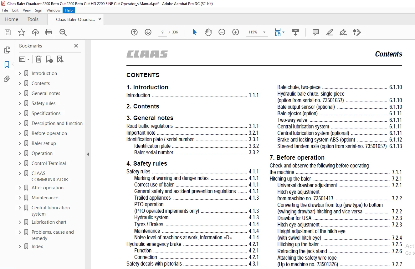
TABLE OF CONTENTS:
Claas Baler Quadrant 2200 Roto Cut 2200 Roto Cut HD 2200 FINE Cut Operator’s Manual – PDF DOWNLOAD
1 Introduction
Introduction 1 1 1
2 Contents
3 General notes
Road traffic regulations 3 1 1
Important note 3 2 1
Identification plate / serial number 3 3 1
Identification plate 3 3 2
Baler serial number 3 3 2
4 Safety rules
Safety rules 4 1 1
Marking of warning and danger notes 4 1 1
Correct use of baler 4 1 1
General safety and accident prevention regulations 4 1 1
Trailed appliances 4 1 3
PTO operation
(PTO operated implements only) 4 1 3
Hydraulic system 4 1 3
Tyres / Brakes 4 1 4
Maintenance 4 1 4
Noise level of machines at work, information »D« 4 1 4
Hydraulic emergency brake 4 2 1
Function 4 2 1
Connection 4 2 1
Safety decals with pictorials 4 3 1
5 Specifications
CLAAS Quadrant 2200 / 2200 RC / 2200 RC HD / 2200 FC 5 1 1
Safety features 5 2 1
6 Description and function
Machine overview 6 1 1
Power transmission 6 1 1
Free wheeling slip clutch 6 1 1
Mechanical flywheel brake 6 1 2
Hydraulic flywheel brake (option) 6 1 2
Pick up 6 1 3
Swath spreader (optional) 6 1 3
Roller crop press (optional) 6 1 4
Short crop baffle (optional) 6 1 4
Cutting facility (QUADRANT 2200 RC) 6 1 4
Cutting facility (QUADRANT 2200 FC) 6 1 5
Feed rake 6 1 6
Turbo plate (optional) 6 1 7
Feed rake drive 6 1 7
Rotor drive 6 1 7
Ram and baling channel 6 1 7
Moisture sensor (optional) 6 1 8
Baling pressure control 6 1 8
Baling pressure overload protection 6 1 8
Tying mechanism 6 1 9
Knotter cleaning unit (standard) 6 1 9
Turbofan (optional) 6 1 9
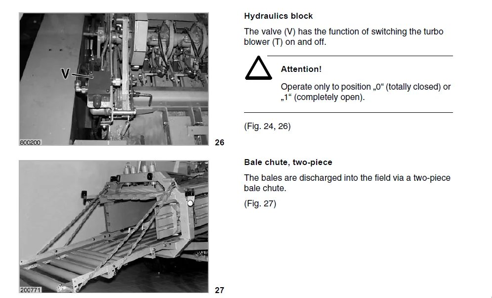
Hydraulics block 6 1 10
Bale chute, two-piece 6 1 10
Hydraulic bale chute, single piece
(option from serial-no 73501657) 6 1 10
Bale output sensor (optional) 6 1 10
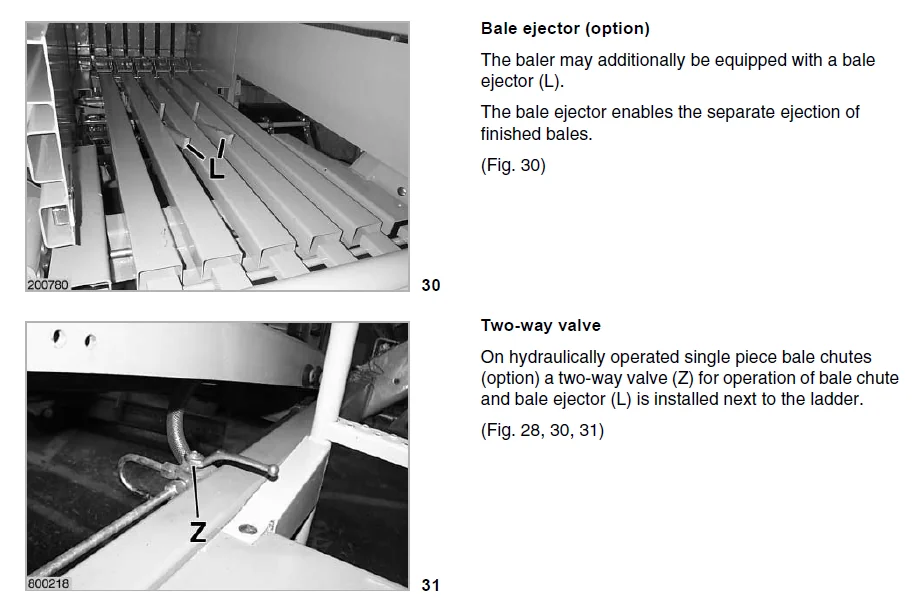
Bale ejector (option) 6 1 11
Two-way valve 6 1 11
Central lubrication system 6 1 11
Central lubrication system (optional) 6 1 11
Brake anti locking system ABS (option) 6 1 12
Steered tandem axle (option from serial-no 73501657) 6 1 13
7 Before operation
Check and observe the following before operating
the machine 7 1 1
Hitching up the baler 7 2 1
Universal drawbar adjustment 7 2 1
Hitch eye adjustment
from machine no 73501417 7 2 2
Converting the drawbar from top (jaw type) to bottom
(swinging drawbar) hitching and vice versa 7 2 2
Drawbar for USA 7 2 3
Hitch eye adjustment 7 2 3
Height adjustment of the hitch eye
(with swivel hitch eye) 7 2 4
Hitching up the baler 7 2 5
Retracting the jack stand 7 2 6
Attaching the safety wire rope
(Up to machine no 73501326) 7 2 7
Fitting the universal drive shafts 7 2 7
Connecting the universal drive shaft to the baler 7 2 7
Fitting the universal drive shaft to the tractor 7 2 8
Swashing range and clearance area 7 2 8
Shortening the universal drive shaft 7 3 1
Refitting the starprofiled tube lubricating device 7 3 1
Modification procedure
(Male guard / female starprofiled
tube – on baler) 7 3 2
Modification procedure
(Centre support of the guard) 7 3 2
Modification procedure
(Female guard – on tractor) 7 3 3
Preventing the propshaft at the protection funnel
from rotating with the drive shaft 7 3 4
Brakes 7 4 1
Air operated brakes 7 4 1
Hydraulic emergency brake 7 4 2
Connection 7 4 2
Maneuvering the baler without air operated brake 7 4 3
Hydraulic braking system 7 4 3
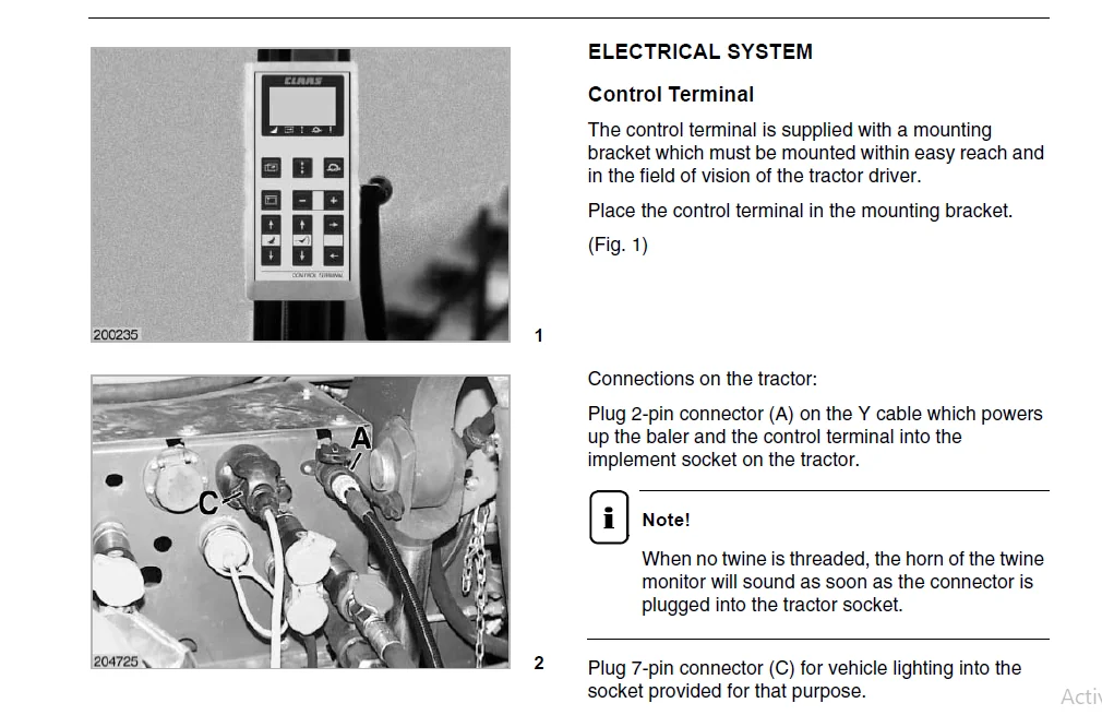
Electrical system 7 5 1
Control Terminal 7 5 1
CLAAS COMMUNICATOR 7 5 2
Central terminal compartment 7 5 5
12 volt socket 7 5 5
Equipment 7 6 1
Ladder 7 6 1
Roller chute 7 6 1
Contents
2 1 2 BA Quadrant 2200 – 2200 RC – 2200 RC HD – 2200 FC – 000 294 233 0
Contents
Bale chute locking device 7 6 1
Hydraulic bale chute (option from serial-no 73501657) 7 6 2
Pickup gauge wheels 7 6 2
Before transporting the baler 7 7 1
8 Baler set up
Pick up 8 1 1
Pick-up height adjustment 8 1 1
Adjusting the working height of the pick up 8 1 2
Pick up with gauge wheels 8 1 2
Gauge wheels 8 1 3
Pick up crop guard with short crop baffle 8 1 4
Adjusting the roller crop press 8 1 5
Roller crop press and swath distributor 8 1 9
Raising the bale chamber bottom 8 1 9
Cutting device (RC) 8 1 10
Removing knives RC and FC: 8 1 10
Dummy knife holder (optional) 8 1 13
Dummy blades 8 1 13
Adjusting two-piece bale chute 8 1 13
Adjusting the hydraulic bale chute (option) 8 1 13
Tying 8 2 1
Twine boxes 8 2 1
Thread up the twine 8 2 1
Adjusting twine run 8 2 4
9 Operation
Starting work 9 1 1
Guide to pressure settings 9 1 2
Free wheeling slip clutch 9 1 3
Feed rake overload 9 1 4
Rotor overload 9 1 5
Electrical twine monitor 9 1 6
Bale ejector (option) 9 1 7
Lifting/lowering the bale chute 9 1 8
Turbofan (Option) 9 1 8
Hydraulic flywheel brake (option) 9 1 9
Emergency controls
(QUADRANT 2200 to machine no 73501416
QUADRANT 2200 RC to machine no 73501266) 9 2 1
Controls for emergency operation 9 2 1
Setting the baling pressure 9 2 3
Setting the bale length 9 2 4
Discharging bales 9 2 5
Engaging and disengaging knives 9 2 5
Opening and closing the cutting floor 9 2 6
Emergency operation
(QUADRANT 2200 with CLAAS COMMUNICATOR) 9 3 1
10 Control Terminal
Control Terminal – overview 10 1 1
Display 10 1 2
Setting 10 2 1
Setting the bale length 10 2 1
Setting the baling pressure 10 2 2
Adjusting the bale shape (option) 10 2 3
Operator settings 10 3 1
Select the operator settings submenu 10 3 1
Using the operator settings 10 3 1
Setting the knotter cleaning (air blast) time 10 3 2
Length of knotter air blast time 10 3 3
Setting the lubrication interval 10 3 4
Knife cleaning 10 3 4
Language selection 10 3 5
Bale length correction factor 10 3 6
Display readings in the various languages 10 3 7
Counter 10 4 1
Daily and total counter 10 4 1
Resetting the maintenance schedule display 10 4 2
Resetting the daily counter 10 4 2
Special counter 10 4 3
Starting the special counter 10 4 3
Bale counter correction 10 4 4
Resetting work records 10 4 4
Fault display 10 5 1
Operation 10 6 1
Decreasing or increasing the pressure 10 6 1
Starting manual tying 10 6 1
Engaging and disengaging knives 10 6 2
Raising and lowering of the cutting floor 10 6 2
Starting the lubrication system manually 10 6 3
11 CLAAS COMMUNICATOR
CLAAS COMMUNICATOR – overview 11 1 1
Switching on the Claas Communicator 11 1 1
Overview 11 1 2
Keys and incremental encoder 11 1 3
Incremental encoder 11 1 3
Display 11 1 4
Application menu 11 1 4
Setup menu 11 1 6
Counter menu 11 1 7
Fault menu 11 1 8
System information menu 11 1 8
Settings in the application menu 11 2 1
Setting the bale length 11 2 1
Setting the baling pressure 11 2 2
Selecting a job 11 2 2
Operator settings 11 3 1
Opening the adjustment menu 11 3 1
Setting the bale length 11 3 1
Bale length correction factor 11 3 2
Setting the baling pressure 11 3 3
Setting the knotter cleaning time 11 3 4
Activating the cutting blade sequence 11 3 5
Setting the lubrication interval
(Claas Communicator without and with ISOBUS) 11 3 6
Manually controlled lubrication
(Claas Communicator with ISOBUS) 11 3 6
Counter 11 4 1
Opening the counter menu 11 4 1
Selecting job orders 11 4 1
Resetting the order (zero setting) 11 4 1
Resetting the daily counter 11 4 2
Resetting the service display 11 4 2
Fault 11 5 1
Fault display 11 5 1
000 294 233 0 – BA Quadrant 2200 – 2200 RC – 2200 RC HD – 2200 FC 2 1 3
Contents
Tying fault
(Claas Communicator without ISOBUS) 11 5 3
When starting the Claas Communicator 11 5 3
During work 11 5 3
Tying fault
(Claas Communicator without ISOBUS) 11 5 3
Tying fault 26 11 5 4
Tying fault 27/28/29 11 5 4
Service menu 11 6 1
Opening the service menu 11 6 1
Image adjustment menu 11 6 3
Changing the contrast of the screen 11 6 3
Opening the time and date menu 11 6 4
Setting time/date 11 6 4
Opening the memory management menu 11 6 5
Deleting memory 11 6 5
Opening the language selection menu 11 6 6
Setting the language selection menu 11 6 6
Opening the Aux menu 11 6 7
Operation 11 7 1
Building up/relieving the baling pressure 11 7 1
Starting manual wrapping 11 7 1
Swivelling cutting blades in/out 11 7 2
Cutting frame up/down 11 7 3
Controlling manual lubrication
(Claas Communicator with ISOBUS) 11 7 4
12 After operation
Unhitching the baler 12 1 1
Parking brake 12 1 1
Wheel chocks 12 1 1
Jack stand 12 1 2
Uncouple the hydraulic oil hoses from the
hydraulic brakes 12 1 3
Electrical connections 12 1 3
Disconnecting the air hoses 12 1 4
Storage of universal drive shaft 12 1 4
Cleaning the baler 12 1 5
General 12 1 5
Structure and interior of baler 12 1 5
Knotter 12 1 5
Piston rod 12 1 5
13 Maintenance
Important maintenance instructions 13 1 1
Important maintenance instructions and
safety regulations 13 1 1
Maintenance schedule 13 2 1
Lubricants chart 13 3 1
Brake system 13 4 1
Air operated brakes 13 4 1
Drain air reservoir 13 4 2
Brake cylinder 13 4 2
Adjusting the brake lever 13 4 2
Hydraulic braking system 13 4 3
Brake cylinder 13 4 3
Adjusting the brake lever 13 4 3
Brake linings 13 4 4
Brake anti locking system (ABS) (option) 13 4 4
Draining water from the air reservoir for the ABS 13 4 4
Tyres 13 5 1
Check tight fit of wheel nuts 13 5 1
Checking wheel hub backlash 13 5 1
Adjusting the backlash 13 5 1
Hydraulic system 13 6 1
Check oil level 13 6 1
Oil change 13 6 2
Changing the hydraulic oil filter 13 6 2
Drives 13 7 1
Main gearbox 13 7 1
Gearbox – hydraulic pump drive 13 7 1
Transfer gearbox – rotor / feed rake drive 13 7 2
Upper gearbox – rotor drive 13 7 2
Lower gearbox – rotor drive 13 7 3
Gearbox – knotter drive 13 7 3
Overload clutches and shear bolts 13 7 3
Free wheeling slip clutch 13 7 4
Main drive 13 7 4
Pick-up drive 13 7 6
Knotter shaft drive 13 7 7
Tying release, checking and adjustment 13 7 9
Drive chains 13 8 1
Tensioning the drive chain for the pick-up drive 13 8 1
Tensioning the drive chain for the feed auger 13 8 1
Adjusting the springs of the twine retainers 13 8 2
Adjusting the springs of the knotter hooks 13 8 2
Knotter shaft brake 13 8 3
Adjusting the knotter pinion for correct play 13 8 3
Needle carrier brakes 13 8 4
Knotter cleaning unit (standard) 13 8 4
Servicing the air filter 13 8 5
Changing the filter cartridge 13 8 6
V-belt tension
(up to serial-no 73502778) 13 8 6
Checking the compressor console is secure
(up to serial-no 73502778) 13 8 7
Checking the oil level of the compressor
(up to serial-no 73502778) 13 8 8
Changing the compressor’s oil
(up to serial-no 73502778) 13 8 8
Draining water from the air reservoir for the
knotter cleaning 13 8 9
Turbofan (Option) 13 8 9
Check oil level 13 8 9
Oil change 13 8 10
Changing the hydraulic oil filter 13 8 10
Test accumulator 13 8 11
Depressurising the system 13 8 11
Basic setting 13 9 1
Setting the drives to the timing marks 13 9 1
Tying mechanism 13 10 1
Adjusting knotter shaft and needles 13 10 1
Adjusting the needle height: 13 10 2
Adjusting the top dead centre position of needles: 13 10 2
Checking the needle position relative to the ram 13 10 3
Fine tuning via tying gear 13 10 4
Correct the adjustment via the universal shaft: 13 10 4
2 1 4 BA Quadrant 2200 – 2200 RC – 2200 RC HD – 2200 FC – 000 294 233 0
Contents
Checking inside the bale chamber 13 10 4
Ram stop 13 10 5
Setting the ram stop: 13 10 5
Twine fingers 13 10 8
Adjusting the twine fingers: 13 10 8
Lifting up the baler 13 11 1
Clearing a blockage in the baler 13 12 1
Instructions for use to avoid blockage 13 12 1
How to clear a blockage 13 12 1
Blockage of the pick-up 13 12 1
Blockage of screw 13 12 1
Blockage of the feed rake 13 12 2
Blockage of the rotor 13 12 2
Proposals for winter storage 13 13 1
14 Central lubrication system
Central lubrication system
(Extra equipment) 14 1 1
Central lubrication system with automatic pump 14 1 1
Filling the grease container 14 2 1
Filling by means of grease gun 14 2 2
Filling the container with a charge pump 14 2 2
Filling the grease container 14 2 3
Start the central lubrication system manually 14 2 3
Central lubrication by handlever-type grease gun 14 2 4
Filling the handlever-type grease gun 14 2 5
Renewing grease lines 14 3 1
lnstalling grease lines 14 3 1
15 Lubrication chart
Lubricants and notes 15 1 1
16 Problems, cause and remedy
Problems, cause and remedy 16 1 1
17 Index
IMAGES PREVIEW OF THE MANUAL:
CLAAS BALER QUADRANT 2200 ROTO CUT 2200 ROTO CUT HD 2200 FINE CUT OPERATOR’S MANUAL – PDF DOWNLOAD:
PLEASE NOTE:
- This is not a physical manual but a digital manual – meaning no physical copy will be couriered to you. The manual can be yours in the next 2 mins as once you make the payment, you will be directed to the download page IMMEDIATELY.
- This is the same manual used by the dealers inorder to diagnose your vehicle of its faults.
- Require some other service manual or have any queries: please WRITE to us at [email protected]
S.V