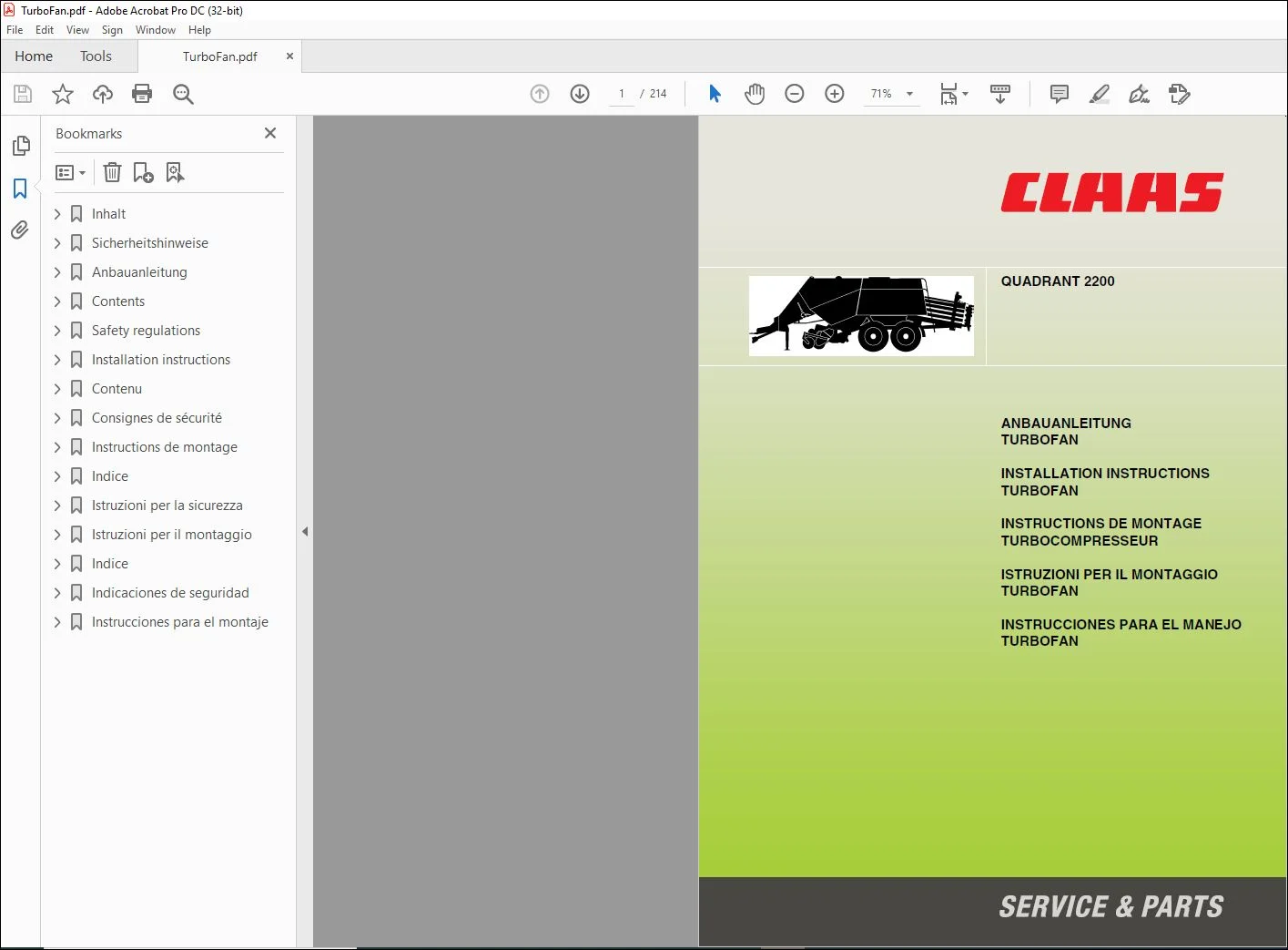
CLAAS Baler QUADRANT 2200 TURBOFAN INSTALLATION INSTRUCTIONS Manual_DE_EN_FR_IT_RU – PDF DOWNLOAD
Original price was: $78.00.$24.95Current price is: $24.95.
CLAAS Baler QUADRANT 2200 TURBOFAN INSTALLATION INSTRUCTIONS Manual_DE_EN_FR_IT_RU – PDF DOWNLOAD
Description
CLAAS Baler QUADRANT 2200 TURBOFAN INSTALLATION INSTRUCTIONS Manual_DE_EN_FR_IT_RU – PDF DOWNLOAD
DESCRIPTION:
CLAAS Baler QUADRANT 2200 TURBOFAN INSTALLATION INSTRUCTIONS Manual_DE_EN_FR_IT_RU – PDF DOWNLOAD
Besonders zu beachten
- Die Hinweise in dieser Anleitung müssen zur Abwendung von Gefahren von allen Personen gelesen und beachtet werden, die diese Maschine/Vorsatz einsetzen, warten, instand halten oder kontrollieren. Lesen Sie insbesondere den Abschnitt »Zur Sicherheit« aus Ihrer Betriebsanleitung und beachten Sie die gültigen Unfallverhütungsvorschriften Ihres Landes.
- Vor Beginn der Arbeiten feststellen, ob alle Werkzeuge und Hilfsmittel vorhanden sind. Einen Vergleich zwischen dem vorhandenen Maschinentyp/Vorsatztyp, der Aufstellung im Abschnitt »Lieferumfang« und des gelieferten Teilesatzes durchführen. Die Spezifikation der Teile, z.B. bei Schrauben, entnehmen Sie bitte der Auflistung “Lieferumfang”. In dieser
- Auflistung bekommt jedes Anbauteil eine Positionsnummer (Pos.-Nr.). Teile, wie z.B. Muttern und Contact-Scheiben, bekommen keine Positionsnummer. Diese Teile gehören zu der Positionsnummer der Schraube, mit der sie montiert werden. Weitere Angaben zu den Teilen sind die Ersatzteil-Nr., die Bezeichnung, die Abmessung, die DIN und die Anzahl.
- Bei den Montagebeschreibungen werden zur besseren Orientierung vorhandene Teile mit Buchstaben und Neuteile mit Zahlen (Positionsnummern) gekennzeichnet. Texte und Bilder sind nach Möglichkeit neutral gehalten. Auf Unterschiede zwischen den einzelnen Typen wird durch Texthinweise aufmerksam gemacht. Technische Angaben, Maße und Gewichte
- sind unverbindlich. Änderungen im Zuge der technischen Entwicklung und Irrtümer vorbehalten. Vorn, hinten, rechts und links gilt immer in Fahrtrichtung.
Allgemeine Sicherheits- und Unfallverhütungs- Vorschriften_DE
- Beachten Sie neben den Hinweisen in diesem Handbuch die allgemeinen Sicherheits- und Unfallverhütungs-Vorschriften.
- Tragen Sie bei Arbeiten mit der Presse enganliegende Kleidung. Weite Kleidung vermeiden!
- Zur Vermeidung von Brandgefahr Maschine sauber halten!
Important note
- In order to avoid any dangers all information in these instructions must be read and applied by all persons using, servicing, repairing or inspecting this machine/attachment. Especially the »SAFETY RULES« in this manual should be read with the utmost care and the accident prevention regulations of your country should be observed. Before starting the work, establish
- if all tools and equipment are at hand. Compare the machine type/attachment type at hand with the list in section»Delivery list« and the delivered spare parts set. The specifications of the parts, e.g. for bolts, can be found in the “Delivery list”. In this list, every mounting part has a position number (pos.-no.). Parts such as nuts and contact washers do not have a position
- number. These parts belong to the position number of the bolt with which they are mounted. Further data describing these parts are the spare part-no., the designation, the dimensions, the DIN and the quantity. In the installation instructions, the current parts are marked with letters and the new parts with numbers (position numbers) for easier orientation. Texts and
- pictures have been kept neutral whenever possible. Text references point out the differences between the individual types. Technical data, dimensions and weights are given as an indication only. Following the policy of CLAAS to improve their products as technical developments continue, CLAAS reserve the right to make alterations. Responsibility for errors or
- omissions not accepted. Front, rear, right hand and left hand always refer to the machine as seen in the direction of forward travel
General safety and accident prevention regulations_EN
- Besides the information in this manual you should also observe the general safety regulations and the instructions for the avoidance of accidents.
- Always wear light fitting clothes when working with the baler. Avoid baggy clothes!
- Prevent fire hazards by keeping the machine clean!
Important
- Cette notice doit être lue par toutes les personnes qui utilisent la machine/l’accessoire, qui s’occupent de la maintenance, de l’entretien ou du contrôle, afin d’éviter les accidents. Il est conseillé de porter une attention particulière au chapitre » Conseils de sécurité « de votre notice d’utilisation et de respecter les règles de prévention des accidents en vigueur dans
- votre pays. Avant de commencer les travaux, s’assurer que tous les outils et accessoires nécessaires sont préparés. Effectuer une comparaison entre le type de machine/d’accessoire existant, la liste figurant dans la section » Lot de pièces « et le kit de pièces fourni. La spécification des pièces, par exemple des vis, figure dans la liste » Lot de pièces «. Dans cette liste, chaque
- élément à monter est identifié par un numéro de position (no pos.). Les pièces telles que les écrous et les rondelles Contact ne sont pas identifiés par un numéro de position. Ces éléments font partie du numéro de position de la vis avec laquelle ils doivent être montés. D’autres indications données pour ces éléments sont le no de pièce de rechange, la désignation, les
- dimensions, la DIN et le nombre fourni. Dans les instructions de montage, les pièces existantes sont identifiées par des lettres et les nouvelles pièces par des chiffres (numéros de position) afin de permettre une meilleure orientation. Les textes et les illustrations sont neutres dans la mesure du possible. Les différences entre les différents types sont signalées par des notes dans le texte. Les indications relatives aux caractéristiques techniques, dimensions et poids sont fournies sans
- engagement. Sous toutes réserves d’erreurs et de modifications techniques dans le cadre du développement technique. Les termes avant, arrière, droite et gauche s’entendent toujours dans le sens d’avancement de la machine.
Consignes générales de sécurité et de
prévention des accidents_FR
- Outre les conseils contenus dans ce manuel d’utilisation, respecter également les règles générales de sécurité et de prévention des accidents.
- Porter des vêtements qui collent au corps lors de tout travail avec la presse. Eviter les vêtements amples !
- Toujours maintenir la machine en parfait état de propreté afin d’éviter tout risque d’incendie
TABLE OF CONTENTS:
CLAAS Baler QUADRANT 2200 TURBOFAN INSTALLATION INSTRUCTIONS Manual_DE_EN_FR_IT_RU – PDF DOWNLOAD
Inhalt
Inhalt 3
Sicherheitshinweise
Besonders zu beachten 7
Kennzeichnung von Warn- und Gefahrenhinweisen 8
Allgemeine Sicherheits- und Unfallverhütungs-Vorschriften 8
Verlassen der Maschine 8
Bestimmungsgemäße Verwendung 8
Anbauanleitung
Einleitung 11
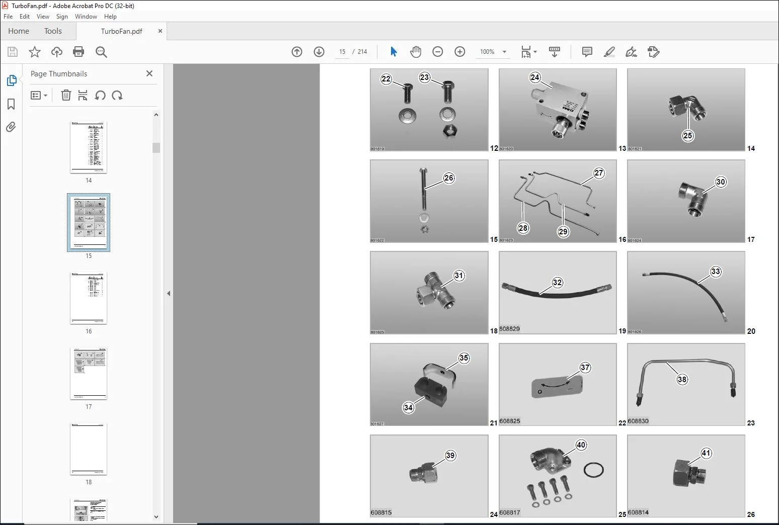
Teileumfang 12
Vorbereitung der Maschine 19
Maschinen mit Kompressor 19
Kompressor abbauen 19
Luftfilter abbauen 20
Druckluftleitung abbauen 21
Maschinen ohne Kompressor 21
Druckluftleitung abbauen 21
Oberen Druckluftbehälter und Spannbänder abbauen 22
Druckluftleitung mit Düsen abbauen 22
Einfachzahnradpumpe abbauen 24
Turbofan vormontieren 25
Hydraulische Vormontage des Behälters 25
Vormontage am Hydraulikölmotor 25
Druckausgang 25
Auslass 25
Turbofan anbauen 26
Doppelzahnradpumpe vormontieren und anbauen 26
Hydraulikölschläuche anbauen 27
Vordere Hydraulikölleitungen anbauen 27
Neue Hydraulikölschläuche anbauen 28
Obere Gelenkwelle abbauen 29
Querbleche und Getriebehalter abbauen 30
Turbogebläse anbauen 31
Ventil anbauen 33
Seitliche Hydraulikölleitungen anbauen 33
Gelenkwelle anbauen 36
Turbogebläseschutze anbauen 37
Hydrauliköltanks füllen 39
Behälter des hydraulischen Kreislaufs füllen 39
Getriebeöl auffüllen 40
Probelauf vorbereiten und durchführen 41
Contents
Contents 3
Safety regulations
Important note 7
Marking of warning and danger notes 8
General safety regulations and instructions for the
avoidance of accidents 8
Leaving the machine 8
Intended use 8
Installation instructions
Introduction 11
Scope of parts 12
Machine preparations 19
Machines with compressor 19
Removing the compressor 19
Remove the air filter 20
Remove air line 21
Machines without compressor 21
Remove air line 21
Remove the top compressed air reservoir and the
clamping belts 22
Remove air line with nozzles 22
Remove single gear pump 24
Pre-fitting turbofan 25
Hydraulic pre-fitting of tank 25
Pre-fitting on hydraulic oil motor 25
Pressure outlet 25
Port 25
Fitting turbofan 26
Pre-assemble and mount the duplex gear pump 26
Attach hydraulic oil hoses 27
Attach front hydraulic oil lines 27
Attach new hydraulic oil hoses 28
Remove the top propshaft 29
Remove the side guards and the gear bracket 30
Attach turbo blower 31
Attach valve 33
Attach hydraulic oil lines from the side 33
Assemble the propshaft 36
Fitting turbo fan guards 37
Fill hydraulic oil tanks 39
Filling hydraulic circuit tank 39
Top up gear oil 40
Prepare and perform a test run 41
Contenu
Contenu 3
Consignes de sécurité
Important 7
Caractérisation des indications sur les dangers 8
Consignes générales de sécurité et de prévention des
accidents 8
Stationnement de la machine 8
Utilisation conforme à la destination 8
Instructions de montage
Introduction 11
Lot de pièces (0841 7811) 12
Préparation de la machine 19
Machines avec compresseur 19
Démontage du compresseur 19
Dépose du filtre à air 20
Dépose de la conduite pneumatique 21
Machines sans compresseur 21
Dépose de la conduite pneumatique 21
Dépose du réservoir d’air comprimé supérieur et
des sangles de serrage 22
Dépose de la conduite pneumatique avec les buses 22
Dépose de la pompe à engrenage simple 24
Prémontage de la turbofan 25
Prémontage hydraulique du réservoir 25
Prémontage au niveau du moteur hydraulique 25
Sortie de pression 25
Sortie 25
Montage de la turbofan 26
Prémontage et montage de la pompe à engrenage double 26
Montage des flexibles hydrauliques 27
Montage des conduites hydrauliques avant 27
Montage des nouveaux flexibles hydrauliques 28
Dépose de l’arbre à cardan supérieur 29
Dépose des tôles transversales et des supports de boîte 30
Montage de la Turbofan 31
Montage du bloc hydraulique 33
Montage des conduites hydrauliques latérales 33
Montage de l’arbre à cardan 36
Montage des tôles de protection de la Turbofan 37
Remplissage du réservoir d’huile hydraulique
de la Turbofan 39
Remplissage du réservoir du circuit hydraulique 39
Remise à niveau de l’huile de transmission 40
Test de fonctionnement 41
Indice
Indice 3
Istruzioni per la sicurezza
Avvertenze importanti 7
Contrassegno degli avvisi di avvertimento e di pericolo 8
Norme di sicurezza e antinfortunistiche generali 8
Lasciare la macchina 8
Uso conforme alla destinazione 8
Istruzioni per il montaggio
Introduzione 11
Entità dei pezzi 12
Preparazione della macchina 19
Macchine con compressore 19
Smontaggio del compressore 19
Smontaggio del filtro dell’aria 20
Smontaggio della conduttura di aria compressa 21
Macchine senza compressore 21
Smontaggio della conduttura di aria compressa 21
Smontaggio del serbatoio dell’aria compressa in alto e
dei nastri di serraggio 22
Smontaggio della conduttura di aria compressa con ugelli 22
Smontaggio della pompa ad ingranaggi semplici 24
Premontare il Turbofan 25
Premontaggio idraulico del serbatoio 25
Premontaggio nel motore idraulico 25
Uscita pressione 25
Uscita 25
Montare il Turbofan 26
Premontaggio e montaggio della pompa ad ingranaggi
doppi 26
Montare i tubi flessibili idraulici 27
Montaggio delle tubazioni idrauliche anteriori 27
Montaggio di nuovi tubi flessibili idraulici 28
Smontaggio dell’albero snodato superiore 29
Smontaggio delle lamiere trasversali e del supporto
del meccanismo 30
Montaggio del turboventilatore 31
Montaggio della valvola 33
Montaggio delle tubazioni idrauliche laterali 33
Montaggio dell’albero a snodo 36
Montare il raccordo del turboventilatore 37
Rabbocco dei serbatoi idraulici 39
Riempire il serbatoio del circuito idraulico 39
Rabbocco olio per meccanismi 40
Preparazione ed esecuzione di una prova
di funzionamento 41
Indice
Indice 3
Indicaciones de seguridad
Nota importante 7
Caracterización de indicaciones de aviso y de peligro 8
Normas generales relativas a la seguridad y a la
prevención de accidentes 8
Abandonar la máquina 8
Uso adecuado de la máquina 8
Instrucciones para el montaje
Introducción 11
Cantidad de piezas 12
Preparación de la máquina 19
Máquinas con compresor 19
Desmontar el compresor 19
Desmontar el filtro de aire 20
Desmontar la tubería del aire comprimido 21
Máquinas sin compresor 21
Desmontar la tubería del aire comprimido 21
Desmontar el depósito del aire a presión superior y
las cintas de sujeción 22
Desmontar la tubería del aire comprimido junto con
las toberas 22
Desmontar la bomba simple de engranajes 24
Premontaje del Turbofan 25
Premontaje hidráulico del depósito 25
Premontaje en el motor de aceite hidráulico 25
Salida de presión 25
Salida 25
Montar el Turbofan 26
Premontar la bomba de ruedas dentadas dúplex
y montarla 26
Montar las mangueras para el aceite hidráulico 27
Montar las tuberías delanteras para el aceite hidráulico 27
Montar las mangueras nuevas para el aceite hidráulico 28
Desmontar el árbol de transmisión superior 29
Desmontar las chapas transversales y el
soporte del accionamiento 30
Montar el turbosoplador 31
Montar la válvula 33
Montar las tuberías laterales para el aceite hidráulico 33
Montar el árbol de transmisión 36
Montaje de las protecciones del turbosoplador 37
Llenar los depósitos de aceite hidráulico 39
Llenar el depósito del circuito hidráulico 39
Repostar aceite para engranajes 40
Preparar y efectuar una prueba de funcionamiento 41
IMAGES PREVIEW OF THE MANUAL:
PLEASE NOTE:
- This is the same manual used by the DEALERSHIPS to SERVICE your vehicle.
- The manual can be all yours – Once payment is complete, you will be taken to the download page from where you can download the manual. All in 2-5 minutes time!!
- Need any other service / repair / parts manual, please feel free to contact us at heydownloadss @gmail.com . We may surprise you with a nice offer
S.M