Claas Conspeed 8-7570 Lineat Conspeed 6-7570 Linear Repair Manual – PDF DOWNLOAD
IMAGES PREVIEW OF THE MANUAL:
Claas Conspeed 8-7570 Lineat Conspeed 6-7570 Linear Repair Manual – PDF DOWNLOADClaas Conspeed 8-7570 Lineat Conspeed 6-7570 Linear Repair Manual – PDF DOWNLOAD
DESCRIPTION:
Claas Conspeed 8-7570 Lineat Conspeed 6-7570 Linear Repair Manual – PDF DOWNLOAD
General Information
How to use the Manual :
The present Repair Manual is to assist in maintaining permanent machine availability. The high value of the harvesting machine is ensured through careful maintenance and technical monitoring by customer service. Experience gathered by both our service engineers and factory staff has been compiled in this Repair Manual.
The sequence of pictures shows the procedure of a repair. The text provides the necessary information about the adjustments to be made, the use of special tools etc. Essential repairs are listed in such a way that even individual and small repairs can be easily found and followed.
Supplements are added to reflect the ongoing technical development of the machines and the manual is thereby continuously being updated as a reference book. As a precaution, always compare the setting values and fill quantities with the most recent operator’s manual for the respective machine.
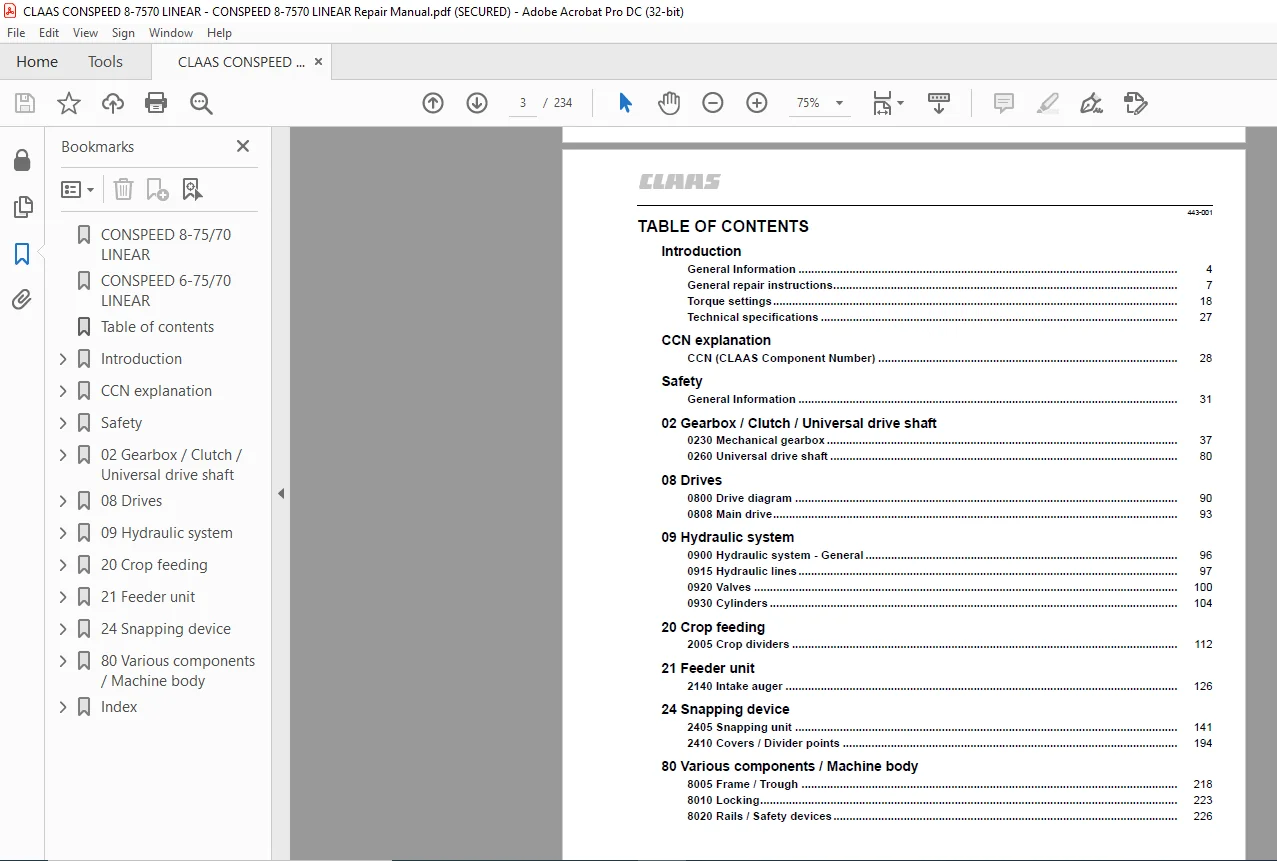
TABLE OF CONTENTS:
Claas Conspeed 8-7570 Lineat Conspeed 6-7570 Linear Repair Manual – PDF DOWNLOAD
CONSPEED 8-75/70 LINEAR............................................................................................................. 1
CONSPEED 6-75/70 LINEAR............................................................................................................. 1
Table of contents................................................................................................................... 3
Introduction........................................................................................................................ 4
General Information............................................................................................................. 4
How to use the Manual....................................................................................................... 4
Validity of manual.......................................................................................................... 6
General repair instructions..................................................................................................... 7
Technical data.............................................................................................................. 7
Reason of damage............................................................................................................ 7
Spare parts................................................................................................................. 7
Diesel engine............................................................................................................... 7
Gearboxes................................................................................................................... 7
Alternator.................................................................................................................. 8
Welding Work................................................................................................................ 8
Drive belt / drive chain.................................................................................................... 8
Steel roller chains......................................................................................................... 9
Tensioning.............................................................................................................. 9
Chain connector......................................................................................................... 9
Taper ring fasteners........................................................................................................ 9
Gib head key fastenings..................................................................................................... 10
Self-locking bolts with micro-encapsulated glue............................................................................. 10
Liquid locking compound..................................................................................................... 11
Lock collar bearing......................................................................................................... 11
Adapter sleeve bearing...................................................................................................... 12
Ferrule fittings on hydraulic lines......................................................................................... 12
Progressive ring fittings on hydraulic lines................................................................................ 13
Sealing cone on hydraulic lines............................................................................................. 14
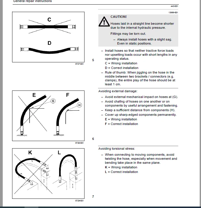
Hydraulic hoses............................................................................................................. 14
Notes on economical repair.................................................................................................. 17
Torque settings................................................................................................................. 18
Tightening torques for metric standard threads.............................................................................. 18
Tightening torque for metric fine threads................................................................................... 18
Tightening torques for hydraulic screw fittings with ferrule DIN 3861....................................................... 19
Tightening torques for hydraulic screw fittings and air conditioner screw fittings with O-ring and sealing cone DIN 3865.... 20
Tightening torques for hydraulic male connectors DIN 3901................................................................... 21
Tightening torques for direction-adjustable hydraulic male connectors ISO 6149-2 / ISO 11926-2 (3).......................... 22
Tightening torques for hydraulic swing fittings............................................................................. 23
Tightening torques for hollow screws DIN 7643............................................................................... 24
Tightening torques for brake line screw fittings............................................................................ 24
Tightening torques for worm-type threaded clips............................................................................. 25
Tightening torques for spring-loaded worm drive clamps...................................................................... 26
Tightening torques for tyres................................................................................................ 26
Technical specifications........................................................................................................ 27
Lubricants.................................................................................................................. 27
CCN explanation..................................................................................................................... 28
CCN (CLAAS Component Number).................................................................................................... 28
General..................................................................................................................... 28
Electric system standard.................................................................................................... 28
Overview................................................................................................................ 28
Hydraulic system standard................................................................................................... 28
Overview................................................................................................................ 29
CCN Index................................................................................................................... 30
2....................................................................................................................... 30
3....................................................................................................................... 30
7....................................................................................................................... 30
8....................................................................................................................... 30
B....................................................................................................................... 30
M....................................................................................................................... 30
Y....................................................................................................................... 30
Safety.............................................................................................................................. 31
General Information............................................................................................................. 31
Important note.............................................................................................................. 31
Identification of warning and danger signs.................................................................................. 31
General Safety and Accident Prevention Regulations.......................................................................... 32
Leaving the machine......................................................................................................... 33
Adjusting and maintenance work.............................................................................................. 33
Risk of injury through hydraulic liquid..................................................................................... 34
Air conditioner............................................................................................................. 34
Hydraulic accumulators...................................................................................................... 35
First aid measures.......................................................................................................... 35
Battery isolating switch.................................................................................................... 35
Jacking up the machine...................................................................................................... 36
Putting the machine out of operation........................................................................................ 36
02 Gearbox / Clutch / Universal drive shaft......................................................................................... 37
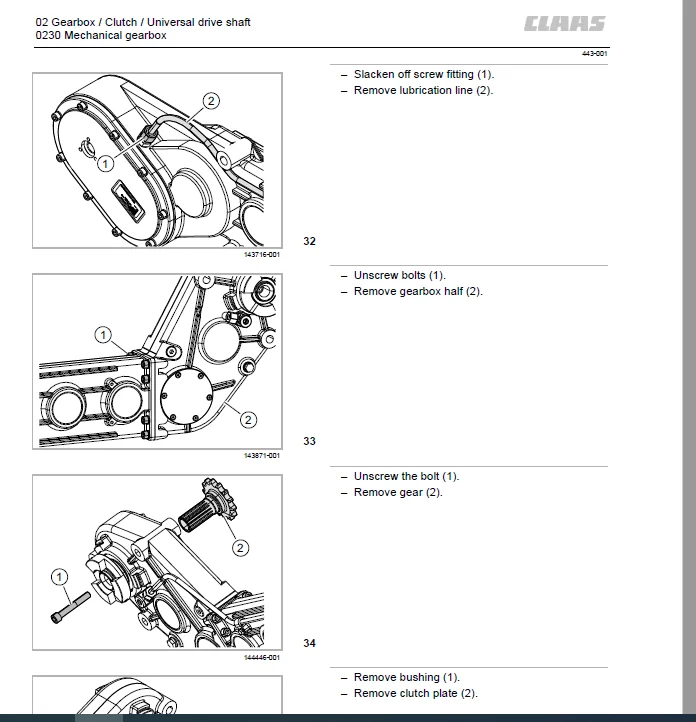
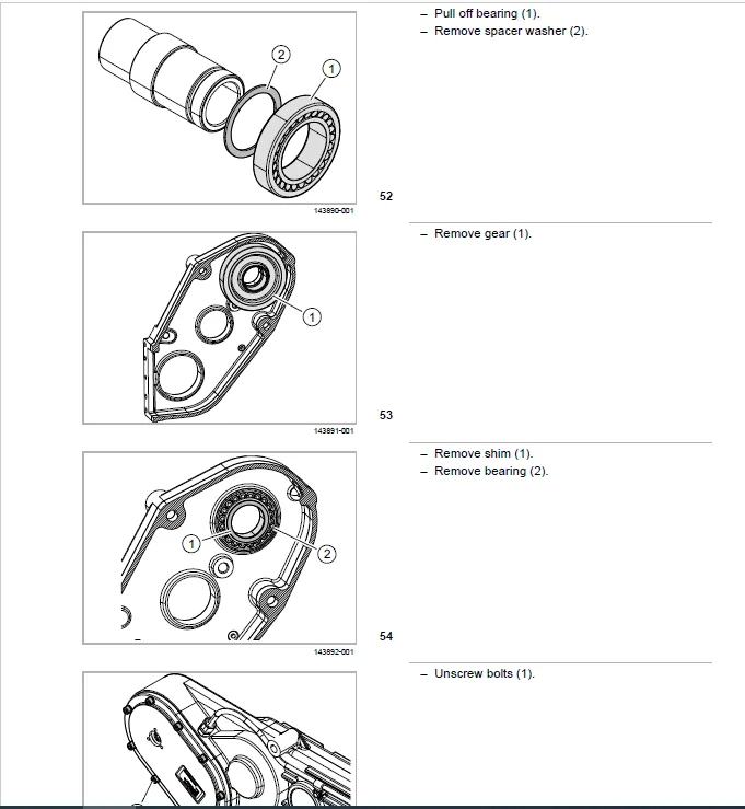
0230 Mechanical gearbox......................................................................................................... 37
Main transmission........................................................................................................... 38
Work preparation........................................................................................................ 39
Special tool............................................................................................................ 39
Removal with rigid front attachment..................................................................................... 40
Removal with folding front attachment................................................................................... 43
Disassembly............................................................................................................. 45
Assembly................................................................................................................ 59
Installation with folding front attachment.............................................................................. 75
Installation with rigid front attachment................................................................................ 77
0260 Universal drive shaft...................................................................................................... 80
Universal drive shaft....................................................................................................... 81
Work preparation........................................................................................................ 82
Disassembly............................................................................................................. 82
Assembly................................................................................................................ 86
08 Drives........................................................................................................................... 90
0800 Drive diagram.............................................................................................................. 90
Drive diagram............................................................................................................... 91
0808 Main drive................................................................................................................. 93
Drive mechanism............................................................................................................. 94
Work preparation........................................................................................................ 95
09 Hydraulic system................................................................................................................. 96
0900 Hydraulic system - General................................................................................................. 96
Damage to the hydraulic system.............................................................................................. 96
0915 Hydraulic lines............................................................................................................ 97
Multi-coupling.............................................................................................................. 98
0920 Valves.....................................................................................................................100
Valve block, general........................................................................................................100
Special tool............................................................................................................100
Main valve block............................................................................................................101
Installation instructions...............................................................................................103
0930 Cylinders..................................................................................................................104
Swinging hydraulic cylinder (3027)..........................................................................................105
Work preparation........................................................................................................106
Removal.................................................................................................................106
Installation............................................................................................................108
Bleeding................................................................................................................109
Locking the picker hydraulic cylinder.......................................................................................110
Work preparation........................................................................................................111
Installation instructions...............................................................................................111
20 Crop feeding.....................................................................................................................112
2005 Crop dividers..............................................................................................................112
Down maize auger............................................................................................................113
Work preparation........................................................................................................114
Removal.................................................................................................................114
Disassembly.............................................................................................................115
Assembly................................................................................................................116
Installation............................................................................................................117
Down maize auger bearing....................................................................................................119
Removal.................................................................................................................120
Installation............................................................................................................120
Down maize auger hydraulic motor (2040).....................................................................................121
Work preparation........................................................................................................122
Removal.................................................................................................................122
Installation............................................................................................................124
21 Feeder unit......................................................................................................................126
2140 Intake auger...............................................................................................................126
Feed roller, folding........................................................................................................127
Work preparation........................................................................................................128
Special tool............................................................................................................130
Installation instructions...............................................................................................134
Rigid feed roller...........................................................................................................136
Work preparation........................................................................................................137
Special tool............................................................................................................137
Installation instructions...............................................................................................138
Feed roller drive...........................................................................................................139
Work preparation........................................................................................................140
24 Snapping device..................................................................................................................141
2405 Snapping unit..............................................................................................................141
Snapping unit...............................................................................................................142
Snapping plate adjustment sensor (B055).....................................................................................144
Frame.......................................................................................................................146
Work preparation........................................................................................................147
Snapping plates.............................................................................................................148
Removal.................................................................................................................149
Installation............................................................................................................150
Snapping plate adjustment...................................................................................................152
Work preparation........................................................................................................153
Removal.................................................................................................................153
Installation............................................................................................................156
Scraper plates..............................................................................................................160
Work preparation........................................................................................................161
Installation instructions...............................................................................................161
Snapping rollers............................................................................................................162
Work preparation........................................................................................................163
Removal.................................................................................................................163
Disassembly.............................................................................................................164
Assembly................................................................................................................166
Installation............................................................................................................167
Snapping chains.............................................................................................................168
Work preparation........................................................................................................169
Removal.................................................................................................................169
Installation............................................................................................................172
Chopper.....................................................................................................................175
Work preparation........................................................................................................176
Picker gearbox..............................................................................................................177
Work preparation........................................................................................................181
Special tool............................................................................................................181
Removal.................................................................................................................181
Disassembly.............................................................................................................184
Assembly................................................................................................................186
Installation............................................................................................................187
Snapping plate adjustment hydraulic cylinder (3030).........................................................................191
Work preparation........................................................................................................192
Installation instructions...............................................................................................192
Venting.................................................................................................................193
2410 Covers / Divider points....................................................................................................194
Outer covers, divider points................................................................................................195
Work preparation........................................................................................................196
Removing the divider points.............................................................................................196
Removing the covers.....................................................................................................196
Removing the frame......................................................................................................198
Fitting the frame.......................................................................................................201
Installing the covers...................................................................................................204
Installing the divider points...........................................................................................205
Outer covers, divider points................................................................................................206
Work preparation........................................................................................................208
Removing the divider points.............................................................................................208
Removing the covers.....................................................................................................209
Removing the support....................................................................................................209
Removing the frame......................................................................................................209
Fitting the frame.......................................................................................................211
Installing the support..................................................................................................212
Installing the covers...................................................................................................212
Installing the divider points...........................................................................................213
Hydraulic cylinder of covers (3029).........................................................................................214
Work preparation........................................................................................................215
Installation instructions...............................................................................................215
Adjustment..............................................................................................................216
Venting.................................................................................................................216
80 Various components / Machine body................................................................................................218
8005 Frame / Trough.............................................................................................................218
Swinging kinematics.........................................................................................................219
Work preparation........................................................................................................220
Stubble breaker.............................................................................................................221
Work preparation........................................................................................................222
8010 Locking....................................................................................................................223
Locking.....................................................................................................................224
8020 Rails / Safety devices.....................................................................................................226
Lower guard.................................................................................................................227
Work preparation........................................................................................................228
Index...............................................................................................................................229
A...............................................................................................................................229
C...............................................................................................................................229
D...............................................................................................................................229
E...............................................................................................................................229
F...............................................................................................................................229
H...............................................................................................................................229
I...............................................................................................................................229
J...............................................................................................................................229
L...............................................................................................................................229
M...............................................................................................................................229
P...............................................................................................................................230
R...............................................................................................................................230
S...............................................................................................................................230
T...............................................................................................................................230
U...............................................................................................................................231
V...............................................................................................................................231
W...............................................................................................................................231
CLAAS CONSPEED 8-7570 LINEAT CONSPEED 6-7570 LINEAR REPAIR MANUAL – PDF DOWNLOAD:
PLEASE NOTE:
This is not a physical manual but a digital manual – meaning no physical copy will be couriered to you. The manual can be yours in the next 2 mins as once you make the payment, you will be directed to the download page IMMEDIATELY.
This is the same manual used by the dealers inorder to diagnose your vehicle of its faults.
Require some other service manual or have any queries: please WRITE to us at [email protected]
S.V
✹
What Our Customers Say
★★★★★Live reviews from customers
Loading customer reviews...
🌟 Related Products
Discover more professional manuals for your equipment