CLAAS COUGAR 1400 Operator’s Manual – PDF DOWNLOAD
Original price was: $89.95.$28.95Current price is: $28.95.
CLAAS COUGAR 1400 Operator’s Manual – PDF DOWNLOAD
VALIDITY
This operating instruction is valid for all self-propelled
mower units:
COUGAR 1400:
Basic machine:
Type 789
from serial number 789 0 1001
Mower unit
Type 788
from serial number 788 0 1001.
Description
CLAAS COUGAR 1400 Operator’s Manual – PDF DOWNLOAD
DESCRIPTION:
CLAAS COUGAR 1400 Operator’s Manual – PDF DOWNLOAD
INTRODUCTION:
This manual is intended primarily for the machine operator and provides information on the use, adjustment, operation and maintenance of the self-propelled mower unit COUGAR. Follow the advice on maintenance and service for your machine in order to obtain maximum performance and long service from your COUGAR. The regular inspections of your machine should be carried out by your CLAAS specialist workshop. Neglect in maintenance or service, and incorrect operation will result in poor machine efficiency and loss of valuable time. With correct operation and maintenance, your machine will always give reliable service.
ROAD TRAVEL In other countries, different traffic regulations may apply. In the event of variations from the data from the manufacturer, the regulations of the country concerned always take precedence. Apart from his driving license, the operator must always have the Vehicle Type Approval supplied by the manufacturer, a warning triangle, and at least 2 wheel chocks. When travelling on public roads with the self-propelled mower unit, all specifications and constraints mentioned in the copy of the Vehicle Type Approval (§ 18 Fig. 5 StVZO) or in the vehicle’s registration documents must be observed.
VALIDITY
This operating instruction is valid for all self-propelled
mower units:
COUGAR 1400:
Basic machine:
Type 789
from serial number 789 0 1001
Mower unit
Type 788
from serial number 788 0 1001.
TABLE OF CONTENTS:
CLAAS COUGAR 1400 Operator’s Manual – PDF DOWNLOAD
1 Machine overview
Machine overview 1 1 1
2 Introduction
Introduction 2 1 1
Validity 2 1 1
3 Table of contents
Table of contents 3 1 1
4 General information
Road travel 4 1 1
Of special importance 4 2 1
Identification Plate/serial Number 4 3 1
Identification plate/machine number 4 3 2
Engine serial number 4 3 2
Transmission identification plate 4 3 2
Axle identification plate 4 3 3
Identification plate of telescopic outrigger on mower unit,
centre left 4 3 3
Identification plate of telescopic outrigger on mower unit,
centre right 4 3 3
Identification plate of mower units, centre left/right and
front centre 4 3 4
Identification plate of mower unit, front left 4 3 4
Identification plate of mower unit, front right 4 3 4
Identification plate of hitch frame, mower unit front 4 3 5
5 Safety rules
Safety rules 5 1 1
Wheel chocks 5 1 7
Applying the wheel chocks 5 1 7
Battery isolator switch 5 1 8
Safety decals with pictorials 5 2 1
6 Specifications
CLAAS Cougar 1400 6 1 1
Engine 6 1 1
Ground drive 6 1 1
Steering 6 1 1
Brakes 6 1 1
Tyres and air pressures 6 1 2
Hydraulic system 6 1 2
PTO drives 6 1 2
Tightening torque 6 1 2
Mower units 6 1 3
Dimensions 6 1 3
7 Prior to operation Basic machine
Cabin 7 1 1
Roof console – overview 7 1 1
Air conditioner 7 1 3
Operating and display elements 7 1 3
Putting the air conditioner into operation 7 1 4
Adjusting the cabin temperature 7 1 5
Manually setting the evaporator fan speed 7 1 5
Activating ECON mode 7 1 6
Deactivating ECON mode 7 1 6
REHEAT operation
(demisting cabin windows) 7 1 7
Displaying the outside temperature 7 1 8
Changing the temperature display to ° Fahrenheit 7 1 8
Heating the leg area 7 1 8
Temperature sensor F0 fault indicator (cabin, blue) 7 1 9
Temperature sensor F1 fault indicator (outlet, yellow) 7 1 9
Temperature sensor F2 fault indicator (outside, red) 7 1 9
Mirror 7 1 10
Coarse mirror adjustment 7 1 10
Fine mirror adjustment 7 1 10
Turning on the mirror heating 7 1 10
Adjusting the lighting 7 1 11
Driving lights 7 1 11
Working lights 7 1 12
Roll-up sun blinds 7 1 12
Sun blinds front/back 7 1 12
Side sun blinds 7 1 13
Opening and closing the cabin roof 7 1 13
Switch console 7 1 14
Adjusting the operator’s seat 7 1 15
Adjusting the steering column 7 1 18
Swing the steering column downwards 7 1 18
Swinging the steering column upwards 7 1 18
Adjusting the steering wheel height 7 1 18
Vehicle information unit 7 1 19
Multi-function switch 7 1 19
Multifunction handle 7 1 20
Windscreen washer 7 1 21
Tyres 7 2 1
Mudguards on the mower unit axle 7 2 1
8 Prior to operation Mower units
Check and observe the following
before putting into operation 8 1 1
Attaching front mower unit 8 1 2
Prop stands 8 1 4
Unhitching and parking front mower unit 8 1 5
Fitting the mower blades 8 1 6
Additional equipment – mower unit 8 1 7
Warning beacon 8 1 7
Additional clearance lights 8 1 7
9 Operation Basic machine
Driving the Cougar 9 1 1
Starting the engine 9 1 1
Starting to drive 9 1 2
Select the gear 9 1 2
Adjusting the engine speed 9 1 3
Using the ground speed control lever 9 1 4
Engaging/disengaging the differential locks 9 1 5
Engaging the automatic differential lock 9 1 5
Manual engagement of the differential lock 9 1 5
Stopping 9 1 6
Stopping with the ground speed control lever 9 1 6
Table of contents
3 1 2 BA COUGAR 1400 – 0293 140 1
Table of contents
Stopping with the foot brake 9 1 6
Brakes 9 1 7
Foot brake 9 1 7
Parking brake 9 1 7
Parking the vehicle 9 1 8
Towing the vehicle 9 1 9
Rotating the driver’s cabin 9 1 10
Recirculation ventilator 9 1 12
Manual activation of recirculation fan 9 1 12
10 Operation Mower units
Overview of controls 10 1 1
Switch console 10 1 2
Multifunction handle 10 1 3
Changeover switch M16 10 1 4
Automatic function 10 1 4
Semi-automatic function 10 1 5
Sequence control 10 1 6
Manual operation 10 1 6
Example “Semi-automatic function” 10 1 6
Example “Manual operation” 10 1 9
Functions 10 2 1
Working position 10 2 1
Carrier system 10 2 4
Mower unit drive 10 2 5
Collision protection 10 2 6
Headland position 10 2 8
Folded position 10 2 10
Mower unit floating 10 2 10
Working width of mower unit 10 2 12
Mowing 10 2 14
Instructions for mowing 10 2 15
Working with single mower units 10 2 17
Recommendation for environmental protection 10 2 18
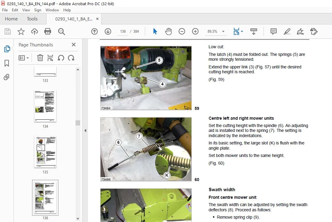
Cutting height 10 2 20
Swath width 10 2 22
Conditioner 10 2 24
Transport position 10 2 25
Emergency control 10 2 28
11 Operation CEBIS
CLAAS CEBIS on-board information system 11 1 1
CEBIS monitor and rotary switch 11 1 2
Keypad C 11 1 2
Rotary switch D 11 1 2
Multi-function controller M 11 1 2
Screen areas E
(Road view) 11 1 3
Screen areas E
(Work view) 11 1 4
Navigation 11 1 5
Status display – mower units 11 1 6
“Settings” Menu 11 2 1
CLAAS data set 11 2 1
Custom settings 11 2 1
Current data set 11 2 1
Calling up the “Settings” menu 11 2 2
Display settings 11 2 3
Loading settings 11 2 4
Changing settings 11 2 5
Storing the settings 11 2 6
“Vehicle” menu 11 3 1
Calling up the “Vehicle” menu 11 3 2
Setting the working speed 11 3 3
Setting the working speed directly 11 3 4
Programming the reversing ventilator 11 3 5
Setting the type of actuation for the reversing ventilator 11 3 6
Setting the reversing interval 11 3 7
Setting the duration of the ventilator reversal 11 3 8
Setting the transmission mode 11 3 9
Setting the steering 11 3 10
Steering programs 11 3 10
Standard steering mode 11 3 10
All-wheel steering 11 3 10
Parallel steer mode 11 3 11
Activating a steering program 11 3 12
Calling up the “Steering” menu 11 3 12
Calling up the “Steering mode” menu 11 3 13
Changing the steering program 11 3 14
Calling up the “Parallel steer mode setting” menu 11 3 15
Maximum parallel steer mode steering angle 11 3 15
Straight ahead travel ON/OFF 11 3 17
Displaying the driving information 11 3 18
“Driving information” menu 11 4 1
Displaying the driving information 11 4 1
“Ground pressure” menu 11 5 1
Calling up the “Ground pressure” menu 11 5 1
Setting the relief set value 11 5 2
Setting the relief directly 11 5 4
Display of relief in the working view 11 5 5
“Overlap” menu 11 6 1
Calling up the “Overlap” menu 11 6 1
Setting the overlap set value 11 6 2
Setting overlap for straight line travel/curve travel 11 6 2
Setting the connection overlap 11 6 3
Directly setting the overlap for straight ahead travel 11 6 4
Overlap display in the working view 11 6 5
“Headland” menu 11 7 1
Calling up the “Headland” menu 11 7 1
Setting the headland heights 11 7 2
Speed dependent delay 11 7 3
Time dependent delay 11 7 3
Changing over the headland strategy 11 7 5
Changing the headland settings 11 7 5
“Lifting unit” menu 11 8 1
Call up the “Lifting unit” menu 11 8 1
Setting the lifting unit 11 8 2
Setting the lower link 11 8 2
Setting the upper link 11 8 3
“Maintenance” menu 11 9 1
Call up the “Maintenance” menu 11 9 1
“CEBIS” menu 11 9 2
Call up the “CEBIS” menu 11 9 2
“Monitor contrast” menu 11 9 3
Directly setting the monitor contrast 11 9 3
“Resetting the adjustments” menu 11 9 4
“Joystick” menu 11 9 4
0293 140 1 – BA COUGAR 1400 3 1 3
Table of contents
“On-board Diagnostics” menu 11 9 5
“Emergency adjustment”- mower units 11 9 6
Calling up “Emergency adjustment” menu 11 9 6
“Limit stops” menu 11 9 8
Calling up the “Limit stops learning” menu 11 9 8
“End stops” menu – Mower unit 11 9 9
“Impulses per 100 m learning” menu 11 9 10
“Limit stops” menu – ground speed control
lever/hydrostat 11 9 11
CEBIS “Settings” menu 11 9 13
Calling up the “Settings” menu 11 9 13
“Units” menu 11 9 14
“Language” menu 11 9 15
“Time/date setting” menu 11 9 15
“Monitoring” menu 11 9 16
“Counter” menu 11 9 17
Calling up the “Counter” menu 11 9 18
Resetting the “Day” counter menu 11 9 18
Faults and remedies 11 10 1
Fault signal/long alarm signal 11 10 2
Warning message/three alarm signals 11 10 3
Info message/single alarm signal 11 10 3
Fault code table 11 10 4
12 Maintenance Basic machine
Important Maintenance Instructions 12 1 1
Important maintenance instructions and safety rules 12 1 1
Maintenance schedules and lubricants charts 12 2 1
Maintenance schedule 12 2 1
Lubricants chart 12 2 3
Opening the guard covers 12 3 1
Opening the lower lower engine hood 12 3 1
Opening the upper engine hood 12 3 1
Opening the vehicle hood 12 3 1
Hydraulic system 12 4 1
Pressure accumulator 12 4 1
Checking the hydraulic oil level 12 4 1
Changing the hydraulic oil 12 4 1
Replacing the hydraulic oil filter in the
working hydraulics 12 4 2
Replacing the hydraulic oil filter in the road drive 12 4 2
Replacing the suction filter 12 4 3
Replacing the venting filter 12 4 3
Topping up hydraulic oil 12 4 4
Gearbox 12 5 1
Drive gearbox 12 5 1
Checking transmission oil level 12 5 1
Changing the transmission oil 12 5 1
Topping up transmission oil 12 5 2
Transfer gearbox engine take-off 12 5 3
Check oil level in transfer gearbox 12 5 3
Changing the oil in transfer gearbox 12 5 3
Topping up the oil in transfer gearbox 12 5 3
Transfer gearbox mower units 12 5 4
Check oil level in transfer gearbox 12 5 4
Changing the oil in transfer gearbox 12 5 4
Topping up the oil in transfer gearbox 12 5 4
PTO gearbox 12 5 5
Checking the PTO gearbox oil level 12 5 5
Changing the PTO gearbox oil 12 5 5
Topping up PTO gearbox oil 12 5 5
Axles 12 6 1
Check planetary gear oil level 12 6 1
Changing the planetary gear oil 12 6 1
Check differential oil level 12 6 2
Changing the differential oil 12 6 3
Air conditioner 12 7 1
Checking/cleaning the condenser 12 7 1
Checking the refrigerant level 12 7 1
Checking the moisture saturation of the filter
receiver drier 12 7 2
Cabin 12 8 1
Cleaning/replacing the cabin filters 12 8 1
Cleaning the units located in the cabin roof 12 8 1
Checking the windscreen washer 12 8 2
Compressed air system/brakes 12 9 1
Compressed air connection point 12 9 1
Take care when removing air 12 9 1
Checking/tightening the retaining straps 12 9 2
Check/clean the water drain valve 12 9 2
Checking the pressure regulator 12 9 2
Checking the safety valve 12 9 3
Releasing the parking brake 12 9 4
Drive belts of mower unit centre left/right 12 10 1
Removing the drive belts 12 10 1
Fitting and tensioning the drive belts 12 10 2
Recommendations for winter storage 12 11 1
13 Maintenance Mower units
Important maintenance instructions 13 1 1
Hydraulic system 13 1 1
Energy-storage mechanisms/springs 13 1 1
Bolts 13 1 1
Lubrication 13 1 1
Guards (safety frames) 13 1 1
Maintenance and lubrication charts 13 2 1
Maintenance schedules 13 2 1
Lubricants chart 13 2 3
Drive layout 13 3 1
Drive Systems 13 4 1
Gearboxes 13 4 1
Main gearbox in hitch frame 13 4 1
Main gearbox of front centre mower unit 13 4 2
Gearbox of front left and right mower unit 13 4 3
Side gearbox of front centre mower unit,
centre left and right 13 4 3
Main gearbox of centre left and right mower unit 13 4 4
Drive train of mower unit left/right 13 4 5
V-belts 13 4 6
Checking V-belts 13 4 6
Tensioning the conditioner drive belts 13 4 6
Mower head 13 4 8
Mower blades 13 4 10
Mower blade box 13 4 11
Changing the mower blades 13 4 12
Quick-change system for mower blades 13 4 13
Mower blade mounting studs
(mower blade quick change system) 13 4 16
3 1 4 BA COUGAR 1400 – 0293 140 1
Table of contents
Bolted mower blades 13 4 18
Mower blade fixing
(bolted version) 13 4 19
Cutting discs 13 4 21
Replacing cutting discs 13 4 21
Conditioning tines 13 4 23
Installing and removing tines 13 4 23
Spring adjustment 13 4 24
Adapting front centre mower unit to ground contour 13 4 24
Adapting centre left and right mower unit to
ground contour 13 4 24
Restricting adaptation of centre left and right
mower unit to ground contour 13 4 25
Telescopic arm 13 4 26
Adjusting the play 13 4 26
Lubricating the telescopic arms 13 4 27
Electrical 13 4 27
Speed sensor 13 4 27
Angle sensor on centre left and right mower
unit swing arm 13 4 29
Angle sensor of lifting unit 13 4 30
Clutches 13 4 31
Drive shaft 13 4 31
General information on universal drive shafts 13 4 32
Removing and mounting drive shaft guard 13 4 32
Hydraulic system 13 4 35
Hydraulic hoses 13 4 35
Pressure accumulator 13 4 35
Hydraulic cylinder with vacuum valve 13 4 36
Lubrication holes 13 4 36
Screw connections 13 4 36
Connecting elements 13 4 36
End of season storage 13 4 37
14 Maintenance Engine
Important maintenance instructions 14 1 1
Important maintenance instructions and safety rules 14 1 1
Maintenance and lubricants chart 14 2 1
Maintenance schedule 14 2 1
Lubricants chart 14 2 2
Engine Overview 14 3 1
Fuel system – engine oil – V- belts 14 4 1
Fuel System 14 4 1
Fuel tank 14 4 1
Manual fuel pump with fuel pre-cleaner 14 4 2
Fuel filter 14 4 2
Checking the water separator/draining water 14 4 2
Replacing the fuel pre-filter cartridge 14 4 3
Venting the fuel system 14 4 3
Engine oil level check 14 4 4
Changing the engine oil 14 4 5
Changing the oil filter 14 4 6
Change breather filter 14 4 6
Top up engine oil 14 4 7
Ventilator and three-phase alternator drive belts 14 4 7
Checking the drive belt condition 14 4 7
Checking the screwed connections 14 4 7
Cooling system 14 5 1
Coolant 14 5 1
Draining the coolant 14 5 1
Topping up coolant 14 5 2
Over-pressure 14 5 3
Coolant temperature 14 5 3
Clean the water cooler, oil cooler and interooler 14 5 4
Cleaning rotor 14 5 5
Air filter – battery – engine faults 14 6 1
Dry-type air filter 14 6 1
Warning device 14 6 1
Cleaning the air filter suction sieve 14 6 1
Cleaning dry-type air filter 14 6 1
Replacing the safety cartridge 14 6 4
Battery 14 6 5
Checking the acid level and acid strength 14 6 6
Threephase alternator 14 6 6
Engine faults, causes and remedies 14 6 7
Over-wintering suggestions for the engine 14 7 1
Engine preservation 14 7 1
15 Lubrication chart Basic machine
Lubricants and notes 15 1 1
16 Lubrication scheme Mower units
Lubricants and notes 16 1 1
17 Index
Index 17 1 1
CLAAS COUGAR 1400 OPERATOR’S MANUAL – PDF DOWNLOAD:
IMAGES PREVIEW OF THE MANUAL:
PLEASE NOTE:
- This is the same manual used by the DEALERSHIPS to SERVICE your vehicle.
- The manual can be all yours – Once payment is complete, you will be taken to the download page from where you can download the manual. All in 2-5 minutes time!!
- Need any other service / repair / parts manual, please feel free to contact us at heydownloadss @gmail.com . We may surprise you with a nice offer
S.V