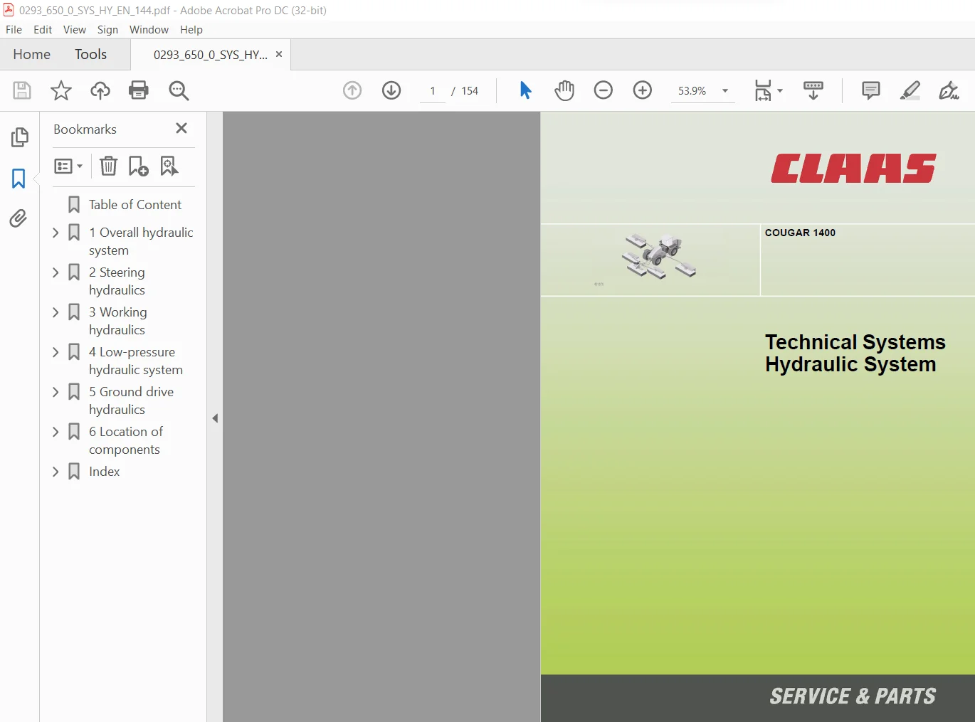
CLAAS COUGAR 1400 Technical & Hydraulic System Service Manual – PDF DOWNLOAD
Original price was: $80.00.$24.95Current price is: $24.95.
CLAAS COUGAR 1400 Technical & Hydraulic System Service Manual – PDF DOWNLOAD
Description
CLAAS COUGAR 1400 Technical & Hydraulic System Service Manual – PDF DOWNLOAD
DESCRIPTION:
CLAAS COUGAR 1400 Technical & Hydraulic System Service Manual – PDF DOWNLOAD
Description
When operating a consumer with a constant load (e.g. a hydraulic motor), the volume flow controller (772) is actuated to a stable position. This keeps both the pressure on the top face of the variable-displacement pump hydraulic cylinder (377) and the position of the swash plate (17) constant. As long as the position of the swash plate (17) remains unchanged, the pump pumps a constant volume flow.
TABLE OF CONTENTS:
CLAAS COUGAR 1400 Technical & Hydraulic System Service Manual – PDF DOWNLOAD
Table of Content 3
1 Overall hydraulic system 7
Hydraulic circuit diagram 7
Overall circuit diagram 8
Designations 9
PFC pump – compensation valve 20
Graphic 20
Designations 20
Description of function 21
PFC pump – initial position (Engine OFF) 22
Graphic 22
Designations 22
Description of 23
PFC pump – low-pressure standby 24
Graphic 24
Designations 24
Description of 25
PFC pump – pump changes to delivery mode 26
Graphic 26
Designations 26
Description of 27
PFC pump – constant volume flow 28
Graphic 28
Designations 28
Description of 29
PFC pump – downstroking 30
Graphic 30
Designations 30
Description of 31
PFC pump – maximum pressure limitation (pressure relief valve function) 32
Graphic 32
Designations 32
Description of 33
2 Steering hydraulics 35
System concept 35
Description 35
Emergency steering mode 37
Hydraulic circuit diagram 38
Designations 39
Function 43
The motor axle steered by the Orbitrol steering unit 45
Hydraulic circuit diagram 46
Designations 47
Function 51
Fully electronic steering mode (steer-by-wire) 53
Hydraulic circuit diagram 54
Designations 55
Function 59
Steering hydraulics valve block 61
Graphics 62
Designations 63
3 Working hydraulics 65
Hydraulic circuit diagram 65
Working hydraulics circuit diagram 66
Designations 67
Working hydraulics valve block 73
Graphics 74
Designations 75
Side arm solenoid valve 76
Graphics 77
Designations 78
Discription of function 79
Front power lift solenoid valve, front mower unit 79
Graphics 80
Designations 81
Discription of function 82
Constant-pressure system valve block 82
Graphics 83
Designations 84
Upper link, safety frame solenoid valve 84
Graphics 85
Designations 86
Discription of function 86
Cab rotation solenoid valve 86
Graphics 87
Designations 88
Discription of function 89
Constant-pressure system solenoid valve 89
Graphics 90
Designations 91
Description of function 91
Testing and measuring 92
Graphic 92
4 Low-pressure hydraulic system 93
Hydraulic circuit diagram 93
Low-pressure hydraulic system circuit diagram 94
Designations 95
Low-pressure hydraulic system valve block 96
Graphics 97
Designations 98
Discription of function 99
4-Trac solenoid valve, differential lock, gearbox shifting, drive clutch 99
Graphic 100
Designations101
Discription of function101
Testing and measuring102
Graphic 102
Designations102
5 Ground drive hydraulics105
Hydraulic circuit diagram105
Ground drive hydraulics circuit diagram106
Designations107
Ground drive control111
Ground drive variable-displacement pump (211)111
Additional feed and ground drive cooling113
Ground drive forward/reverse solenoid coil, shut-off valve114
Ground drive variable-displacement motor115
Testing and measuring117
Pressure testing using the signals from the high-pressure sensors B97, B98117
Measured value table117
6 Location of components119
Overview119
Main sub-assemblies (I to XI)119
Component grid (DIN A3)149
Figures149
Index151
IMAGES PREVIEW OF THE MANUAL:
Questions? Email us: [email protected]
https://vimeo.com/676558409
CLAAS COUGAR 1400 TECHNICAL & HYDRAULIC SYSTEM SERVICE MANUAL – PDF DOWNLOAD:
PLEASE NOTE:
- This is the same manual used by the dealers to diagnose and troubleshoot your vehicle
- You will be directed to the download page as soon as the purchase is completed. The whole payment and downloading process will take anywhere between 2-5 minutes
- Need any other service / repair / parts manual, please feel free to contact [email protected] . We still have 50,000 manuals unlisted
S.M