CLAAS CUTTERBAR VARIO 5.40 M- 7.50 M Repair manual – PDF DOWNLOAD
Original price was: $78.00.$24.95Current price is: $24.95.
CLAAS CUTTERBAR VARIO 5.40 M- 7.50 M Repair manual – PDF DOWNLOAD
Description
CLAAS CUTTERBAR VARIO 5.40 M- 7.50 M Repair manual – PDF DOWNLOAD
DESCRIPTION:
CLAAS CUTTERBAR VARIO 5.40 M- 7.50 M Repair manual – PDF DOWNLOAD
General information
- Introduction This CLAAS REPAIR MANUAL is to assist in preserving the permanent working order and therefore the high value of your CLAAS round baler by careful maintenance and service.
- Experience gathered by both our service engineers and factory staff has been compiled in this REPAIR MANUAL. The figures explain the procedure of repairs and the text describes the different adjustments to be made, the use of CLAAS special tools etc.
- The illustrations included in support to the explanations show the sequence of major repairs so that minor repairs can easily be followed. The CLAAS REPAIR MANUAL is filed in a folder which allows to insert supplementary pages as issued following technical developments and to always have an updated manual at hand for reference.
- To be sure, always compare settings and filling capacities with specifications stated in the current Operator’s Manual which applies to the machine.
TABLE OF CONTENTS:
CLAAS CUTTERBAR VARIO 5.40 M- 7.50 M Repair manual – PDF DOWNLOAD
1 General information
General 111
Introduction 111
Introduction to the CLAAS REPAIR MANUAL 112
Key to symbols 113
Safety rules 121
Important information 121
Identification of warning and danger signs 122
Correct use of the round baler 122
General safety and accident prevention regulations 122
Leaving the combine harvester 123
Service 123
Basic rule 123
Hydraulic accumulators 123
General repair information 131
Reason of damage 131
Spare parts 131
Transmission 131
Tensioning the steel roller chains 131
Taper ring fasteners 131
Self-locking bolts 131
Liquid locking compound 131
Correct installation of lock collar bearings 132
Correct installation of adapter sleeve bearings 132
Ferrule fittings on hydraulic lines 132
Progressive ring fittings on hydraulic lines 133
Taper fittings on hydraulic lines 133
Welding 133
Some advice for speedy and correct repair work: 134
Tightening torques 141
Bolts 141
Hydraulic screw fittings 142
Specifications 151
Lubricants chart 151
Drive diagram 161
General information on drives 161
Drive diagram, left-hand: 161
Drive diagram, right-hand: 162
2 Crop dividers
Crop dividers 211
Removing the crop dividers 211
Installing the crop dividers 211
3 Cutterbar trough – Cutter bar
Cutterbar trough – Cutter bar 311
Removing the VARIO table 311
Mounting the VARIO table 313
Adjusting the potentiometer sensing band 316
Replacing the support bracket 317
Adjusting the slide bars 317
Cleaning the slide bars (19) 317
Cutterbar lock 321
Removing the cutterbar lock 321
Mounting and adjusting the cutterbar lock 322
Cutter bar 331
Removing the knives 331
Installing the knife 331
Adjusting the knife height 332
4 Drives
Main drive universal drive shaft 411
Removing the main drive universal drive shaft 411
Disassembling the main drive universal drive shaft 411
Assembling the main drive universal drive shaft 415
Mounting the main drive universal drive shaft 416
Intermediate drive, left-hand 421
Removing the left-hand intermediate drive 421
Installing the left-hand intermediate drive shaft 422
Removing the hydraulic pump drive shaft 423
Installing the hydraulic pump drive shaft 426
Knife drive 431
Removing the knife drive belt (40) 431
Installing and adjusting the knife drive belt (40) 432
Adjusting the knife drive pull cylinder 433
Adjusting the limit switch 433
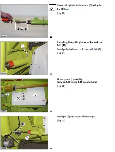
Removing the pull cylinder
of knife drive belt (40) 434
Disassembling the pull cylinder of knife drive belt (40) 436
Assembling the pull cylinder of knife drive belt (40) 436
Installing the pull cylinder of knife drive belt (40) 437
Removing the wobble transmission
(spare part no 643 6561 and spare part no 643 6562) 439
Disassembling the wobble transmission
(spare part no 643 6561
and spare part no 643 6562) 4310
Assembling the wobble transmission (spare part
no 643 6561 and spare part no 643 6562) 4315
Installing the wobble transmission (spare part
no 643 6561 and spare part no 643 6562) 4322
Removing the wobble transmission
(spare part no 637 5340) 4325
Disassembling the wobble transmission
(spare part no 637 5340) 4326
Assembling the wobble transmission
(spare part no 637 5340) 4430
Installing the wobble transmission
(spare part no 637 5340) 4435
Removing the deflection pulley of knife drive (40) 4437
Deflection pulley of knife drive (40), disassembled 4438
Installing the jockey pulley of knife drive (40) 4438
Removing the jockey pulleys of knife drive belt (40) 4438
Jockey pulley of knife drive (40), disassembled 4438
Jockey pulley of knife drive (40), disassembled 4439
Mounting the jockey pulleys of knife drive (40) 4439
5 Intake auger
Intake auger drive 511
Removing the feed drive chain (41) 511
Installing and adjusting the feed drive chain (41) 512
Removing the intake auger slip clutch 513
Intake auger slip clutch, disassembled 514
Mounting the intake auger slip clutch 515
Intake auger 521
Removing the left-hand intake auger bearing 521
Left-hand intake auger bearing, disassembled 523
012 RHB SW VARIO 5,40 m – 7,50 m – 299 2030
Contents
Installing the left-hand intake auger bearing 524
Removing the left-hand intake auger drive shaft 527
Installing the left-hand intake auger drive shaft 528
Removing the right-hand intake auger bearing 528
Right-hand intake auger bearing, disassembled 5211
Installing the right-hand intake auger bearing 5212
Removing the right-hand intake auger flange 5213
Installing the right-hand intake auger flange 5215
Removing the adjusting shaft 5217
Installing the adjusting shaft 5217
Removing the control shaft 5217
Installing the control shaft 5221
Removing the intake auger finger 5224
Installing the intake auger fingers 5225
Removing the intake auger 5226
Installing the intake auger 5227
6 Reel
Reel drive belt / drive chains 611
Removing the reel drive chain (42) 611
Installing and adjusting the reel drive chain (42) 612
Removing the reel drive chain (46) 613
Installing and adjusting the reel drive chain (46) 614
Removing the sprocket of reel drive chain (46) 614
Mounting the sprocket of reel drive chain (46) 615
Removing the reel drive belt (43) 616
Installing the reel drive belt (43) 617
Regelscheiben Haspelantrieb ausbauen 617
Regelscheiben Haspelantrieb einbauen 617
Reel drive universal drive shaft / angle drive 621
Removing the reel drive universal drive shaft with
friction clutch 621
Disassembling the reel drive universal drive shaft with
friction clutch 622
Assembling the reel drive universal drive shaft with
friction clutch 626
Mounting the reel drive universal drive shaft with
friction clutch 627
Replacing the friction linings of the reel drive
universal drive shaft with friction clutch 629
Mounting the friction linings of reel drive
universal drive shaft with friction clutch 629
Adjusting the slip clutch 629
Removing the rear angle drive 6210
Disassembling the rear angle drive 6211
Assembling the rear angle drive 6214
Mounting the rear angle drive 6215
Removing the front angle drive 6216
Disassembling the front angle drive 6216
Assembling the front angle drive 6221
Mounting the front angle drive 6224
Electric reel speed adjustment 631
Removing the electric reel variable-speed pulley 631
Electric reel variable-speed pulley, disassembled 633
Mounting the electric reel variable-speed pulley 634
Removing the electric reel speed adjustment
(up to machine no) 635
Disassembling the electric reel speed adjustment
(up to machine no) 636
Assembling the electric reel speed adjustment
(up to machine no) 639
Mounting the electric reel speed adjustment
(up to machine no) 6311
Removing the electric reel speed adjustment
(from machine no) 6312
Electric reel-speed adjustment, disassembled
(from machine no) 6313
Mounting the electric reel-speed adjustment
(from machine no) 6314
Removing the reel variable-speed drive bearing tube 6315
Reel variable-speed drive bearing tube,
disassembled 6316
Assembling and installing the reel variable-speed drive
bearing tube 6316
Removing the spring-loaded reel variable-speed pulley 6317
Spring-loaded reel variable-speed pulley,
disassembled 6319
Mounting the spring-loaded reel variable-speed pulley 6320
Reel 641
Removing the reel 641
Installing the reel 642
Reel height adjustment
(Basic setting) 644
Reel, disassembled 647
Removing the reel bearing 648
Installing the reel bearing 648
Removing the control rollers 649
Installing the control rollers 6410
Checking and adjusting the track of control rollers 6410
Removing the outside right-hand reel spider 6412
Mounting the outside right-hand reel spider 6412
Removing the outside left-hand control spider 6413
Mounting the outside left-hand control spider 6413
Removing the outside left-hand reel spider 6414
Mounting the outside left-hand reel spider 6414
Removing the reel shaft
(on 750 m cutterbars) 6415
Installing the reel shaft
(on 750 m cutterbars) 6416
Removing the centre reel spider 6417
Mounting the centre reel spider 6418
7 Hydraulic system / Electric system
Control valves 711
Removing the cutterbar control valve block 711
Cutterbar control valve block, disassembled 712
Assembling and installing the cutterbar control valve
block 713
Replacing the non-return valve 713
Removing the Reel lower 2/2-way valve (Y23) 714
Reel lower 2/2-way valve (Y23), disassembled 715
Installing the reel lower 2/2-way valve (Y23) 716
Removing the reel backward 3/2-way valve (Y25) 717
Reel backward 3/2-way valve (Y25), disassembled 717
Installing the reel backward 3/2-way valve (Y25) 718
Removing the lock-up valve unit
of reel backward valve (Y25) 719
299 2030 – RHB SW VARIO 5,40 m – 7,50 m 013
Contents
Disassembling the lock-up valve unit
of reel backward valve (Y25) 7110
Assembling the lock-up valve unit
of reel backward valve (Y25) 7110
Installing the lock-up valve unit
of reel backward valve (Y25) 7110
Hydraulic cylinders 721
Removing the left-hand double-acting reel height
adjustment hydraulic cylinder 721
Disassembling the left-hand double-acting reel height
adjustment hydraulic cylinder 722
Assembling the left-hand double-acting reel height
adjustment hydraulic cylinder 724
Installing the left-hand double-acting reel height adjustment
hydraulic cylinder 726
Removing the right-hand single-acting reel height
adjustment hydraulic cylinder 726
Disassembling the right-hand single-acting reel height
adjustment hydraulic cylinder 727
Assembling the right-hand single-acting
reel height adjustment hydraulic cylinder 7210
Installing the right-hand single-acting reel height
adjustment hydraulic cylinder 7212
Removing the reel horizontal adjustment
hydraulic cylinder 7212
Disassembling the reel horizontal adjustment
hydraulic cylinder 7213
Assembling the reel horizontal adjustment
hydraulic cylinder 7215
Installing the reel horizontal adjustment
hydraulic cylinder 7216
Removing the VARIO table hydraulic cylinder 7217
Disassembling the VARIO table hydraulic cylinder 7218
Assembling the VARIO table hydraulic cylinder 7221
Installing the VARIO table hydraulic cylinder 7223
Hydraulic motors / pumps 731
Removing the rape side cutter hydraulic pump 731
Mounting the rape side cutter hydraulic pump 732
8 Index
Index 811
IMAGES PREVIEW OF THE MANUAL:
CLAAS CUTTERBAR VARIO 5.40 M- 7.50 M REPAIR MANUAL – PDF DOWNLOAD:
PLEASE NOTE:
- This is the SAME MANUAL used by the dealerships to diagnose your vehicle
- No waiting for couriers / posts as this is a PDF manual and you can download it within 2 minutes time once you make the payment.
- Your payment is all safe and the delivery of the manual is INSTANT – You will be taken to the DOWNLOAD PAGE.
- So have no hesitations whatsoever and write to us about any queries you may have : heydownloadss @gmail.com
s.m