Trusted Business
Verified & Licensed
Virus Free Files
100% Safe Downloads
Secure Payment
SSL Protected
Instant Delivery
Available Immediately
Sale!


CLAAS Cutting Unit C490 – C370 Repair Manual – PDF DOWNLOAD
Original price was: $98.95.$29.95Current price is: $29.95.
CLAAS Cutting Unit C490 – C370 Repair Manual – PDF DOWNLOAD
Instant PDF Download
Available immediately
Save to Your Device
Download & keep forever
Antivirus Scanned
100% virus-free
Trusted Worldwide
175,000+ customers
Description
CLAAS Cutting Unit C490 – C370 Repair Manual – PDF DOWNLOAD
DESCRIPTION:
CLAAS Cutting Unit C490 – C370 Repair Manual – PDF DOWNLOAD
General Information :
Using the manual:
This repair manual should help you to maintain ongoing operational capacity. The high value of the harvesting machine is ensured through careful maintenance and technical monitoring by customer service. This repair manual is a compilation of our service technicians’ and shop-floor experience. The image sequence demonstrates the steps in a repair procedure.
- The text provides you with the information required for making adjustments, using special tools and further similar information. Essential repairs are listed in such a way that even individual and small repairs can be easily found and followed.
- Supplements are added to reflect the ongoing technical development of the machines and the manual is thereby continuously being updated as a reference book. As a precaution, always compare the setting values and fill quantities with the most recent operator’s manual for the respective machine.
TABLE OF CONTENTS:
CLAAS Cutting Unit C490 – C370 Repair Manual – PDF DOWNLOAD
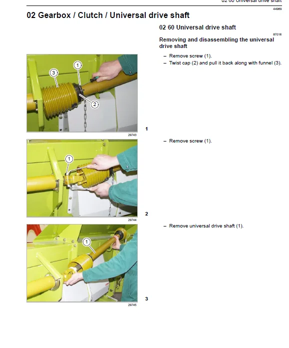
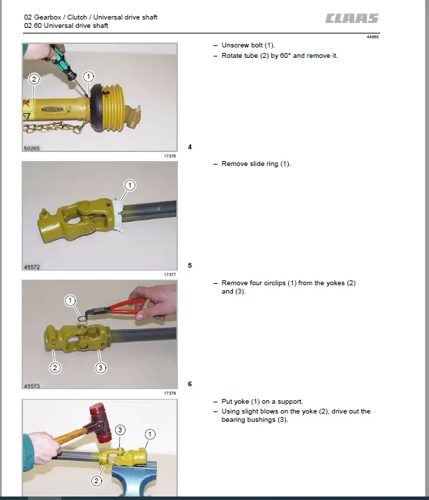
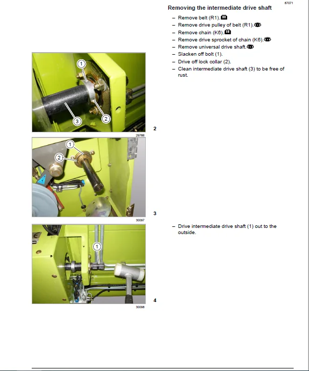
Contents........................................................................................................................  3
Introduction....................................................................................................................  7
	General Information.........................................................................................................  7
		Using the manual........................................................................................................  7
		Validity of instructions................................................................................................  9
	General repair instructions................................................................................................. 10
		Specifications.......................................................................................................... 10
		Reason of damage........................................................................................................ 10
		Spare parts............................................................................................................. 10
		Gearboxes............................................................................................................... 10
		Welding Work............................................................................................................ 10
		Tensioning the steel roller chains...................................................................................... 11
		Taper ring fasteners.................................................................................................... 11
		Gib head key joints..................................................................................................... 11
		Self-locking bolts with micro-encapsulated adhesive..................................................................... 12
		Liquid locking compound................................................................................................. 12
		Lock collar bearing..................................................................................................... 13
		Adapter sleeve bearing.................................................................................................. 13
		Ferrule fittings on hydraulic lines..................................................................................... 14
		Progressive ring fittings on hydraulic lines............................................................................ 14
		Taper fittings on hydraulic lines....................................................................................... 16
		Hydraulic hoses......................................................................................................... 16
		Some advice for speedy and correct repair work.......................................................................... 18
	Torque settings............................................................................................................. 19
		Tightening torques for metric standard threads.......................................................................... 19
		Tightening torques for metric fine threads.............................................................................. 20
		Tightening torques for hydraulic screw fittings with ferrule according to DIN 3861...................................... 21
		Tightening torques for hydraulic screw fittings and air conditioner fittings with a sealing cone and O-ring DIN 3865.... 22
		Tightening torques for hydraulic male connector DIN 3901................................................................ 23
		Tightening torques for direction-adjustable hydraulic male connectors ISO 6149-2 / ISO 11926-2 (3)...................... 24
		Tightening torque for hydraulic swivelling screw fittings............................................................... 25
		Tightening torques for hollow screws DIN 7643........................................................................... 26
		Tightening torques of brake line screw fittings......................................................................... 27
		Tightening torques for screw thread clamps.............................................................................. 28
	Specifications.............................................................................................................. 29
		Lubricants.............................................................................................................. 29
CCN explanations................................................................................................................ 30
	CCN (CLAAS Component Number)................................................................................................ 30
		General................................................................................................................. 30
		Electric system standard................................................................................................ 30
		Hydraulic system standard............................................................................................... 31
Safety precautions.............................................................................................................. 32
	General information......................................................................................................... 32
		Important notice........................................................................................................ 32
		Identification of warning and danger signs.............................................................................. 32
		General safety and accident prevention regulations...................................................................... 33
		Front attachments and trailers.......................................................................................... 33
		Adjustment and maintenance work......................................................................................... 34
		Danger of injury due to escaping hydraulic liquid....................................................................... 35
		First aid measures...................................................................................................... 35
		Jack up the machine..................................................................................................... 36
		Putting the machine out of action....................................................................................... 36
02 Gearbox / Clutch / Universal drive shaft..................................................................................... 37
	02 60 Universal drive shaft................................................................................................. 37
		Removing and disassembling the universal drive shaft.................................................................... 37
		Universal drive shaft overview.......................................................................................... 40
		Assembling and installing the universal drive shaft..................................................................... 41
08 Drives....................................................................................................................... 46
	08 00 Drive diagram......................................................................................................... 46
		Drive diagram........................................................................................................... 46
	08 14 Intermediate drive shaft.............................................................................................. 47
		Removing the intermediate drive shaft................................................................................... 47
		Intermediate drive shaft - Overview..................................................................................... 49
		Installing the intermediate drive shaft................................................................................. 49
09 Hydraulic system............................................................................................................. 51
	09 15 Hydraulic lines....................................................................................................... 51
		Overview of front attachment multi-coupler (8011)....................................................................... 51
	09 20 Valves................................................................................................................ 53
		Overview of reel adjustment valve block................................................................................. 53
	09 20 Special tools for valves.............................................................................................. 55
		Pulling out the valve insert............................................................................................ 55
		Screwing out the iron core.............................................................................................. 55
		Dismounting the seal.................................................................................................... 55
20 Crop feeding................................................................................................................. 56
	20 15 Reel.................................................................................................................. 56
		Removing the reel....................................................................................................... 56
		Installing the reel..................................................................................................... 57
		Removing the reel shaft bearing......................................................................................... 58
		Overview of reel shaft bearing.......................................................................................... 59
		Installing the reel shaft bearing....................................................................................... 60
		Overview of reel speed sensor (B017).................................................................................... 61
		Overview of vertical reel position sensor (B039)........................................................................ 62
		Removing the left reel support arm...................................................................................... 63
		Installing the left reel support arm.................................................................................... 65
		Removing the right reel support arm..................................................................................... 66
		Installing the right reel support arm................................................................................... 67
		Removing the right reel spider.......................................................................................... 69
		Overview of right reel spider........................................................................................... 70
		Installing the right reel spider........................................................................................ 70
		Removing the centre reel spider......................................................................................... 71
		Overview of centre reel spider.......................................................................................... 72
		Installing the centre reel spider....................................................................................... 72
		Removing the left reel spider........................................................................................... 73
		Overview of left reel spider............................................................................................ 74
		Installing the left reel spider......................................................................................... 74
		Removing the control spider............................................................................................. 75
		Overview of control spider.............................................................................................. 77
		Installing the control spider........................................................................................... 77
		Removing the reel tine tube............................................................................................. 79
		Installing the reel tine tube........................................................................................... 80
		Removing the reel drive................................................................................................. 81
		Overview of reel drive chain (K9)....................................................................................... 82
		Installing the reel drive............................................................................................... 83
		Overview of drive sprocket chain (K9)................................................................................... 84
		Overview of driven sprocket of chain (K9)............................................................................... 85
		Removing the hydraulic fore and aft reel adjustment hydraulic cylinder (3016)........................................... 86
		Overview of hydraulic fore and aft reel adjustment hydraulic cylinder (3016)............................................ 87
		Installing the hydraulic fore and aft reel adjustment hydraulic cylinder (3016)......................................... 88
		Removing the left reel height adjustment hydraulic cylinder (3015)...................................................... 89
		Overview of left reel height adjustment hydraulic cylinder (3015)....................................................... 90
		Installing the left reel height adjustment hydraulic cylinder (3015).................................................... 91
		Removing the right reel height adjustment hydraulic cylinder (3014)..................................................... 92
		Overview of right reel height adjustment hydraulic cylinder (3014)...................................................... 93
		Installing the right reel height adjustment hydraulic cylinder (3014)................................................... 94
		Removing the hydraulic reel drive motor (2012).......................................................................... 95
		Overview of reel drive hydraulic motor (2012)........................................................................... 96
		Installing the hydraulic reel drive motor (2012)........................................................................ 97
21 Feeder unit.................................................................................................................. 98
	21 40 Feed roller........................................................................................................... 98
		Removing the feed roller................................................................................................ 98
		Installing the feed roller.............................................................................................. 98
		Removing the left feed roller bearing................................................................................... 99
		Overview of left feed roller bearing....................................................................................101
		Installing the left feed roller bearing.................................................................................101
		Removing the right feed roller bearing..................................................................................105
		Installing the right feed roller bearing................................................................................106
		Removing the adjusting shaft............................................................................................108
		Overview of adjusting shaft.............................................................................................110
		Installing the adjusting shaft..........................................................................................110
		Removing the control shaft..............................................................................................113
		Overview of control shaft...............................................................................................115
		Installing the control shaft............................................................................................115
		Overview of feed roller drive chain (K6)................................................................................117
		Removing the driven sprocket of chain (K6) along with the slip clutch...................................................117
		Overview of driven sprocket of chain (K6) with slip clutch..............................................................119
		Installing the driven sprocket of chain (K6) along with the slip clutch.................................................120
	21 40 Feed roller special tools.............................................................................................122
		Removing / installing the feed roller bearing...........................................................................122
		Removing / installing the driven sprocket of chain (K6) along with the slip clutch......................................123
23 Mower unit...................................................................................................................125
	23 05 Mower head............................................................................................................125
		Removing and disassembling the wobble transmission......................................................................125
		Overview of wobble transmission.........................................................................................128
		Assembling and installing the wobble transmission.......................................................................129
		Overview of knife drive belt (R1).......................................................................................135
		Overview of jockey pulley belt (R1).....................................................................................136
		Overview of guide roller of belt (R1)...................................................................................137
		Removing the driven pulley of belt (R1).................................................................................138
		Overview of driven pulley of belt (R1)..................................................................................139
		Installing the driven pulley of belt (R1)...............................................................................140
	21 23 Mower unit special tools..............................................................................................141
		Disassembling / assembling the wobble transmission......................................................................141
		Installing the guide roller of belt (R1)................................................................................144
26 Ground guidance..............................................................................................................145
	26 05 AUTO CONTOUR..........................................................................................................145
		Overview of AUTO CONTOUR sensor band sensors (B003 / B004)..............................................................145
80 Various components / machine body............................................................................................147
	80 10 Lock..................................................................................................................147
		Removing the front attachment lock......................................................................................147
		Overview of front attachment lock.......................................................................................149
		Installing the front attachment lock....................................................................................149
CCN (CLAAS Component Number)....................................................................................................151
	2...........................................................................................................................151
	3...........................................................................................................................151
	4...........................................................................................................................151
	7...........................................................................................................................151
	8...........................................................................................................................151
	B...........................................................................................................................151
	Y...........................................................................................................................151
Index...........................................................................................................................152
	A...........................................................................................................................152
	B...........................................................................................................................152
	C...........................................................................................................................152
	D...........................................................................................................................152
	E...........................................................................................................................152
	F...........................................................................................................................152
	G...........................................................................................................................152
	H...........................................................................................................................153
	I...........................................................................................................................153
	J...........................................................................................................................153
	M...........................................................................................................................153
	R...........................................................................................................................153
	S...........................................................................................................................154
	T...........................................................................................................................154
	U...........................................................................................................................154
	V...........................................................................................................................154
	W...........................................................................................................................154
IMAGES PREVIEW OF THE MANUAL:
CLAAS CUTTING UNIT C490 – C370 REPAIR MANUAL – PDF DOWNLOAD:
PLEASE NOTE:
- This is the same manual used by the dealers to diagnose and troubleshoot your vehicle
- You will be directed to the download page as soon as the purchase is completed. The whole payment and downloading process will take anywhere between 2-5 minutes
- Need any other service / repair / parts manual, please feel free to contact [email protected] . We still have 50,000 manuals unlisted
S.V