CLAAS DOMINATOR 108/98/88 VX Service Repair Manual PDF Download
Original price was: $78.00.$29.95Current price is: $29.95.
CLAAS DOMINATOR 108 VX DOMINATOR 98 VX DOMINATOR 88 VX REPAIR MANUAL – PDF DOWNLOAD
Description
CLAAS DOMINATOR 108 VX DOMINATOR 98 VX DOMINATOR 88 VX REPAIR MANUAL – PDF DOWNLOAD
DESCRIPTION:
CLAAS DOMINATOR 108 VX DOMINATOR 98 VX DOMINATOR 88 VX REPAIR MANUAL – PDF DOWNLOAD
GENERAL INFORMATION
Introduction
- This CLAAS REPAIR MANUAL has been prepared to assist all personnel concerned with the maintenance and service of CLAAS combines and to help preserve their permanent working order and thus, their high value. Experience gathered by both our service engineers and factory staff has been compiled in this CLAAS REPAIR MANUAL which explains the
- procedure of repairs, the different adjustments to be made, the use of CLAAS special tools etc. The illustrations included in support to the explanations show the sequence of major repairs so that minor repairs can easily be drawn out. The CLAAS REPAIR MANUAL is filled in a folder which allows to insert supplementary pages as issued following technical
- developments and to have always an updated manual at hand for reference. To be sure, always compare settings and filling capacities with specifications stated in the current Operator’s Manual which applies to the machine.
Introduction to the CLAAS-REPAIR MANUAL
- The present CLAAS-REPAIR MANUAL is divided into main groups and subgroups. The first figure at the bottom of each page refers to the main group whereas the second figure following the point indicates the subgroup; the figure behind the oblique stroke gives the numerical order of the pages.
- Page numbering starts always with the number 1 in each subgroup. Where service operations apply to a specific machine model only, this is clearly indicated in headings. When a service procedure applies to all machines covered by this book, the machine names are not especially mentioned. When supplements are to be added, subgroups are supplemented or
- exchanged. All supplements are inserted in the respective main group / subgroup and the index is exchanged. The symbols communicate brief messages when recurring service procedures are described. Their meaning is explained at the beginning of this manual. The section «GENERAL REPAIR INSTRUCTIONS» at the beginning of this book contains useful practical
- hints. Read and follow these fundamental instructions. They are the basis for reliable service and durability of parts after repairs have been carried out. The description of a particular service procedure can easily be found by checking the list of contents of the appropriate main group / subgroup.
TABLE OF CONTENTS:
CLAAS DOMINATOR 108 VX DOMINATOR 98 VX DOMINATOR 88 VX REPAIR MANUAL – PDF DOWNLOAD
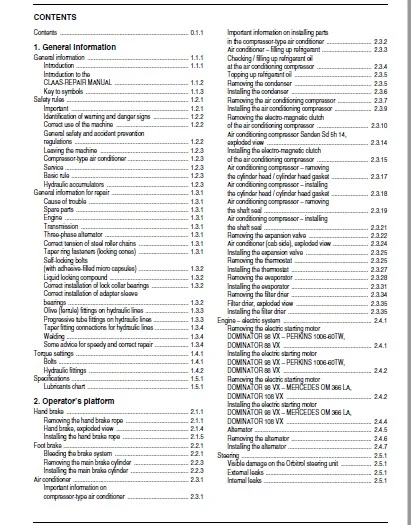
CONTENTS
Contents 011
1 General information
General information 111
Introduction 111
Introduction to the
CLAAS-REPAIR MANUAL 112
Key to symbols 113
Safety rules 121
Important 121
Identification of warning and danger signs 122
Correct use of the machine 122
General safety and accident prevention
regulations 122
Leaving the machine 123
Compressor-type air conditioner 123
Service 123
Basic rule 123
Hydraulic accumulators 123
General information for repair 131
Cause of trouble 131
Spare parts 131
Engine 131
Transmission 131
Three-phase alternator 131
Correct tension of steel roller chains 131
Taper ring fasteners (locking cones) 131
Self-locking bolts
(with adhesive-filled micro capsules) 132
Liquid locking compound 132
Correct installation of lock collar bearings 132
Correct installation of adapter sleeve
bearings 132
Olive (ferrule) fittings on hydraulic lines 133
Progressive tube fittings on hydraulic lines 133
Taper fitting connections for hydraulic lines 134
Welding 134
Some advice for speedy and correct repair 134
Torque settings 141
Bolts 141
Hydraulic fittings 142
Specifications 151
Lubricants chart 151
2 Operator’s platform
Hand brake 211
Removing the hand brake rope 211
Hand brake, exploded view 214
Installing the hand brake rope 215
Foot brake 221
Bleeding the brake system 221
Removing the main brake cylinder 223
Installing the main brake cylinder 223
Air conditioner 231
Important information on
compressor-type air conditioner 231
Important information on installing parts
in the compressor-type air conditioner 232
Air conditioner – filling up refrigerant 233
Checking / filling up refrigerant oil
at the air conditioning compressor 234
Topping up refrigerant oil 235
Removing the condenser 235
Installing the condenser 236
Removing the air conditioning compressor 237
Installing the air conditioning compressor 239
Removing the electro-magnetic clutch
of the air conditioning compressor 2310
Air conditioning compressor Sanden Sd 5h 14,
exploded view 2314
Installing the electro-magnetic clutch
of the air conditioning compressor 2315
Air conditioning compressor – removing
the cylinder head / cylinder head gasket 2317
Air conditioning compressor – installing
the cylinder head / cylinder head gasket 2318
Air conditioning compressor – removing
the shaft seal 2319
Air conditioning compressor – installing
the shaft seal 2321
Removing the expansion valve 2322
Air conditioner (cab side), exploded view 2324
Installing the expansion valve 2325
Removing the thermostat 2325
Installing the thermostat 2327
Removing the evaporator 2328
Installing the evaporator 2331
Removing the filter drier 2334
Filter drier, exploded view 2335
Installing the filter drier 2335
Engine – electric system 241
Removing the electric starting motor
DOMINATOR 98 VX – PERKINS 1006-60TW,
DOMINATOR 88 VX 241
Installing the electric starting motor
DOMINATOR 98 VX – PERKINS 1006-60TW,
DOMINATOR 88 VX 242
Removing the electric starting motor
DOMINATOR 98 VX – MERCEDES OM 366 LA,
DOMINATOR 108 VX 242
Installing the electric starting motor
DOMINATOR 98 VX – MERCEDES OM 366 LA,
DOMINATOR 108 VX 244
Alternator 245
Removing the alternator 246
Installing the alternator 247
Steering 251
Visible damage on the Orbitrol steering unit 251
External leaks 251
Internal leaks 251
Contents
E,”“三
012 RHB DOMINATOER 108 VX – 88 VX – 297 9770
Contents
Removing the steering column 252
Dismantling the steering column 256
Steering, exploded view 257
Assembling the steering column 258
Installing the steering column 259
Bleeding the steering hydraulic system 2512
Checking the pressure control valve at
the steering valve block 2513
Removing the steering unit valve block 2515
Dismantling the steering unit valve block 2515
Assembling the steering unit valve block 2518
Installing the steering unit valve block 2520
Removing the steering unit 2520
Installing the steering unit 2522
3 Threshing mechanism
Feeder housing 311
Removing the feeder housing 311
Installing the feeder housing 314
Removing the upper feed rake shaft 315
Upper feed rake shaft, exploded view
DOMINATOR 108 VX 3110
Upper feed rake shaft, exploded view
DOMINATOR 98 VX / 88 VX 3111
Installing the upper feed rake shaft 3112
Removing the lower feed rake roller 3114
Dismantling the lower feed rake roller 3117
Lower feed rake roller, exploded view 3119
Assembling the lower feed rake roller 3119
Installing the lower feed rake roller 3120
Replacing the feeder chains 3122
Removing the wooden ledges 3124
Installing the wooden ledges 3126
Removing the intermediate floor 3127
Installing the intermediate floor 3131
Replacing the slide rails 3132
Removing the intermediate drive shaft 3133
Installing the intermediate drive shaft 3136
Concave 321
Removing the stone trap 321
Installing the stone trap 322
Removing the concave 323
Installing the concave 327
Basic setting of concave 329
Threshing drum 331
Removing the left-hand threshing
drum bearing 331
Dismantling the left-hand threshing
drum bearing 335
Left-hand threshing drum bearing,
exploded view 336
Assembling the left-hand threshing
drum bearing 336
Installing the left-hand threshing
drum bearing 337
Removing the right-hand threshing
drum bearing 3311
Dismantling the right-hand threshing
drum bearing 3315
Right-hand threshing drum bearing,
exploded view 3315
Assembling the right-hand threshing
drum bearing 3316
Installing the right-hand threshing
drum bearing 3317
Removing the threshing drum 3319
Replacing the threshing drum rasp bars 3324
Replacing the threshing drum shaft 3326
Threshing drum, exploded view 3327
Installing the threshing drum 3328
Impeller 341
Removing the left-hand impeller bearing 341
Installing the left-hand impeller bearing 342
Removing the right-hand impeller bearing 343
Installing the right-hand impeller bearing 344
Removing the impeller 345
Dismantling the impeller 345
Impeller, exploded view 347
Assembling the impeller 348
Installing the impeller 349
4 Cleaning
Under-walker return floor 411
Removing the under-walker return floor
DOMINATOR 88 VX 411
Front rocker arm, exploded view 412
Rear rocker arm, exploded view 412
Installing the under-walker return floor 413
Straw walker 421
Removing the straw walker racks 421
Installing the straw walker racks 423
Removing the front straw walker shaft 425
Installing the front straw walker shaft 427
Removing the rear straw walker shaft 428
Installing the rear straw walker shaft 4211
Dismantling the straw walker shafts
(for straw walker shafts with ball bearings) 4214
Straw walker bearing, exploded view 4215
Assembling the straw walker shafts
(for straw walker shafts with ball bearings) 4215
Intensive separation system 431
Removing the front intensive
separation system shaft 431
Installing the front intensive
separation system shaft 434
Removing the rear intensive
separation system shaft 436
Installing the rear intensive
separation system shaft 438
Dismantling the intensive
separation system shaft 4310
Assembling the intensive
separation system shaft 4311
云’If1f,’
297 9770 – RHB DOMINATOER 108 VX – 88 VX 013
Contents
Removing the intensive separation
system control shaft 4311
Installing the intensive separation
system control shaft 4312
Replacing the agitator tines 4312
Sieve pan 441
Removing the upper sieves
With 3-D cleaning system 441
Installing the upper sieves
With 3-D cleaning system 441
Removing the upper sieves
Without 3-D cleaning system 441
Installing the upper sieves
Without 3-D cleaning system 441
Removing the lower sieves
With 3-D cleaning system 442
Installing the lower sieves
With 3-D cleaning system 442
Removing the lower sieves
Without 3-D cleaning system 443
Installing the lower sieves
Without 3-D cleaning system 443
Removing the 3-D cleaning system frame 444
Cleaning system frame, exploded view 447
Installing the 3-D cleaning system frame 448
Removing the sieve pan 4413
Installing the sieve pan 4417
Preparation floor 451
Removing the preparation floor 451
Preparation floor, exploded view 455
Installing the preparation floor 456
3-D cleaning system 461
Removing the 3-D cleaning system 461
Installing the 3-D cleaning system 461
3-D sieve pan suspension and cleaning system,
exploded view 462
Adjusting the 3-D cleaning system 464
Adjusting the pivot arm
using the «3-D gauge» 465
Rocker arm drive 471
Removing the rocker arm drive 471
Rocker arm drive, exploded view 475
Installing the rocker arm drive 477
Cleaning fan 481
Removing the bearings to the right-hand and
left-hand side of cleaning fan 481
Self-aligning ball bearing, exploded view 484
Installing the bearings to the right-hand and
left-hand side of cleaning fan 484
Removing the fan blast reduction
DOMINATOR 108 VX 486
Fan blast reduction, exploded view
DOMINATOR 108 VX 488
Installing the fan blast reduction
DOMINATOR 108 VX 489
Removing the fan shaft
DOMINATOR 108 VX 4811
Installing the fan shaft
DOMINATOR 108 VX 4813
Removing the centre cleaning fan bearing
DOMINATOR 108 VX 4815
Centre cleaning fan bearing,
exploded view 4816
Installing the centre cleaning fan bearing
DOMINATOR 108 VX 4816
Removing the fan rotors
DOMINATOR 108 VX 4816
Installing the fan rotors
DOMINATOR 108 VX 4817
Removing the fan housing
DOMINATOR 108 VX 4817
Installing the fan housing
DOMINATOR 108 VX 4818
Removing the wind boards
DOMINATOR 108 VX 4819
Installing the wind boards
DOMINATOR 108 VX 4819
Removing the fan shaft
DOMINATOR 98 – 88 VX 4820
Installing the fan shaft
DOMINATOR 98 – 88 VX 4820
Removing the fan spiders
DOMINATOR 98 – 88 VX 4821
Installing the fan spiders
DOMINATOR 98 – 88 VX 4821
Removing the fan rotor
DOMINATOR 98 – 88 VX 4822
Installing the fan rotor
DOMINATOR 98 – 88 VX 4823
Fan blades
DOMINATOR 98 – 88 VX 4823
Removing the fan housing
DOMINATOR 98 – 88 VX 4824
Installing the fan housing
DOMINATOR 98 – 88 VX 4825
Removing the wind boards
DOMINATOR 98 – 88 VX 4826
Installing the wind boards
DOMINATOR 98 – 88 VX 4826
5 Grain delivery
Returns elevator 511
Removing the returns elevator chain 511
Installing the returns elevator chain 513
Removing the upper returns auger 513
Installing the upper returns auger 516
Removing the returns elevator 517
Dismantling the returns elevator 5110
Assembling the returns elevator 5112
Installing the returns elevator 5113
Removing the lower returns auger 5115
Installing the lower returns auger 5119
Grain elevator 521
Removing the grain elevator chain
DOMINATOR 98 VX – 88 VX 521
E,”“三
014 RHB DOMINATOER 108 VX – 88 VX – 297 9770
Contents
Installing the grain elevator chain
DOMINATOR 98 VX – 88 VX 523
Removing the grain elevator chain
DOMINATOR 108 VX 523
Installing the grain elevator chain
DOMINATOR 108 VX 525
Removing the grain elevator top
DOMINATOR 98 VX – 88 VX 526
Removing the grain elevator top
DOMINATOR 108 VX 527
Dismantling the grain elevator top 527
Grain elevator top, exploded view 5211
Assembling the grain elevator top 5212
Installing the grain elevator top
DOMINATOR 98 VX – 88 VX 5215
Installing the grain elevator top
DOMINATOR 108 VX 5215
Removing the grain elevator shaft
DOMINATOR 108 VX 5216
Installing the grain elevator shaft
DOMINATOR 108 VX 5219
Removing the grain elevator boot
DOMINATOR 98 VX – 88 VX 5220
Installing the grain elevator boot
DOMINATOR 98 VX – 88 VX 5223
Removing the grain elevator boot
DOMINATOR 108 VX 5223
Installing the grain elevator boot
DOMINATOR 108 VX 5225
Removing the grain auger 5226
Installing the grain auger 5229
Removing the grain tank filler auger
DOMINATOR 98 VX – 88 VX 5231
Removing the grain tank filler auger
DOMINATOR 108 VX 5232
Dismantling the angle drive for grain tank
filler auger DOMINATOR 108 VX – 88 VX 5234
Grain tank filler auger, exploded view 5236
Assembling the angle drive for grain tank
filler auger DOMINATOR 108 VX – 88 VX 5237
Installing the grain tank filler auger
DOMINATOR 98 VX – 88 VX 5239
Installing the grain tank filler auger
DOMINATOR 108 VX 5240
Grain tank unloading 531
Removing the grain tank unloading auger 531
Installing the grain tank unloading auger 534
Removing the grain tank unloading tube auger 535
Installing the grain tank unloading tube auger 537
Removing the grain tank unloading tube 537
Installing the grain tank unloading tube 539
Removing the lateral augers
DOMINATOR 108 VX 5310
Installing the lateral augers
DOMINATOR 108 VX 5312
Chaff spreader 541
Removing the chaff spreader
flange housing 541
Dismantling the chaff spreader
flange housing 542
Assembling the chaff spreader
flange housing 543
Installing the chaff spreader
flange housing 545
Removing the chaff spreader drive shaft 546
Dismantling the chaff spreader drive shaft 547
Chaff spreader, exploded view 548
Assembling the chaff spreader drive shaft 5410
Installing the chaff spreader drive shaft 5410
6 Grain delivery
Straw spreader 611
Removing the straw spreader 611
Dismantling the straw spreader 612
Straw spreader, exploded view 615
Assembling the straw spreader 617
Installing the straw spreader 619
Straw chopper 621
Removing the right-hand
straw chopper bearing 621
Removing the left-hand
straw chopper bearing 623
Dismantling the left-hand / right-hand
straw chopper bearing 625
Assembling the left-hand / right-hand
straw chopper bearing 625
Installing the right-hand
straw chopper bearing 626
Installing the left-hand
straw chopper bearing 628
Removing the cutting cylinder 6210
Cutting cylinder, exploded view 6212
Pre-assembling the cutting cylinder 6213
Installing the cutting cylinder 6214
7 Drives
Drive belts 711
General instructions 711
Drive diagram, left-hand side 712
Drive diagram, right-hand side 713
Drive belts on left-hand side 721
Removing the cutterbar drive belt (1) 721
Installing and adjusting the
cutterbar drive belt (1) 723
Removing the compressor drive belt (2) 724
Installing and adjusting the
compressor drive belt (2) 724
Removing the hydrostatic
ground drive belt (3) 725
Installing and adjusting the
hydrostatic ground drive belt (3) 727
Removing the drive belt (4) for the
working hydraulics pump 729
云’If1f,’
297 9770 – RHB DOMINATOER 108 VX – 88 VX 015
Contents
Installing and adjusting the drive belt (4) for the
working hydraulics pump 729
Removing the threshing mechanism drive belt (5) 7210
Installing and adjusting the threshing mechanism
drive belt (5) 7212
Removing the grain tank discharge drive belt (6) 7213
Installing and adjusting the grain tank discharge
drive belt (6) 7215
Removing the sieve pan / fan intermediate
drive belt (7) 7216
Installing and adjusting the sieve pan / fan
intermediate drive belt (7) 7216
Removing the fan drive belt (8) 7217
Installing the fan drive belt (8) 7218
Removing the sieve pan
intermediate drive belt (9) 7219
Installing and adjusting the sieve pan
intermediate drive belt (9) 7219
Removing the sieve pan drive belt (10) 7220
Installing and adjusting the sieve pan
drive belt (10) 7221
Removing the straw walker drive belt (11) 7221
Installing and adjusting the straw walker
drive belt (11) 7222
Removing the intensive separation system
drive belt (12) 7223
Installing and adjusting intensive separation
drive belt (12) 7224
Removing the lateral auger drive belt (13)
DOMINATOR 88 VX 7225
Removing the straw spreader drive belt (14) 7225
Installing and adjusting the straw spreader
drive belt (14) 7226
Removing the chaff spreader drive belt (15) 7226
Installing and adjusting the chaff spreader
drive belt (15) 7227
Removing the chaff spreader drive belt (16) 7227
Installing and adjusting the chaff spreader
drive belt (16) 7227
Drive belts on right-hand side 731
Removing the straw chopper drive belt (20) 731
Installing and adjusting the straw chopper
drive belt (20) 732
Removing the straw chopper intermediate
drive belt (21) 733
Installing and adjusting the straw chopper
intermediate drive belt (21) 733
Removing the suction blower drive belt (22) 734
Installing and adjusting suction
blower drive belt (22) 735
Removing the threshing drum
speed control belt (23) 736
Installing and adjusting the threshing drum
speed control belt (23) 738
Removing the threshing drum
drive belt (24) 7310
Installing and adjusting the threshing drum
drive belt (24) 7312
Removing the threshing drum
speed control belt (25)
(excluding intermediate drive) 7313
Installing and tensioning the threshing drum
speed control belt (25)
(excluding intermediate drive) 7314
Removing the radiator chaff screen
drive belt (26) 7315
Installing the radiator chaff screen
drive belt (26) 7315
Removing the radiator chaff screen
intermediate drive belt (27) 7316
Installing and adjusting the radiator chaff screen
intermediate drive belt (27) 7316
Removing the grain elevator top drive chain (30)
DOMINATOR 108 VX 7317
Installing the grain elevator top drive chain (30)
DOMINATOR 108 VX 7317
Removing the grain elevator top drive chain (30)
DOMINATOR 98 VX / 88 VX 7318
Installing the grain elevator top drive chain (30)
DOMINATOR 98 VX / 88 VX 7319
Removing the grain tank unloading
intermediate drive chain (31) 7319
Installing and adjusting the grain tank unloading
intermediate drive chain (31) 7319
Removing the grain tank unloading
intermediate drive chain (32)
DOMINATOR 108 VX 7320
Installing and adjusting the grain tank unloading
intermediate drive chain (32)
DOMINATOR 108 VX 7320
Removing the returns drive chain (33) 7321
Installing and adjusting the returns
drive chain (33) 7321
Cutterbar drive 741
Removing the cutterbar clutch 741
Cutterbar clutch, exploded view 746
Installing the cutterbar clutch 749
Removing the front cutterbar drive pulley
(DOMINATOR 108 VX) 7415
Installing the front cutterbar drive pulley
(DOMINATOR 108 VX) 7415
Removing the front cutterbar drive pulley
(DOMINATOR 98 VX / 88 VX) 7415
Installing the front cutterbar drive pulley
(DOMINATOR 98 VX / 88 VX) 7416
Removing the cutterbar drive deflection pulley 7416
Cutterbar drive deflection pulley, exploded view 7416
Installing the cutterbar drive deflection pulley 7417
Removing the cutterbar drive slip clutch 7417
Dismantling the cutterbar drive slip clutch 7417
Cutterbar drive slip clutch, exploded view 7419
Assembling the cutterbar drive slip clutch 7419
Installing the cutterbar drive slip clutch 7421
Removing the cutterbar drive jockey pulley 7422
Cutterbar drive jockey pulley, exploded view 7422
Installing the cutterbar drive jockey pulley 7422
E,”“三
016 RHB DOMINATOER 108 VX – 88 VX – 297 9770
Contents
Left-hand threshing mechanism drive 751
Removing the threshing mechanism drive pulley 751
Installing the threshing mechanism drive pulley 751
Removing the threshing mechanism drive
jockey pulley 751
Threshing mechanism drive jockey pulley,
exploded view 752
Installing the threshing mechanism drive
jockey pulley 753
Right-hand threshing mechanism drive 761
Removing the threshing drum
variable-speed drive (spring-loaded) 761
Dismantling the threshing drum
variable-speed drive (spring-loaded) 763
Threshing drum variable-speed drive
(spring-loaded), exploded view 766
Assembling the threshing drum
variable-speed drive (spring-loaded) 767
Installing the threshing drum
variable-speed drive (spring-loaded) 7611
Removing the threshing drum
variable-speed drive (hydraulic) 7614
Dismantling the threshing drum
variable-speed drive (hydraulic) 7616
Threshing drum variable-speed drive
(hydraulic), exploded view 7618
Assembling the threshing drum
variable-speed drive (hydraulic) 7620
Installing the threshing drum
variable-speed drive (hydraulic) 7622
Removing the threshing drum drive jockey pulley
without threshing drum speed reduction kit
(DOMINATOR 108 VX),
with threshing drum speed reduction kit
(DOMINATOR 108 VX – 88 VX) 7624
Threshing drum drive jockey pulley,
exploded view 7624
Installing the threshing drum drive jockey pulley
without threshing drum speed reduction kit
(DOMINATOR 108 VX),
with threshing drum speed reduction kit
(DOMINATOR 108 VX – 88 VX) 7624
Threshing drum speed reduction kit 771
Removing the threshing drum speed reduction kit 771
Dismantling the threshing drum speed reduction kit 772
Threshing drum speed reduction kit, exploded view 777
Assembling the threshing drum speed reduction kit 778
Installing the threshing drum speed reduction kit 7714
Sieve pan intermediate drive 781
Removing the sieve pan / fan intermediate
drive jockey pulley 781
Sieve pan / fan intermediate drive jockey pulley,
exploded view 781
Installing the sieve pan / fan intermediate
drive jockey pulley 781
Straw walker drive 791
Removing the straw walker drive jockey pulley 791
Installing the straw walker drive jockey pulley 791
Removing the intensive separation system
drive deflection pulley 791
Installing the intensive separation system
drive deflection pulley 792
Removing the intensive separation system
drive jockey pulley 792
Installing the intensive separation system
drive jockey pulley 792
Straw walker drive, exploded view 793
Sieve pan drive 7101
Removing the straw walker / sieve pan
intermediate drive jockey pulley 7101
Dismantling the straw walker / sieve pan
intermediate drive jockey pulley 7101
Assembling the straw walker / sieve pan
intermediate drive jockey pulley 7102
Installing the straw walker / sieve pan
intermediate drive jockey pulley 7102
Removing the straw walker / sieve pan
intermediate drive V-belt pulley package 7103
Dismantling the straw walker / sieve pan
intermediate drive V-belt pulley package 7103
Assembling the straw walker / sieve pan
intermediate drive V-belt pulley package 7104
Installing the straw walker / sieve pan
intermediate drive V-belt pulley package 7105
Removing the sieve pan drive deflection pulley 7105
Straw walker / sieve pan intermediate drive,
exploded view 7106
Installing the sieve pan drive deflection pulley 7107
Removing the sieve pan drive jockey pulley 7107
Sieve pan drive jockey pulley, exploded view 7108
Installing the sieve pan drive jockey pulley 7108
Fan drive 7111
Removing the fan adjustment (electrical)
(Version A) 7111
Dismantling the fan adjustment (electrical)
(Version A) 7112
Fan adjustment (electrical), exploded view
(Version A) 7113
Assembling the fan adjustment (electrical)
(Version A) 7114
Installing the fan adjustment (electrical)
(Version A) 7117
Removing the fan adjustment (electrical)
(Version B) 7118
Dismantling the fan adjustment (electrical)
(Version B) 7119
Fan adjustment (electrical), exploded view
(Version B) 71111
Assembling the fan adjustment (electrical)
(Version B) 71112
Installing the fan adjustment (electrical)
(Version B) 71114
云’If1f,’
297 9770 – RHB DOMINATOER 108 VX – 88 VX 017
Contents
Removing the variable-speed fan drive
(electrical) 71115
Dismantling the variable-speed fan drive
(electrical) 71116
Variable speed fan drive (electrical),
exploded view 71118
Assembling the variable-speed fan drive
(electrical) 71119
Installing the variable-speed fan drive
(electrical) 71121
Aligning the variable speed fan pulleys 71125
Removing the variable-speed fan drive
(spring-loaded) 71126
Dismantling the variable-speed fan drive
(spring-loaded) 71127
Variable-speed fan drive (spring-loaded),
exploded view 71129
Assembling the variable-speed fan drive
(spring-loaded) 71130
Installing the variable-speed fan drive
(spring-loaded) 71132
Chaff spreader drive 7121
Removing the chaff spreader drive bracket 7121
Dismantling the chaff spreader drive bracket 7122
Assembling the chaff spreader drive bracket 7123
Installing the chaff spreader drive bracket 7123
Removing the chaff spreader drive jockey pulley 7124
Dismantling the chaff spreader drive jockey pulley 7124
Chaff spreader drive, exploded view 7126
Assembling the chaff spreader drive jockey pulley 7127
Installing the chaff spreader drive jockey pulley 7127
Grain tank unloading drive 7131
Removing the upper angle drive of
grain tank unloading 7131
Dismantling the upper angle drive of
grain tank unloading 7132
Upper angle drive of grain tank unloading,
assembled 7133
Assembling the upper angle drive of
grain tank unloading 7134
Installing the upper angle drive of
grain tank unloading 7136
Removing the lower angle drive of
grain tank unloading 7137
Dismantling the lower angle drive of
grain tank unloading 7138
Lower angle drive of grain tank unloading,
assembled 71312
Assembling the lower angle drive of
grain tank unloading 71313
Installing the lower angle drive of
grain tank unloading 71315
Removing the grain tank intermediate drive shaft 71316
Installing the grain tank intermediate drive shaft 71318
Removing the grain tank unloading drive
jockey pulley
(DOMINATOR 108 VX) 71320
Grain tank unloading drive jockey pulley,
exploded view
(DOMINATOR 108 VX) 71320
Installing the grain tank unloading drive
jockey pulley
(DOMINATOR 108 VX) 71320
Removing the grain tank unloading drive
jockey pulley
(DOMINATOR 98 VX / 88 VX) 71321
Grain tank unloading drive jockey pulley,
exploded view
(DOMINATOR 98 VX / 88 VX) 71321
Installing the grain tank unloading drive
jockey pulley
(DOMINATOR 98 VX / 88 VX) 71321
Removing the grain tank unloading auger
safety clutch 71322
Dismantling the grain tank unloading auger
safety clutch 71323
Grain tank unloading auger safety clutch,
exploded view 71323
Assembling the grain tank unloading auger
safety clutch 71324
Installing the grain tank unloading auger
safety clutch 71324
Removing the lateral auger drive
(DOMINATOR 108 VX) 71325
Installing the lateral auger drive
(DOMINATOR 108 VX) 71325
Straw chopper drive 7141
Removing the straw chopper intermediate drive
jockey pulley 7141
Straw chopper intermediate drive jockey pulley,
exploded view 7141
Installing the straw chopper intermediate drive
jockey pulley 7141
Removing the straw chopper intermediate drive 7142
Dismantling the straw chopper intermediate drive 7143
Assembling the straw chopper intermediate drive 7145
Installing the straw chopper intermediate drive 7147
Removing the straw chopper drive jockey pulley 7147
Straw chopper intermediate drive, exploded view 7148
Installing the straw chopper drive jockey pulley 7149
Straw spreader drive 7151
Removing the straw spreader tensioning device 7151
Dismantling the straw spreader tensioning device 7151
Straw spreader tensioning device, exploded view 7152
Assembling the straw spreader tensioning device 7153
Installing the straw spreader tensioning device 7153
Rotary radiator screen drive 7161
Removing the rotary radiator screen drive shaft 7161
Dismantling the rotary radiator screen drive shaft 7162
Rotary radiator screen drive, exploded view 7166
Assembling the rotary radiator screen drive shaft 7167
Installing the rotary radiator screen drive shaft 7169
E,”“三
018 RHB DOMINATOER 108 VX – 88 VX – 297 9770
Contents
Rotary radiator screen suction blower 7171
Removing the rotary radiator screen
suction blower 7171
Dismantling the rotary radiator screen
suction blower 7171
Rotary radiator screen suction blower,
exploded view 7174
Assembling the rotary radiator screen
suction blower 7175
Installing the rotary radiator screen
suction blower 7177
Hydraulic pump drive 7181
Removing the hydrostatic ground drive
jockey pulley
(DOMINATOR 108 VX) 7181
Hydrostatic ground drive jockey pulley,
exploded view
(DOMINATOR 108 VX) 7181
Installing the hydrostatic ground drive
jockey pulley
(DOMINATOR 108 VX) 7182
Removing the hydrostatic ground drive
jockey pulley
(DOMINATOR 98 VX / 88 VX) 7183
Hydrostatic ground drive jockey pulley,
exploded view
(DOMINATOR 98 VX / 88 VX) 7184
Installing the hydrostatic ground drive
jockey pulley
(DOMINATOR 98 / 88 VX) 7185
Final drives 7191
Removing the final drives 7191
Dismantling the final drives
DOMINATOR 108 VX 7192
Final drive, exploded view
DOMINATOR 108 VX 71911
Assembling the final drives
DOMINATOR 108 VX 71913
Dismantling the final drives
DOMINATOR 98 VX / 88 VX 71922
Assembling the final drives
DOMINATOR 98 VX / 88 VX 71929
Installing the final drives 71937
Transmission gearbox 7201
Lowering the transmission gearbox
with drum brakes
(DOMINATOR 108 VX / 88 VX) 7201
Raising the transmission gearbox
with drum brakes
(DOMINATOR 108 VX / 88 VX) 7207
Lowering the transmission gearbox
with disc brakes
(DOMINATOR 98 VX) 72012
Raising the transmission gearbox
with disc brakes
(DOMINATOR 98 VX) 72016
Removing the transmission gearbox 72020
Dismantling the gearbox
(DOMINATOR 108 VX) 72026
Assembling the gearbox
DOMINATOR 108 VX 72037
Dismantling the gearbox
(DOMINATOR 98 / 88 VX) 72044
Assembling the gearbox
(DOMINATOR 98 VX / 88 VX) 72057
Dismantling the differential
(DOMINATOR 108 VX – 88 VX) 72067
Differential, exploded view 72069
Assembling the differential
(DOMINATOR 108 VX – 88 VX) 72070
Installing the gearbox 72073
Parking brake 7211
Removing the brake units for the parking brake
with drum brakes
(DOMINATOR 108 VX / 88 VX) 7211
Installing the brake units for the parking brake
with drum brakes
(DOMINATOR 108 VX / 88 VX) 7213
Removing the brake units for the parking brake
with disc brakes
(DOMINATOR 98 VX) 7215
Installing the brake units for the parking brake
with disc brakes
(DOMINATOR 98 VX) 7216
Foot brake 7221
Bleeding the brake units 7221
Removing the brake shoes from the foot brake
with drum brakes
(DOMINATOR 108 VX / 88 VX) 7222
Installing the brake shoes from the foot brake
with drum brakes
(DOMINATOR 108 VX / 88 VX) 7224
Removing the wheel brake ram
with drum brakes
(DOMINATOR 108 VX / 88 VX) 7225
Installing the wheel brake ram
with drum brakes
(DOMINATOR 108 VX / 88 VX) 7226
Removing the brake cradle
with disc brakes (DOMINATOR 98 VX) 7226
Installing the brake cradle
with disc brakes (DOMINATOR 98 VX) 7228
Removing the brake pads
with disc brakes (DOMINATOR 98 VX) 7229
Installing the brake pads
with disc brakes (DOMINATOR 98 VX) 72210
Drive axle 7231
Removing the drive axle 7231
Installing the drive axle 7235
Steering axle 7241
Removing the wheel bearings
(205 m steering axle) 7241
Installing the wheel bearings
(205 m steering axle) 7243
云’If1f,’
297 9770 – RHB DOMINATOER 108 VX – 88 VX 019
Contents
Removing the stub axle
(205 m steering axle) 7246
Installing the stub axle
(205 m steering axle) 7248
Removing the wheel bearings
(adjustable axle) 72410
Installing the wheel bearings
(adjustable steering axle) 72412
Removing the stub axle
(adjustable steering axle) 72414
Installing the stub axle
(adjustable steering axle) 72416
Adjusting the steering axle end stops
(205 m steering axle,
adjustable steering axle) 72418
Adjusting the steering axle end stops
(CLAAS 4-trac axle) 72419
Wheel track adjustment 72420
Removing the steering axle 72422
Installing the steering axle 72425
Removing the CLAAS 4-trac axle 72427
Installing the CLAAS 4-trac axle 72430
Bleeding the hydraulic motors
(CLAAS 4-trac axle) 72433
Removing the planetary gearbox / hydraulic motor
(CLAAS 4-trac axle) 72435
Removing the stub axle housing
(CLAAS 4-trac axle) 72437
CLAAS 4-trac system, exploded view 72439
Installing the stub axle housing
(CLAAS 4-trac axle) 72440
Installing planetary gearbox / hydraulic motor
(CLAAS 4-trac axle) 72441
8
9 Hydraulics
Maintenance 911
Hydraulic system 911
Checking the hydraulic oil level 912
Changing the hydraulic oil 912
Hydraulic pump 921
Removing the double pump with the hydraulic tank 921
Dismantling the double pump and the hydraulic tank 923
Double pump and hydraulic tank, exploded view 925
Assembling the double pump and hydraulic tank 926
Installing the double pump and hydraulic tank 928
Check the double pump 929
Hydraulic ram – steering hydraulics 931
Removing the steering ram
(with 205 m steering axle) 931
Dismantling the steering ram
(with 205 m steering axle) 932
Steering ram, exploded view
(with 205 m steering axle) 933
Assembling the steering ram
(with 205 m steering axle) 934
Installing the steering axle
(with 205 m steering axle) 935
Removing the steering ram
(with adjustable steering axle
and CLAAS 4-trac axle) 936
Dismantling the steering ram
(with adjustable steering axle
and CLAAS 4-trac axle) 937
Steering ram, exploded view
(with adjustable steering axle
and CLAAS 4-trac axle) 938
Assembling the steering ram
(with adjustable steering axle
and CLAAS 4-trac axle) 939
Installing the steering ram
(with adjustable steering axle
and CLAAS 4-trac axle) 9310
Bleed the steering ram 9311
Removing the 3-D sieve box hydraulic ram 9312
Dismantling the 3-D sieve box hydraulic ram 9313
3-D sieve box hydraulic ram, exploded view 9314
Assembling the 3-D sieve box hydraulic ram 9315
Installing the 3-D sieve box hydraulic ram 9316
Removing the 3-D sieve box pendulum 9316
Dismantling the 3-D sieve box pendulum 9317
3-D pendulum unit, exploded view 9319
Assembling the 3-D pendulum 9320
Installing the 3-D sieve box pendulum 9320
Hydraulic ram – low-pressure hydraulics 941
Removing the threshing drum engagement ram 941
Dismantling the threshing drum engagement ram 942
Threshing engagement ram, exploded view 943
Assembling the threshing engagement ram 944
Installing the threshing engagement ram 945
Removing the grain tank engagement ram
(DOMINATOR 108 VX) 946
Installing the grain tank engagement ram
(DOMINATOR 108 VX) 947
Removing the grain tank engagement ram
(DOMINATOR 98 VX / 88 VX) 948
Installing the grain tank engagement ram
(DOMINATOR 98 VX / 88 VX) 949
Dismantling the grain tank engagement ram 9410
Grain tank engagement ram, exploded view 9411
Assembling the grain tank engagement ram 9412
Removing the rotary coupling for the
cutterbar engagement 9413
Dismantling the rotary coupling for the
cutterbar engagement 9413
Assembling the rotary coupling for the
cutterbar engagement 9416
Installing the rotary coupling for the
cutterbar engagement 9418
Removing the cutterbar engagement ram 9419
Dismantling the cutterbar engagement ram 9420
Rotary coupling and hydraulic ram for the
cutterbar engagement, exploded view 9421
Assembling the cutterbar engagement ram 9422
Installing the cutterbar engagement ram 9423
E,”“三
0110 RHB DOMINATOER 108 VX – 88 VX – 297 9770
Contents
Working hydraulics rams 951
Removing the cutterbar rams 951
Dismantling the cutterbar rams 952
Cutterbar ram, exploded view 954
Assembling the cutterbar rams 955
Installing the cutterbar rams 956
Removing the grain tank unloading tube ram 957
Dismantling the grain tank unloading tube ram 957
Grain tank unloading tube ram, exploded view 959
Assembling the grain tank unloading tube ram 9510
Installing the grain tank unloading tube ram 9512
Removing the CLAAS Auto-Contour
hydraulic ram 9513
Dismantling the CLAAS Auto-Contour
hydraulic ram 9513
Hydraulic ram for the CLAAS Auto-Contour,
exploded view 9515
Assembling the CLAAS Auto-Contour
hydraulic ram 9516
Installing the CLAAS Auto-Contour
hydraulic ram 9518
Bleeding the CLAAS Auto-Contour
hydraulic ram 9518
Removing the rotary coupling for the drum
variable-speed drive 9520
Dismantling the rotary coupling for the drum
variable-speed drive 9520
Assembling the rotary coupling for the drum
variable-speed drive 9523
Installing the rotary coupling for the drum
variable-speed drive 9525
Removing the hydraulic ram for the drum
variable-speed drive 9526
Dismantling the hydraulic ram for the drum
variable-speed drive 9526
Hydraulic ram / rotary coupling for the drum
variable-speed drive, exploded view 9527
Assembling the hydraulic ram for the drum
variable-speed drive 9528
Installing the hydraulic ram for the drum
variable-speed drive 9528
Valve combinations – low-pressure hydraulics 961
Removing the 3/2 way low-pressure solenoid valve 961
Solenoid valve and pressure relief valve for the
low-pressure hydraulics, exploded view 964
Installing the 3/2 way low-pressure solenoid valve 965
Removing the pressure relief valve for the
low-pressure hydraulics 966
Installing the pressure relief valve for the
low-pressure hydraulics 967
Checking and adjusting the pressure relief
valve for the low-pressure hydraulics 968
Valve combinations – working hydraulics 971
Removing the grain tank unloading tube lock valve 971
Grain tank unloading tube lock valve, exploded view 971
Installing the grain tank unloading tube lock valve 971
Removing the CLAAS Auto-Contour lock valve 972
CLAAS Auto-Contour lock valve, exploded view 972
Installing the CLAAS Auto-Contour lock valve 973
Removing the working hydraulics pressure
relief valve 973
Dismantling the working hydraulics
pressure relief valve 974
Working hydraulics pressure relief valve,
exploded view 975
Assembling the working hydraulics
pressure relief valve 976
Installing the working hydraulics
pressure relief valve 976
Testing and adjusting the working hydraulics
pressure relief valve 977
Removing the working hydraulics
valve block 978
Installing the working hydraulics
valve block 979
Removing the 3/3 way control valve for the
drum speed adjustment 9710
Dismantling the 3/3 way control valve for the
drum speed adjustment 9710
3/3 way control valve for the drum speed
adjustment, exploded view 9713
Assembling the 3/3 way control valve for the
drum speed adjustment 9714
Installing the 3/3 way control valve for the
drum speed adjustment 9715
Removing the 4/3 way solenoid valve for the
reel fore and aft adjustment and the
CLAAS Auto-Contour 9715
4/3 way solenoid valve for the reel fore and aft
adjustment and CLAAS Auto-Contour,
exploded view 9716
Installing the 4/3 way solenoid valve for the
reel fore and aft adjustment and
CLAAS Auto-Contour 9717
Removing the rear working hydraulics
valve block 9717
Installing the rear working hydraulics
valve block 9719
Removing the 3/3 way solenoid valve for the
reel raise / lower and cutterbar raise / lower 9720
Dismantling the 3/3 way solenoid valve for the
reel raise / lower and cutterbar raise / lower 9720
3/3 way solenoid valve for the reel raise / lower
and cutterbar raise / lower, exploded view 9724
Assembling the 3/3 way solenoid valve for the
reel raise / lower and cutterbar raise / lower 9725
Installing the 3/3 way solenoid valve for the
reel raise / lower and cutterbar raise / lower 9726
Removing the 4/3 way solenoid valve for
swinging the grain tank unloading tube in and out 9726
4/3 way solenoid valve for swinging the grain
tank unloading tube in and out, exploded view 9727
Installing the 4/3 way solenoid valve for swinging
the grain tank unloading tube in and out 9728
云’If1f,’
297 9770 – RHB DOMINATOER 108 VX – 88 VX 0111
Contents
Removing the flow control valve for the
CLAAS Auto-Contour 9728
Flow control valve for the
CLAAS Auto-Contour, exploded view 9729
Installing the flow control valve for the
CLAAS Auto-Contour 9729
Ground hydraulics 981
Removing the hydrostatic pump 981
Installing the hydrostatic pump 984
Adjusting the hydrostatic pump 987
Removing the hydrostatic motor 989
Installing the hydrostatic motor 9811
Bleeding the hydrostatic system 9813
Bleeding the CLAAS 4-trac system 9814
Measuring the high pressure / charge pressure /
purge pressure 9815
Hydraulic oil cooler 991
Removing the hydraulic oil cooler for the
hydrostatic ground drive 991
Installing the hydraulic oil cooler for the
hydrostatic ground drive 992
10 Engine
Engine PTO 1011
Removing the engine output shaft 1011
Engine output, exploded view
DOMINATOR 108 VX
MERCEDES OM 366 LA 1019
Installing the engine output shaft
DOMINATOR 108 VX
MERCEDES OM 366 LA 10110
Engine output, exploded view
DOMINATOR 98 VX
MERCEDES OM 366 LA 10112
Installing the engine output shaft
DOMINATOR 98 VX
MERCEDES OM 366 LA 10113
Engine output, exploded view
DOMINATOR 88 VX
PERKINS 10066 T 10115
Installing the engine output shaft
DOMINATOR 88 VX
PERKINS 10066 T 10116
Installing the engine output pulley
DOMINATOR 108 VX / 98 VX / 88 VX 10118
Engine DOMINATOR 108 VX 1021
Removing the engine
DOMINATOR 108 VX
MERCEDES OM 366 LA 1021
Installing the engine
DOMINATOR 108 VX
MERCEDES OM 366 LA 1025
Engine DOMINATOR 98 VX 1031
Removing the engine
DOMINATOR 98 VX
MERCEDES OM 366 LA 1031
Installing the engine
DOMINATOR 98 VX
MERCEDES OM 366 LA 1035
Engine DOMINATOR 88 VX 1041
Removing the engine
DOMINATOR 88 VX
PERKINS 1006-60 TW 1041
Installing the engine
DOMINATOR 88 VX
PERKINS 1006-60 TW 1045
Engine accessories 1051
Removing the rotary screen 1051
Rotary screen, exploded view 1052
Installing the rotary screen 1053
Removing the water cooler 1054
Cooling system, exploded view 10511
Installing the water cooler 10512
Removing the fuel tank 10516
Fuel tank, exploded view 10518
Installing the fuel tank 10519
Bleeding the fuel system 10520
11 Index
Index 1111
IMAGES PREVIEW OF THE MANUAL:
CLAAS DOMINATOR 108 VX DOMINATOR 98 VX DOMINATOR 88 VX REPAIR MANUAL – PDF DOWNLOAD:
PLEASE NOTE:
- This is the SAME MANUAL used by the dealerships to diagnose your vehicle
- No waiting for couriers / posts as this is a PDF manual and you can download it within 2 minutes time once you make the payment.
- Your payment is all safe and the delivery of the manual is INSTANT – You will be taken to the DOWNLOAD PAGE.
- So have no hesitations whatsoever and write to us about any queries you may have : heydownloadss @gmail.com