Claas Dominator 208 Mega III Dominator 204 Mega III Operator’s Manual – PDF DOWNLOAD
Original price was: $75.95.$28.95Current price is: $28.95.
Claas Dominator 208 Mega III Dominator 204 Mega III Operator’s Manual – PDF DOWNLOAD
Description
Claas Dominator 208 Mega III Dominator 204 Mega III Operator’s Manual – PDF DOWNLOAD
DESCRIPTION:
Claas Dominator 208 Mega III Dominator 204 Mega III Operator’s Manual – PDF DOWNLOAD
INTRODUCTION :
The present Operator’s Manual applies to the CLAAS combine-harvesters DOMINATOR 208 MEGA from serial no. 94503000 DOMINATOR 204 MEGA from serial no. 93503000 It is primarily intended to give the machine driver information on setting, using and operating the machine.
- Texts and pictures apply, in general, to all combine models covered by this book, and the information given applies equally, except where reference is made to a particular model in captions to the pictures or in the main text. Operation and maintenance of important ancillary equipment is also covered by this manual.
- Please read the instructions which apply to the appropriate ancillary equipment on your combine. Provided you follow the advice on the care and servicing of your machine you will be rewarded with reliable and long service from your Combine Harvester. We recommend that you allow your authorized CLAAS Dealer to carry out the regular maintenance.
- Omissions of parts of the maintenance schedule or incorrect operation lead to a drop in performance and cost valuable time. By correct servicing and operation you can make full use of our sound experience and of the latest technical knowledge in Combine Harvesting with which your combine has been designed and thereby insure reliability of your Combine Harvester.
This Operator’s Manual can be ordered from your CLAAS Dealer as well as the manuals listed below:
• Threshing Instructions for special crops
• Fitting and Operating Instructions for ancillary equipment
TABLE OF CONTENTS:
Claas Dominator 208 Mega III Dominator 204 Mega III Operator’s Manual – PDF DOWNLOAD
1 Introduction
Introduction 1 1 1
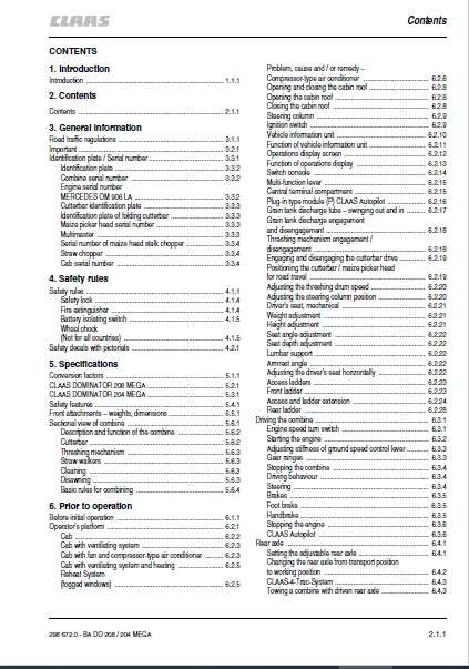
2 Contents
Contents 2 1 1
3 General information
Road traffic regulations 3 1 1
Important 3 2 1
Identification plate / Serial number 3 3 1
Identification plate 3 3 2
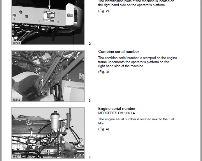
Combine serial number 3 3 2
Engine serial number
MERCEDES OM 906 LA 3 3 2
Cutterbar identification plate 3 3 3
Identification plate of folding cutterbar 3 3 3
Maize picker head serial number 3 3 3
Multimaster 3 3 3
Serial number of maize head stalk chopper 3 3 4
Straw chopper 3 3 4
Cab serial number 3 3 4
4 Safety rules
Safety rules 4 1 1
Safety lock 4 1 4
Fire extinguisher 4 1 4
Battery isolating switch 4 1 5
Wheel chock
(Not for all countries) 4 1 5
Safety decals with pictorials 4 2 1
5 Specifications
Conversion factors 5 1 1
CLAAS DOMINATOR 208 MEGA 5 2 1
CLAAS DOMINATOR 204 MEGA 5 3 1
Safety features 5 4 1
Front attachments – weights, dimensions 5 5 1
Sectional view of combine 5 6 1
Description and function of the combine 5 6 2
Cutterbar 5 6 2
Threshing mechanism 5 6 3
Straw walkers 5 6 3
Cleaning 5 6 3
Disawning 5 6 3
Basic rules for combining 5 6 4
6 Prior to operation
Before initial operation 6 1 1
Operator’s platform 6 2 1
Cab 6 2 2
Cab with ventilating system 6 2 3
Cab with fan and compressor-type air conditioner 6 2 3
Cab with ventilating system and heating 6 2 5
Reheat System
(fogged windows) 6 2 5
Problem, cause and / or remedy –
Compressor-type air conditioner 6 2 6
Opening and closing the cabin roof 6 2 8
Opening the cabin roof 6 2 8
Closing the cabin roof 6 2 8
Steering column 6 2 9
Ignition switch 6 2 9
Vehicle information unit 6 2 10
Function of vehicle information unit 6 2 11
Operations display screen 6 2 12
Function of operations display 6 2 13
Switch console 6 2 14
Multi-function lever 6 2 15
Central terminal compartment 6 2 15
Plug-in type module (P) CLAAS Autopilot 6 2 16
Grain tank discharge tube – swinging out and in 6 2 17
Grain tank discharge engagement
and disengagement 6 2 18
Threshing mechanism engagement /
disengagement 6 2 18
Engaging and disengaging the cutterbar drive 6 2 19
Positioning the cutterbar / maize picker head
for road travel 6 2 19
Adjusting the threshing drum speed 6 2 20
Adjusting the steering column position 6 2 20
Driver’s seat, mechanical 6 2 21
Weight adjustment 6 2 21
Height adjustment 6 2 21
Seat angle adjustment 6 2 22
Seat depth adjustment 6 2 22
Lumbar support 6 2 22
Armrest angle 6 2 22
Adjusting the driver’s seat horizontally 6 2 22
Access ladders 6 2 23
Front ladder 6 2 23
Access and ladder extension 6 2 24
Rear ladder 6 2 28
Driving the combine 6 3 1
Engine speed turn switch 6 3 1
Starting the engine 6 3 2
Adjusting stiffness of ground speed control lever 6 3 3
Gear ranges 6 3 3
Stopping the combine 6 3 4
Driving behaviour 6 3 4
Steering 6 3 4
Brakes 6 3 5
Foot brake 6 3 5
Handbrake 6 3 5
Stopping the engine 6 3 6
CLAAS Autopilot 6 3 6
Rear axle 6 4 1
Setting the adjustable rear axle 6 4 1
Changing the rear axle from transport position
to working position 6 4 2
CLAAS-4-Trac-System 6 4 3
Towing a combine with driven rear axle 6 4 3
Contents
2 1 2 BA DO 208 / 204 MEGA – 298 672 0
Contents
Cutterbar cylinders 6 5 1
Hydraulic cylinders 6 5 1
Attaching the cutterbar hydraulic cylinders 6 5 1
Attaching the right-hand cutterbar cylinder 6 5 1
Attaching a third cutterbar cylinder 6 5 2
Towing and side walk railing 6 6 1
Towing the combine 6 6 1
Forward 6 6 1
Backward 6 6 1
Side walk railing 6 6 2
Tilting the side walk railing 6 6 2
Cab and lighting 6 7 1
Cab 6 7 1
Driving lights, worklights and mirrors 6 7 1
7 Operation – cutterbar
Attaching the cutterbar 7 1 1
Adjusting the strippers
DOMINATOR MEGA 204 7 1 1
Machine with CLAAS Auto Contour 7 1 1
Levelling the coupling lug cylinders 7 1 3
Machine without Auto Contour 7 1 3
Levelling the cutterbar 7 1 4
Connecting the universal drive shafts
DOMINATOR 208 MEGA 7 1 5
Connecting the universal drive shafts
DOMINATOR 204 MEGA 7 1 5
Connecting hydraulic hoses 7 1 6
Connecting the cables 7 1 6
Installing the stands 7 1 7
Adjustments at the cutterbar 7 2 1
Dividers 7 2 1
Grain lifters 7 2 2
Knife 7 2 3
Removing the knife 7 2 3
Installing the knife 7 2 3
Adjusting the height of the knife head 7 2 4
Adjusting the knife clips 7 2 4
Spare knife 7 2 4
Cutterbar skids 7 2 5
Reel 7 2 5
Reel tines 7 2 6
Reel drive 7 2 6
Fore and aft reel adjustment
(mechanical) 7 2 7
Fore and aft reel adjustment
(hydraulic) 7 2 7
Reel variable speed drive 7 2 8
Main table auger 7 2 8
Adjust clearance to cutterbar trough 7 2 8
Adjusting position of auger fingers 7 2 9
Adjusting the stripper plates 7 2 9
Replacing knife sections in the field 7 2 10
8 Operation – basic machine
Feeder housing 8 1 1
Chains 8 1 1
Cutterbar reverse drive 8 1 2
CLAAS Auto Contour
Automatic cutting height control
and lateral levelling system 8 1 3
Cutterbar automatic pre-set height
(machines with Auto Contour) 8 1 5
Adjusting the cutterbar floatation springs 8 1 6
Checking the cutterbar floatation springs
and checking the feeder house suspension
for smooth movement 8 1 6
Setting the cutting height indicator 8 1 7
Cutterbar spring pressure indicator 8 1 7
Adjusting the cutterbar drop rate 8 1 8
Putting the CLAAS Auto Contour System
into operation 8 1 9
Operation with maize picker head 8 1 10
Programming the CLAAS Auto Contour System 8 1 10
Setting chart for automatic cutting height control 8 1 11
Putting the cutterbar automatic pre-set
height system into operation
(machines with Auto Contour) 8 1 12
CLAAS Contour System
(ground pressure control) 8 1 13
Setting the cutterbar ground pressure 8 1 14
Putting the CLAAS Contour System into operation 8 1 14
CLAAS cutterbar pre-set height 8 1 16
Putting the cutterbar pre-set height system
into operation 8 1 16
Cutterbar adjusting range 8 1 16
Clearance height 8 1 17
Cutterbar adjusting range without Auto Contour 8 1 17
Clearance height to underside of cutterbar skid 8 1 17
Cutterbar clutch 8 1 18
Engaging and disengaging the cutterbar 8 1 18
Threshing mechanism 8 2 1
Stone trap 8 2 1
Engaging and disengaging the threshing mechanism 8 2 1
Concave adjustment 8 2 2
Concave settings 8 2 3
Threshing drum 8 2 4
Cleaning dirty threshing parts 8 2 4
Threshing drum speed 8 2 5
Adjusting the threshing drum speed 8 2 6
Threshing drum speed display 8 2 6
Threshing drum two-step variable speed drive 8 2 6
Preconcave 8 2 7
Disawning 8 2 8
Threshing segment 8 2 9
Unslugging the threshing drum 8 2 10
Impeller 8 2 11
Deflector curtain 8 2 11
Straw walkers and cleaning 8 3 1
Straw walkers 8 3 1
Intensive separation system 8 3 1
Cleaning the straw walkers 8 3 2
Straw walker risers 8 3 2
Warning signal 8 3 4
Sieve pan 8 3 4
Preparation floor 8 3 5
298 672 0 – BA DO 208 / 204 MEGA 2 1 3
Contents
Cleaning fan 8 3 5
Electrical fan speed adjustment 8 3 6
Fan speed display 8 3 6
Ventilated straw walker step 8 3 7
Adjusting the butterfly valve 8 3 7
Adjusting the wind board 8 3 7
Sieves 8 3 8
Adjusting the frogmouth sieves 8 3 8
Hillside riser plates
(machines without 3-D cleaning system) 8 3 8
Lower sieves 8 3 8
Removing upper sieves 8 3 9
Installing upper sieves 8 3 9
Removing lower sieves 8 3 9
Installing lower sieves 8 3 9
Tightening torques of the axial bolts
for the upper and lower sieves 8 3 9
Dynamic sidehill levelling
(3-D cleaning system) 8 3 10
Returns 8 3 10
Combine performance monitor 8 3 12
Adjusting monitor to crop type 8 3 13
Adjusting sensitivity of sensors 8 3 13
Grain delivery 8 4 1
Augers and auger troughs 8 4 1
Elevators 8 4 1
Grain tank 8 4 2
Grain tank covers 8 4 2
Unloading the tank 8 4 3
Rear ladder with safety switch 8 4 4
Grain tank discharge auger 8 4 4
Grain tank discharge – engage and disengage 8 4 5
Clean-out door on grain tank discharge tube 8 4 6
Drive to grain tank discharge augers 8 4 6
Shear bolt – grain tank discharge 8 4 7
Lateral auger drive 8 4 7
Grain tank fill indicator 8 4 8
Acoustic grain tank fill indicator 8 4 8
Straw chopper / Chaff spreader 8 5 1
Straw chopper 8 5 1
Before using the straw chopper, check 8 5 1
Putting the straw chopper into operation 8 5 2
Adjusting spreading width 8 5 3
Electric deflector adjustment 8 5 3
Adjusting the deflectors 8 5 3
Adjusting the length of cut 8 5 4
Adjusting cross knife 8 5 4
Putting the straw chopper out of operation
and changing over to windrowing straw 8 5 5
Hitching the cutterbar trailer to the combine 8 5 6
Chaff spreader 8 5 6
Setting the chaff spreader 8 5 6
Sieve chart and suggested combine adjustments 8 6 1
Sieve chart 8 6 1
Suggested combine adjustments 8 6 2
Disawner plates 8 6 8
Threshing segment 8 6 8
Problem, cause and / or remedy – Basic machine 8 7 1
9 Maintenance – basic machine, cutterbar
Important maintenance instructions 9 1 1
Important maintenance instructions and safety rules 9 1 1
Maintenance schedules and lubricants charts 9 2 1
Maintenance schedules 9 2 1
Lubricants charts 9 2 4
Hydraulic system 9 3 1
Hydraulic accumulators 9 3 1
Checking the oil level
(Hydrostatic ground speed drive
and working hydraulics) 9 3 2
Changing hydraulic oil
(Hydrostatic ground speed drive
and working hydraulics)
Linde HPV 75 and HMF 105 9 3 2
Changing the hydraulic oil filter 9 3 3
Refilling the system after hydraulic oil change 9 3 4
Hydrostatic pump adjustment 9 3 4
Bleeding the reel cylinders 9 3 5
Bleeding the hydraulic cylinders
for cutterbar lateral levelling
(Machines with Auto Contour System) 9 3 6
Foot brake / brake fluid 9 3 7
Transmission and gearboxes 9 4 1
Gear shift control adjustment 9 4 1
Change-speed transmission gearbox 9 4 1
Checking oil level 9 4 1
Oil change 9 4 1
Final drives
DOMINATOR 208 MEGA 9 4 2
Checking oil level 9 4 2
Oil change 9 4 2
Final drives
DOMINATOR 204 MEGA 9 4 2
Checking oil level 9 4 2
Oil change 9 4 2
Rear wheel drive planetary gears
CLAAS 4-Trac System 9 4 3
Check oil level 9 4 3
Oil change 9 4 3
Knife drive casing 9 4 3
Checking the oil level / oil change 9 4 3
Threshing drum reduction gearbox 9 4 4
Checking oil level 9 4 4
Oil change 9 4 4
Grain tank 9 4 4
Angle drive on grain tank discharge auger 9 4 4
Angle drive on grain tank
(DOMINATOR 208 MEGA) 9 4 4
Feeder housing 9 5 1
Tension feeder chains 9 5 1
Elevator chains 9 6 1
Tension grain elevator chain 9 6 1
Tension returns elevator chain 9 6 2
Drive belts / drive chains – basic machine 9 7 1
General notes 9 7 1
Drive diagram left 9 7 2
Drive diagram right 9 7 3
2 1 4 BA DO 208 / 204 MEGA – 298 672 0
Contents
Drive belts / drive chains 9 7 4
Removing cutterbar drive belt (1) 9 7 4
Fitting and tensioning cutterbar drive belt (1) 9 7 5
Tensioning compressor drive belt (2) 9 7 6
Tensioning hydrostatic ground drive belt (3) 9 7 7
Tensioning working hydraulics pump drive belt (4) 9 7 8
Removing and installing the power band belt (3) 9 7 9
Threshing mechanism drive belt (5) 9 7 10
Removing and installing the threshing mechanism
drive belt (5) 9 7 11
Grain tank unloading drive belt (6) 9 7 13
Removing and installing the sieve pan drive belt (7) 9 7 14
Removing and fitting fan variable-speed belt (8) 9 7 15
Removing and installing the sieve pan drive belt (9) 9 7 16
Removing and installing the sieve pan
drive belt (10) 9 7 16
Removing and installing the straw walker
drive belt (11) 9 7 17
Removing and installing the intensive
separation system drive belt (12) 9 7 17
Removing and installing the chaff spreader
drive belt (15) 9 7 18
Chaff spreader drive belt (16) 9 7 18
Straw chopper intermediate drive belt (21) 9 7 19
Tensioning suction blower drive belt (22) 9 7 22
Removing and fitting threshing drum
variable speed drive belt (23) 9 7 22
Removing and filtting the threshing drum
drive belt (24) 9 7 24
Tensioning radiator screen intermediate
drive belt (27) 9 7 25
Tensioning the grain tank unloading
intermediate drive chain (31)
(DOMINATOR 208 MEGA) 9 7 25
Tensioning the grain tank unloading
intermediate drive chain (32)
(DOMINATOR 208 MEGA) 9 7 25
Tensioning the grain tank unloading
intermediate drive chain (31)
(DOMINATOR 204 MEGA) 9 7 26
Tensioning returns drive chain (33) 9 7 26
Removing and installing the accelerator
drive belt (17) 9 7 27
Straw chopper drive belt (20) 9 7 29
Drive belts / drive chains – cutterbar 9 8 1
General notes 9 8 1
Drive diagram cutterbar 9 8 2
Tensioning knife drive belt (40) 9 8 3
Tensioning main table auger drive chain (41) 9 8 3
Tensioning reel drive chain (42) 9 8 4
Removing and fitting reel drive belt (43) 9 8 4
Tensioning reel drive chain (44) 9 8 6
Tensioning reel drive chain (45) 9 8 6
Cab / Compressor-type air conditioner 9 9 1
Cab 9 9 1
Cleaning the filters 9 9 1
Compressor-type air conditioner 9 9 1
Cleaning the condenser 9 9 1
Checking refrigerant level 9 9 2
Replacing the filter receiver drier 9 9 2
Required refrigerant quantity – Refrigerant R 134 a 9 9 2
Maintenance work before the harvest 9 9 3
Fire extinguisher 9 10 1
Have fire extinguisher checked
for serviceable condition 9 10 1
Speeds 9 11 1
Checking the speed of the straw walker shaft 9 11 1
Setting the magnetic pick-ups 9 11 1
Machines equipped with fieldwork computer 9 11 1
Straw chopper 9 12 1
Changing the free-swinging knives 9 12 1
Removing knives 9 12 1
Installing knives 9 12 2
Changing the fixed stationary knives 9 12 2
Winter storage instructions for combines 9 13 1
10 Maintenance – engine
Important maintenance instructions 10 1 1
Important maintenance instructions
and safety rules 10 1 1
Maintenance schedules and lubricants charts 10 2 1
Maintenance schedule 10 2 1
Lubricants chart 10 2 2
Maintenance – engine 10 3 1
Engine overview 10 3 1
Fuel feed system 10 3 1
Fuel tank 10 3 2
Fuel shut-off tap 10 3 2
Water separator / fuel prefilter
(extra equipment – small version) 10 3 3
Fuel prefilter 10 3 3
Water separator / fuel prefilter
(extra equipment – large version) 10 3 4
Fuel filter 10 3 5
Bleeding the fuel system 10 3 5
Checking engine oil level 10 3 5
Engine oil change 10 3 6
Draining the old oil 10 3 6
Oil filter 10 3 7
Filling in engine oil 10 3 7
Tensioning the alternator belt 10 3 7
Cooling system 10 4 1
Coolant 10 4 1
Water drain plugs on the engine block 10 4 1
Water cooler 10 4 1
Filling the cooling system with coolant 10 4 2
Overpressure 10 4 2
Antifreeze / corrosion protection 10 4 2
Warning notice 10 4 3
Cooling water temperature 10 4 3
Radiator chaff screen 10 4 3
Cleaning the radiator chaff screen 10 4 3
Folding up radiator chaff screen 10 4 3
Swinging up the oil cooler 10 4 4
Clean water cooler and intercooler 10 4 5
Dry-type air cleaner 10 5 1
Warning device 10 5 1
298 672 0 – BA DO 208 / 204 MEGA 2 1 5
Contents
Cleaning the air cleaner intake screen 10 5 1
Cleaning the air cleaner 10 5 1
Cleaning the dry-type air cleaner
with dust extractor unit 10 5 2
Removing the main filter cartridge 10 5 3
Installing the main filter cartridge 10 5 4
Safety cartridge 10 5 4
Electrical equipment 10 6 1
Battery 10 6 1
Alternator 10 6 2
Engine problems, cause and / or remedy 10 7 1
Engine winter storage 10 8 1
Engine preservation 10 8 1
11 Lubrication chart
Lubricants and lubrication instructions 11 1 1
12 Index
Index 12 1 1
IMAGES PREVIEW OF THE MANUAL:
CLAAS DOMINATOR 208 MEGA III DOMINATOR 204 MEGA III OPERATOR’S MANUAL – PDF DOWNLOAD:
PLEASE NOTE:
- This is the SAME manual used by the dealers to troubleshoot any faults in your vehicle. This can be yours in 2 minutes after the payment is made.
- Contact us at [email protected] should you have any queries before your purchase or that you need any other service / repair / parts operators manual.
S.V