CLAAS FOLDING CUTTERBAR 4.50-5.40 M LEXION Service Manual PDF
Original price was: $78.00.$26.95Current price is: $26.95.
CLAAS FOLDING CUTTERBAR 4.50 M – 5.40 M LEXION Repair manual – PDF DOWNLOAD
Description
CLAAS FOLDING CUTTERBAR 4.50 M – 5.40 M LEXION Repair manual – PDF DOWNLOAD
DESCRIPTION:
CLAAS FOLDING CUTTERBAR 4.50 M – 5.40 M LEXION Repair manual – PDF DOWNLOAD
Introduction
- This CLAAS REPAIR MANUAL is to assist in preserving the permanent working order and therefore the high value of your CLAAS machine by careful maintenance and service. Experience gathered by both our service engineers and factory staff has been compiled in this REPAIR MANUAL.
- The figures explain the procedure of repairs and the text describes the different adjustments to be made, the use of CLAAS special tools etc. The illustrations included in support to the explanations show the sequence of major repairs so that minor repairs can easily be followed.
- The CLAAS REPAIR MANUAL is filled in a folder which allows to insert supplementary pages as issued following technical developments and to always have an updated manual at hand for reference.
- To be sure, always compare settings and filling capacities with specifications stated in the current Operator’s Manual which applies to the combine-harvester
TABLE OF CONTENTS:
CLAAS FOLDING CUTTERBAR 4.50 M – 5.40 M LEXION Repair manual – PDF DOWNLOAD
1 Introduction
General 111
Introduction 111
Introduction to the CLAAS Repair Manual 112
Key to symbols 113
Safety Rules 121
Important information 121
Identification of warning and danger signs 122
Correct use of the cutterbar 122
General safety and accident prevention regulations 122
Leaving the machine 122
Service 123
Basic rule 123
Hydraulic accumulators 123
General repair information 131
Reason of damage 131
Spare parts 131
Transmission 131
Tensioning the steel roller chains 131
Taper ring fasteners 131
Self-locking bolts 131
Liquid locking compound 131
Correct installation of lock collar bearings 132
Correct installation of adapter sleeve bearings 132
Ferrule fittings on hydraulic lines 132
Progressive ring fittings on hydraulic lines 132
Taper fittings on hydraulic lines 133
Welding 133
Some advice for speedy and correct repair work 133
Tightening torques 141
Bolts 141
Hydraulic screw fittings 142
Specifications 151
Lubricants chart 151
Drive diagram 161
General information on drives 161
Drive diagram, left-hand 161
Drive diagram, right-hand 162
2 Crop dividers
Crop dividers 211
Removing the long / short crop dividers 211
Installing the long / short crop dividers 211
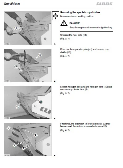
Removing the special crop dividers 212
Special crop divider, disassembled 213
Installing the special crop divider 214
3 Cutterbar trough – Cutter bar
Cutter bar 311
Removing the knife 311
Installing the knife 311
Adjusting the knife height 312
Cutterbar lock
(mechanical) 321
Removing the mechanical cutterbar lock 321
Mechanical cutterbar lock, disassembled 323
Installing the mechanical cutterbar lock 324
Rotating arm 331
Removing the rotating arm 331
Rotating arm, disassembled 334
Installing the rotating arm 335
Folding unit 341
Removing the cutterbar fold hydraulic cylinder rack 341
Cutterbar fold hydraulic cylinder rack, disassembled 343
Installing the cutterbar fold hydraulic cylinder rack 344
4 Drives
Intermediate drive 411
Removing the left-hand intermediate drive shaft 411
Left-hand intermediate drive, disassembled 412
Installing the left-hand intermediate drive shaft 413
Removing the right-hand intermediate drive shaft 414
Right-hand intermediate drive, disassembled 416
Installing the right-hand intermediate drive shaft 416
Main drive universal drive shaft 421
Removing the main drive universal drive shaft 421
Disassembling the main drive universal drive shaft 422
Main drive universal drive shaft, disassembled 424
Assembling the main drive universal drive shaft 425
Mounting the main drive universal drive shaft 426
Knife drive 431
Removing the knife drive belt (44) 431
Installing and adjusting the knife drive
belt (44) 433
Removing the knife drive belt (51) 435
Installing and adjusting the knife drive
belt (51) 437
Removing the jockey pulley of knife drive
belt (44) and/or (51) 437
Knife drive belt (44), disassembled 439
Knife drive belt (51), disassembled 4310
Installing the jockey pulley of knife drive
belt (44) and/or (51) 4311
Removing the deflection pulley of
knife drive belt (44) and/or (51) 4312
Installing the deflection pulley of
knife drive belt (44) and/or (51) 4312
Wobble transmission 441
Removing the wobble transmission
(Part nos 643 6862 and 643 6562) 441
Disassembling the wobble transmission
(Part nos 643 6862 and 643 6562) 443
Wobble transmission, disassembled
(Part no 643 6862) 447
Wobble transmission, disassembled
(Part no 643 6562) 448
Assembling the wobble transmission
(Spare part nos 643 6862 and 643 6562) 449
Installing the wobble transmission
(Spare part nos 643 6862 and 643 6562) 4417
5 Intake auger
Intake auger drive 511
Removing the feed drive chain (40) 511
Contents
012 RHB klappbares SW 4,50 m – 5,40 m LEXION – 299 2110
Contents
Installing and adjusting the feed drive
chain (40) 512
Removing and disassembling the jockey
sprocket of feed drive chain (40) and/or (50) 512
Installing the jockey sprocket of
feed drive chain (40) and /or (50) 512
Removing and installing the double sprocket
of feed drive chain (40) and/or (50) 513
Removing the intake auger slip clutch 513
Intake auger slip clutch, disassembled
(left-hand machine side) 515
Installing the intake auger slip clutch 516
Removing the feed drive chain (50) 519
Installing and adjusting the feed drive
chain (50) 5110
Intake auger slip clutch, disassembled
(right-hand machine side) 5111
Intake auger 521
Removing the left-hand (outside) and/or
right-hand (outside) intake auger bearing 521
Left-hand (outside) and/or right-hand (outside)
intake auger bearing, disassembled 522
Installing the left-hand (outside) and/or
right-hand (outside) intake auger bearing 523
Removing the left-hand and/or right-hand
intake auger drive shaft 527
Installing the left-hand and/or right-hand
intake auger drive shaft 528
Removing the left-hand (centre) and/or
right-hand (centre) intake auger bearing 528
Left-hand (centre) and/or right-hand (centre)
intake auger bearing, disassembled 5211
Installing the left-hand (centre) and/or
right-hand (centre) intake auger bearing 5211
Left-hand intake auger, disassembled 5217
Right-hand intake auger, disassembled 5219
Removing the intake auger finger 5220
Installing the intake auger finger 5221
Removing the control shafts 5222
Removing the control shafts
(up to serial no …) 5223
Control shafts, disassembled
(up to serial no …) 5225
Removing the control shafts
(from serial no …) 5225
Control shafts, disassembled
(from serial no …) 5227
Installing the control shafts
(from serial no …, up to serial no …) 5227
6 Reel
Reel drive 611
Removing the drive chain (41) 611
Installing and adjusting the drive chain (41) 612
Removing the top sprocket of drive chain (41) 612
Installing the top sprocket of drive chain (41) 612
Removing the reel drive belt (42) 613
Installing and adjusting the reel drive belt (42) 614
Removing the variable-speed pulleys
of reel drive (42) 614
Installing the variable-speed pulleys
of reel drive (42) 614
Removing the drive chain (43) 614
Installing and adjusting the drive chain (43) 614
Removing the top sprocket of drive chain (43) 615
Installing the top sprocket of drive chain (43) 615
Removing the bottom sprocket of
drive chain (43) 615
Installing the bottom sprocket of
drive chain (43) 615
Removing the sprocket of drive chain (43) 616
Installing the sprocket of drive chain (43) 616
Removing the reel drive slip clutch 616
Disassembling the reel drive slip clutch 617
Reel drive slip clutch, disassembled
(up to serial no …) 618
Reel drive slip clutch, disassembled
(from serial no …) 619
Assembling the reel drive slip clutch 6111
Installing the reel drive slip clutch 6112
Removing the reel drive shaft (17) 6113
Installing the reel drive shaft (17) 6114
Removing the reel drive dog clutch 6115
Reel drive dog clutch, disassembled 6117
Installing the reel drive dog clutch 6118
Reel drive universal drive shaft 621
Removing the reel drive universal drive shaft 621
Disassembling the reel drive universal drive shaft 622
Reel drive universal drive shaft, disassembled 624
Assembling the reel drive universal drive shaft 625
Mounting the reel drive universal drive shaft 626
Reel drive angle drive 631
Removing the rear angle drive 631
Disassembling the rear angle drive 632
Assembling the rear angle drive 634
Mounting the rear angle drive 635
Removing the front angle drive 636
Disassembling the front angle drive 637
Front angle drive, disassembled 6310
Assembling the front angle drive 6311
Mounting the front angle drive 6314
Reel speed adjustment 641
Removing the electric reel variable-speed pulley 641
Reel variable-speed drive, disassembled 643
Mounting the electric reel variable-speed pulley 644
Removing the spring-loaded
reel variable-speed pulley 646
Spring-loaded reel variable-speed pulley,
disassembled 648
Mounting the spring-loaded
reel variable-speed pulley 649
Removing the reel variable-speed drive
bearing tube 6410
Reel variable-speed drive bearing tube,
disassembled 6411
299 2110 – RHB klappbares SW 4,50 m – 5,40 m LEXION 013
Contents
Installing the reel variable-speed drive
bearing tube 6412
Removing the electric reel speed adjustment 6413
Disassembling the electric reel speed adjustment 6416
Electric reel speed adjustment, disassembled 6418
Assembling the electric reel speed adjustment 6419
Mounting the electric reel speed adjustment 6421
Left-hand reel 651
Removing the left-hand reel 651
Left-hand reel, disassembled 653
Installing the left-hand reel 654
Removing the left-hand reel bearing
(Left-hand reel) 654
Installing the left-hand reel bearing
(Left-hand reel) 655
Removing the control rollers
(Left-hand reel) 655
Installing the control rollers
(Left-hand reel) 656
Removing the control spider
(Left-hand reel) 656
Installing the control spider
(Left-hand reel) 657
Removing the left-hand reel spider
(Left-hand reel) 657
Installing the left-hand reel spider
(Left-hand reel) 658
Removing the right-hand reel bearing
(Left-hand reel) 659
Installing the right-hand reel bearing
(Left-hand reel) 6510
Checking the reel lock setting 6511
Removing the right-hand reel spider
(Left-hand reel) 6511
Installing the right-hand reel spider
(Left-hand reel) 6512
Removing the centre reel spider
(Left-hand reel) 6512
Installing the centre reel spider
(Left-hand reel) 6513
Right-hand reel 661
Removing the right-hand reel 661
Right-hand reel, disassembled 663
Installing the right-hand reel 664
Checking the pawl setting
(Reel lock) 664
Removing the right-hand reel bearing
(Right-hand reel) 665
Installing the right-hand reel bearing
(Right-hand reel) 665
Removing the control rollers
(Right-hand reel) 666
Installing the control rollers
(Right-hand reel) 666
Removing the control spider
(Right-hand reel) 666
Installing the control spider
(Right-hand reel) 667
Removing the right-hand reel spider
(Right-hand reel) 668
Installing the right-hand reel spider
(Right-hand reel) 669
Removing the left-hand reel bearing
(Right-hand reel) 669
Installing the left-hand reel bearing
(Right-hand reel) 6610
Removing the left-hand reel spider
(Right-hand reel) 6610
Installing the left-hand reel spider
(Right-hand reel) 6611
Removing the centre reel spider
(Right-hand reel) 6611
Installing the centre reel spider
(Right-hand reel) 6612
7 Hydraulic system / Electric system
Control valves 711
Removing the reel raise / lower valve block
with check valve 711
Reel raise / lower valve block with check valve,
disassembled 713
Assembling and installing the reel raise / lower
valve block with check valve 714
Removing the reel raise 3/2-way valve (Y22) 714
Reel raise 3/2-way valve (Y22), disassembled 715
Installing the reel raise 3/2-way valve (Y22) 716
Removing the 2/2-way check valve (Y69) 717
Installing the 2/2-way check valve (Y69) 717
Removing the reel lower 2/2-way valve (Y23) 717
Reel lower 2/2-way valve (Y23), disassembled 718
Installing the reel lower 2/2-way valve (Y23) 719
Removing the reel forward / backward
and cutterbar fold valve block 7110
Reel forward / backward and cutterbar fold
valve block, disassembled 7112
Assembling and installing the reel forward /
backward and cutterbar fold valve block 7113
Disassembling the reel forward / backward
and cutterbar fold valve block 7114
Removing the lock-up valve unit of
reel backward valve (Y25) 7115
Disassembling the lock-up valve unit
of reel backward valve (Y25) 7116
Lock-up valve unit of reel backward valve (Y25),
disassembled 7116
Assembling the lock-up valve unit
of reel backward valve (Y25) 7116
Installing the lock-up valve unit
of reel backward valve (Y25) 7117
Removing the pilot controlled non-return valve 7117
Disassembling the pilot controlled non-return valve 7118
Pilot controlled non-return valve, disassembled 7119
Assembling the pilot controlled non-return valve 7120
Installing and adjusting the pilot controlled
non-return valve 7121
Hydraulic cylinders 721
Removing the cutterbar fold hydraulic cylinder 721
014 RHB klappbares SW 4,50 m – 5,40 m LEXION – 299 2110
Contents
Disassembling the cutterbar fold hydraulic cylinder 722
Cutterbar fold hydraulic cylinder, disassembled 725
Assembling the cutterbar fold hydraulic cylinder 726
Installing the cutterbar fold hydraulic cylinder 729
Adjusting the cutterbar fold hydraulic cylinder 729
Removing the working position lock
hydraulic cylinder 7210
Disassembling the working position lock
hydraulic cylinder 7212
Working position lock hydraulic cylinder,
disassembled 7213
Assembling the working position lock
hydraulic cylinder 7214
Installing the working position lock
hydraulic cylinder 7216
Removing the transport position lock
hydraulic cylinder 7217
Disassembling the transport position lock
hydraulic cylinder 7218
Transport position lock hydraulic cylinder,
disassembled 7220
Assembling the transport position lock
hydraulic cylinder 7221
Installing the transport position lock
hydraulic cylinder 7223
Removing the left-hand single-acting
reel height adjustment hydraulic cylinder 7224
Disassembling the left-hand single-acting
reel height adjustment hydraulic cylinder 7224
Left-hand single-acting reel height adjustment
hydraulic cylinder, disassembled 7226
Assembling the left-hand single-acting
reel height adjustment hydraulic cylinder 7227
Installing the left-hand single-acting
reel height adjustment hydraulic cylinder 7229
Removing the right-hand double-acting
reel height adjustment hydraulic cylinder 7230
Disassembling the right-hand double-acting
reel height adjustment hydraulic cylinder 7230
Right-hand double-acting reel height adjustment
hydraulic cylinder, disassembled 7232
Assembling the right-hand double-acting
reel height adjustment hydraulic cylinder 7233
Installing the right-hand double-acting
reel height adjustment hydraulic cylinder 7235
Removing the left-hand fore and aft
reel adjustment hydraulic cylinder 7236
Disassembling the left-hand fore and aft
reel adjustment hydraulic cylinder 7236
Left-hand fore and aft reel adjustment
hydraulic cylinder, disassembled 7238
Assembling the left-hand fore and aft
reel adjustment hydraulic cylinder 7239
Installing the left-hand fore and aft reel
adjustment hydraulic cylinder 7241
Removing the centre fore and aft
reel adjustment hydraulic cylinder 7242
Disassembling the centre fore and aft
reel adjustment hydraulic cylinder 7242
Centre fore and aft reel adjustment
hydraulic cylinder, disassembled 7244
Assembling the centre fore and aft
reel adjustment hydraulic cylinder 7245
Installing the centre fore and aft
reel adjustment hydraulic cylinder 7247
Removing the right-hand fore and aft
reel adjustment hydraulic cylinder 7248
Disassembling the right-hand fore and aft
reel adjustment hydraulic cylinder 7248
Right-hand fore and aft reel adjustment
hydraulic cylinder, disassembled 7250
Assembling the right-hand fore and aft
reel adjustment hydraulic cylinder 7251
Installing the right-hand fore and aft
reel adjustment hydraulic cylinder 7253
Potentiometers 731
Replacing the CAC sensing band potentiometer 731
Adjusting the CAC potentiometer 733
Replacing the automatic reel height
adjustment potentiometer 733
Adjusting the automatic reel height
adjustment potentiometer 735
Adjusting the cutterbar lock limit switch 736
Adjusting the reel drive universal drive shaft
limit switch 737
Adjusting the reel limit switch 738
Folding procedure
(Description of function) 741
Folding from transport position to working position 741
Folding from working position to transport position 745
7 Index
IMAGES PREVIEW OF THE MANUAL:
CLAAS FOLDING CUTTERBAR 4.50 M – 5.40 M LEXION REPAIR MANUAL – PDF DOWNLOAD:
PLEASE NOTE:
- This is not a physical manual but a digital manual – meaning no physical copy will be couriered to you. The manual can be yours in the next 2 mins as once you make the payment, you will be directed to the download page IMMEDIATELY.
- This is the same manual used by the dealers inorder to diagnose your vehicle of its faults.
- Require some other service manual or have any queries: please WRITE to us at [email protected]
- SM