CLAAS FOLDING CUTTERBAR 4.50 M – 5.40 M LEXION REPAIR MANUAL – PDF DOWNLOAD
Original price was: $89.00.$28.95Current price is: $28.95.
CLAAS FOLDING CUTTERBAR 4.50 M – 5.40 M LEXION REPAIR MANUAL – PDF DOWNLOAD
Description
CLAAS FOLDING CUTTERBAR 4.50 M – 5.40 M LEXION REPAIR MANUAL – PDF DOWNLOAD
DESCRIPTION:
CLAAS FOLDING CUTTERBAR 4.50 M – 5.40 M LEXION REPAIR MANUAL – PDF DOWNLOAD
Introduction
- This CLAAS REPAIR MANUAL is to assist in preserving the permanent working order and therefore the high value of your CLAAS machine by careful maintenance and service.
- Experience gathered by both our service engineers and factory staff has been compiled in this REPAIR MANUAL.
- The figures explain the procedure of repairs and the text describes the different adjustments to be made, the use of CLAAS special tools etc.
- The illustrations included in support to the explanations show the sequence of major repairs so that minor repairs can easily be followed.
- The CLAAS REPAIR MANUAL is filled in a folder which allows to insert supplementary pages as issued following technical developments and to always have an updated manual at hand for reference.
- To be sure, always compare settings and filling capacities with specifications stated in the current Operator’s Manual which applies to the combine-harvester.
Introduction to the CLAAS Repair Manual
- The CLAAS REPAIR MANUAL is divided into main groups and subgroups. The first figure at the bottom of each page refers to the main group whereas the second figure following the point indicates the subgroup; the figure behind the second point indicates the page number.
- In each subgroup, the figures and pages are numbered consecutively, starting at 1. Where differences between the machine types must be observed, this is indicated in headings.
- Where a service procedure applies to all machines covered by this book, the machine names are not specifically given. When supplements are to be added, the subgroups are supplemented or exchanged.
- All supplements are inserted into the respective main group / subgroup and the table of contents is updated. The symbols communicate brief messages when recurring service procedures are described. Their meaning is explained at the beginning of this manual.
- The section “GENERAL REPAIR INSTRUCTIONS” at the beginning of this manual contains useful practical hints. Read and follow these fundamental instructions.
- They are the basis for reliable service and durability of parts after repairs have been carried out. The description of a particular service procedure can easily be found by checking the table of contents of the appropriate main group / subgroup.
TABLE OF CONTENTS:
CLAAS FOLDING CUTTERBAR 4.50 M – 5.40 M LEXION REPAIR MANUAL – PDF DOWNLOAD
Contents 3
Introduction 7
General 9
Introduction 9
Introduction to the CLAAS Repair Manual 10
Key to symbols 11
Safety Rules 13
Important information 13
Identification of warning and danger signs 14
Correct use of the cutterbar 14
General safety and accident prevention regulations 14
Leaving the machine 14
Service 15
Basic rule 15
Hydraulic accumulators 15
General repair information 17
Reason of damage 17
Spare parts 17
Transmission 17
Tensioning the steel roller chains 17
Taper ring fasteners 17
Self-locking bolts 17
Liquid locking compound 17
Correct installation of lock collar bearings 18
Correct installation of adapter sleeve bearings 18
Ferrule fittings on hydraulic lines 18
Progressive ring fittings on hydraulic lines 18
Taper fittings on hydraulic lines 19
Welding 19
Some advice for speedy and correct repair work: 19
Tightening torques 21
Bolts 21
Hydraulic screw fittings 22
Specifications 23
Lubricants chart 23
Drive diagram 25
General information on drives 25
Drive diagram, left-hand 25
Drive diagram, right-hand 26
Crop dividers 27
Crop dividers 29
Removing the long / short crop dividers 29
Installing the long / short crop dividers 29
Removing the special crop dividers 30
Special crop divider, disassembled 31
Installing the special crop divider 32
Cutterbar trough – Cutter bar 33
Cutter bar 35
Removing the knife 35
Installing the knife 35
Adjusting the knife height 36
Cutterbar lock (mechanical) 37
Removing the mechanical cutterbar lock 37
Mechanical cutterbar lock, disassembled 39
Installing the mechanical cutterbar lock 40
Rotating arm 43
Removing the rotating arm 43
Rotating arm, disassembled 46
Installing the rotating arm 47
Folding unit 51
Removing the cutterbar fold hydraulic cylinder rack 51
Cutterbar fold hydraulic cylinder rack, disassembled 53
Installing the cutterbar fold hydraulic cylinder rack 54
Drives 57
Intermediate drive 59
Removing the left-hand intermediate drive shaft 59
Left-hand intermediate drive, disassembled 60
Installing the left-hand intermediate drive shaft 61
Removing the right-hand intermediate drive shaft 62
Right-hand intermediate drive, disassembled 64
Installing the right-hand intermediate drive shaft 64
Main drive universal drive shaft 67
Removing the main drive universal drive shaft 67
Disassembling the main drive universal drive shaft 68
Main drive universal drive shaft, disassembled: 70
Assembling the main drive universal drive shaft 71
Mounting the main drive universal drive shaft 72
Knife drive 73
Removing the knife drive belt (44) 73
Installing and adjusting the knife drive belt (44) 75
Removing the knife drive belt (51) 77
Installing and adjusting the knife drive belt (51) 79
Removing the jockey pulley of knife drive belt (44) and/or (51) 79
Knife drive belt (44), disassembled 81
Knife drive belt (51), disassembled 82
Installing the jockey pulley of knife drive belt (44) and/or (51) 83
Removing the deflection pulley of knife drive belt (44) and/or (51) 84
Installing the deflection pulley of knife drive belt (44) and/or (51) 84
Wobble transmission 85
Removing the wobble transmission (Part nos 643 6862 and 643 6562) 85
Disassembling the wobble transmission (Part nos 643 6862 and 643 6562) 87
Wobble transmission, disassembled: (Part no 643 6862) 91
Wobble transmission, disassembled: (Part no 643 6562) 92
Assembling the wobble transmission (Spare part nos 643 6862 and 643 6562) 93
Installing the wobble transmission (Spare part nos 643 6862 and 643 6562)101
Intake auger105
Intake auger drive107
Removing the feed drive chain (40)107
Installing and adjusting the feed drive chain (40)108
Removing and disassembling the jockey sprocket of feed drive chain (40) and/or (50)108
Installing the jockey sprocket of feed drive chain (40) and /or (50)108
Removing and installing the double sprocket of feed drive chain (40) and/or (50)109
Removing the intake auger slip clutch109
Intake auger slip clutch, disassembled (left-hand machine side)111
Installing the intake auger slip clutch112
Removing the feed drive chain (50)115
Installing and adjusting the feed drive chain (50)116
Intake auger slip clutch, disassembled (right-hand machine side)117
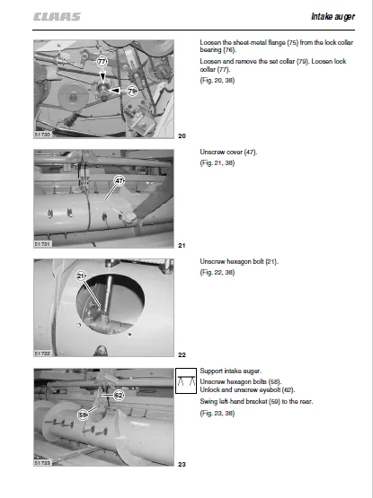
Intake auger119
Removing the left-hand (outside) and/or right-hand (outside) intake auger bearing119
Left-hand (outside) and/or right-hand (outside) intake auger bearing, disassembled:120
Installing the left-hand (outside) and/or right-hand (outside) intake auger bearing121
Removing the left-hand and/or right-hand intake auger drive shaft125
Installing the left-hand and/or right-hand intake auger drive shaft126
Removing the left-hand (centre) and/or right-hand (centre) intake auger bearing126
Left-hand (centre) and/or right-hand (centre) intake auger bearing, disassembled129
Installing the left-hand (centre) and/or right-hand (centre) intake auger bearing129
Left-hand intake auger, disassembled:135
Right-hand intake auger, disassembled:137
Removing the intake auger finger138
Installing the intake auger finger139
Removing the control shafts140
Removing the control shafts (up to serial no …)141
Control shafts, disassembled: (up to serial no …)143
Removing the control shafts (from serial no …)143
Control shafts, disassembled: (from serial no …:)145
Installing the control shafts (from serial no …, up to serial no …)145
Reel151
Reel drive153
Removing the drive chain (41)153
Installing and adjusting the drive chain (41)154
Removing the top sprocket of drive chain (41)154
Installing the top sprocket of drive chain (41)154
Removing the reel drive belt (42)155
Installing and adjusting the reel drive belt (42)156
Removing the variable-speed pulleys of reel drive (42)156
Installing the variable-speed pulleys of reel drive (42)156
Removing the drive chain (43)156
Installing and adjusting the drive chain (43)156
Removing the top sprocket of drive chain (43)157
Installing the top sprocket of drive chain (43)157
Removing the bottom sprocket of drive chain (43)157
Installing the bottom sprocket of drive chain (43)157
Removing the sprocket of drive chain (43)158
Installing the sprocket of drive chain (43)158
Removing the reel drive slip clutch158
Disassembling the reel drive slip clutch159
Reel drive slip clutch, disassembled: (up to serial no …)160
Reel drive slip clutch, disassembled: (from serial no …)161
Assembling the reel drive slip clutch163
Installing the reel drive slip clutch164
Removing the reel drive shaft (17)165
Installing the reel drive shaft (17)166
Removing the reel drive dog clutch167
Reel drive dog clutch, disassembled169
Installing the reel drive dog clutch170
Reel drive universal drive shaft171
Removing the reel drive universal drive shaft171
Disassembling the reel drive universal drive shaft172
Reel drive universal drive shaft, disassembled:174
Assembling the reel drive universal drive shaft175
Mounting the reel drive universal drive shaft176
Reel drive angle drive179
Removing the rear angle drive179
Disassembling the rear angle drive180
Assembling the rear angle drive182
Mounting the rear angle drive183
Removing the front angle drive184
Disassembling the front angle drive185
Front angle drive, disassembled:188
Assembling the front angle drive189
Mounting the front angle drive192
Reel speed adjustment193
Removing the electric reel variable-speed pulley193
Reel variable-speed drive, disassembled195
Mounting the electric reel variable-speed pulley196
Removing the spring-loaded reel variable-speed pulley198
Spring-loaded reel variable-speed pulley, disassembled200
Mounting the spring-loaded reel variable-speed pulley201
Removing the reel variable-speed drive bearing tube202
Reel variable-speed drive bearing tube, disassembled203
Installing the reel variable-speed drive bearing tube204
Removing the electric reel speed adjustment205
Disassembling the electric reel speed adjustment208
Electric reel speed adjustment, disassembled:210
Assembling the electric reel speed adjustment211
Mounting the electric reel speed adjustment213
Left-hand reel215
Removing the left-hand reel215
Left-hand reel, disassembled217
Installing the left-hand reel218
Removing the left-hand reel bearing (Left-hand reel)218
Installing the left-hand reel bearing (Left-hand reel)219
Removing the control rollers (Left-hand reel)219
Installing the control rollers (Left-hand reel)220
Removing the control spider (Left-hand reel)220
Installing the control spider (Left-hand reel)221
Removing the left-hand reel spider (Left-hand reel)221
Installing the left-hand reel spider (Left-hand reel)222
Removing the right-hand reel bearing (Left-hand reel)223
Installing the right-hand reel bearing (Left-hand reel)224
Checking the reel lock setting225
Removing the right-hand reel spider (Left-hand reel)225
Installing the right-hand reel spider (Left-hand reel)226
Removing the centre reel spider (Left-hand reel)226
Installing the centre reel spider (Left-hand reel)227
Right-hand reel229
Removing the right-hand reel229
Right-hand reel, disassembled231
Installing the right-hand reel232
Checking the pawl setting (Reel lock)232
Removing the right-hand reel bearing (Right-hand reel)233
Installing the right-hand reel bearing (Right-hand reel)233
Removing the control rollers (Right-hand reel)234
Installing the control rollers (Right-hand reel)234
Removing the control spider (Right-hand reel)234
Installing the control spider (Right-hand reel)235
Removing the right-hand reel spider (Right-hand reel)236
Installing the right-hand reel spider (Right-hand reel)237
Removing the left-hand reel bearing (Right-hand reel)237
Installing the left-hand reel bearing (Right-hand reel)238
Removing the left-hand reel spider (Right-hand reel)238
Installing the left-hand reel spider (Right-hand reel)239
Removing the centre reel spider (Right-hand reel)239
Installing the centre reel spider (Right-hand reel)240
Hydraulic system / Electric system241
Control valves243
Removing the reel raise / lower valve block with check valve243
Reel raise / lower valve block with check valve, disassembled245
Assembling and installing the reel raise / lower valve block with check valve246
Removing the reel raise 3/2-way valve (Y22)246
Reel raise 3/2-way valve (Y22), disassembled247
Installing the reel raise 3/2-way valve (Y22)248
Removing the 2/2-way check valve (Y69)249
Installing the 2/2-way check valve (Y69)249
Removing the reel lower 2/2-way valve (Y23)249
Reel lower 2/2-way valve (Y23), disassembled250
Installing the reel lower 2/2-way valve (Y23)251
Removing the reel forward / backward and cutterbar fold valve block252
Reel forward / backward and cutterbar fold valve block, disassembled:254
Assembling and installing the reel forward / backward and cutterbar fold valve block255
Disassembling the reel forward / backward and cutterbar fold valve block256
Removing the lock-up valve unit of reel backward valve (Y25)257
Disassembling the lock-up valve unit of reel backward valve (Y25)258
Lock-up valve unit of reel backward valve (Y25), disassembled:258
Assembling the lock-up valve unit of reel backward valve (Y25)258
Installing the lock-up valve unit of reel backward valve (Y25)259
Removing the pilot controlled non-return valve259
Disassembling the pilot controlled non-return valve260
Pilot controlled non-return valve, disassembled:261
Assembling the pilot controlled non-return valve262
Installing and adjusting the pilot controlled non-return valve263
Hydraulic cylinders265
Removing the cutterbar fold hydraulic cylinder265
Disassembling the cutterbar fold hydraulic cylinder266
Cutterbar fold hydraulic cylinder, disassembled:269
Assembling the cutterbar fold hydraulic cylinder270
Installing the cutterbar fold hydraulic cylinder273
Adjusting the cutterbar fold hydraulic cylinder273
Removing the working position lock hydraulic cylinder274
Disassembling the working position lock hydraulic cylinder276
Working position lock hydraulic cylinder, disassembled:277
Assembling the working position lock hydraulic cylinder278
Installing the working position lock hydraulic cylinder280
Removing the transport position lock hydraulic cylinder281
Disassembling the transport position lock hydraulic cylinder282
Transport position lock hydraulic cylinder, disassembled:284
Assembling the transport position lock hydraulic cylinder285
Installing the transport position lock hydraulic cylinder287
Removing the left-hand single-acting reel height adjustment hydraulic cylinder288
Disassembling the left-hand single-acting reel height adjustment hydraulic cylinder288
Left-hand single-acting reel height adjustment hydraulic cylinder, disassembled:290
Assembling the left-hand single-acting reel height adjustment hydraulic cylinder291
Installing the left-hand single-acting reel height adjustment hydraulic cylinder293
Removing the right-hand double-acting reel height adjustment hydraulic cylinder294
Disassembling the right-hand double-acting reel height adjustment hydraulic cylinder294
Right-hand double-acting reel height adjustment hydraulic cylinder, disassembled:296
Assembling the right-hand double-acting reel height adjustment hydraulic cylinder297
Installing the right-hand double-acting reel height adjustment hydraulic cylinder299
Removing the left-hand fore and aft reel adjustment hydraulic cylinder300
Disassembling the left-hand fore and aft reel adjustment hydraulic cylinder300
Left-hand fore and aft reel adjustment hydraulic cylinder, disassembled:302
Assembling the left-hand fore and aft reel adjustment hydraulic cylinder303
Installing the left-hand fore and aft reel adjustment hydraulic cylinder305
Removing the centre fore and aft reel adjustment hydraulic cylinder306
Disassembling the centre fore and aft reel adjustment hydraulic cylinder306
Centre fore and aft reel adjustment hydraulic cylinder, disassembled:308
Assembling the centre fore and aft reel adjustment hydraulic cylinder309
Installing the centre fore and aft reel adjustment hydraulic cylinder311
Removing the right-hand fore and aft reel adjustment hydraulic cylinder312
Disassembling the right-hand fore and aft reel adjustment hydraulic cylinder312
Right-hand fore and aft reel adjustment hydraulic cylinder, disassembled:314
Assembling the right-hand fore and aft reel adjustment hydraulic cylinder315
Installing the right-hand fore and aft reel adjustment hydraulic cylinder317
Potentiometers319
Replacing the CAC sensing band potentiometer319
Adjusting the CAC potentiometer321
Replacing the automatic reel height adjustment potentiometer321
Adjusting the automatic reel height adjustment potentiometer323
Adjusting the cutterbar lock limit switch324
Adjusting the reel drive universal drive shaft limit switch325
Adjusting the reel limit switch326
Folding procedure (Description of function)327
Folding from transport position to working position327
Folding from working position to transport position331
Index337
Index339
A339
B339
C339
D339
E339
F339
G339
H340
I340
K340
L341
M341
P341
R341
S342
T342
W342
IMAGES PREVIEW OF THE MANUAL:
CLAAS FOLDING CUTTERBAR 4.50 M – 5.40 M LEXION REPAIR MANUAL – PDF DOWNLOAD:
PLEASE NOTE:
- This is the same manual used by the dealers to diagnose and troubleshoot your vehicle
- You will be directed to the download page as soon as the purchase is completed. The whole payment and downloading process will take anywhere between 2-5 minutes
- Need any other service / repair / parts manual, please feel free to contact [email protected] . We still have 50,000 manuals unlisted
S.M