CLAAS JAGUAR 880 860 840 820 Operator Manual PDF Download
Original price was: $78.00.$24.95Current price is: $24.95.
CLAAS JAGUAR 880 860 840 820 OPERATOR’S MANUAL – PDF DOWNLOAD
Description
CLAAS JAGUAR 880 860 840 820 OPERATOR’S MANUAL – PDF DOWNLOAD
DESCRIPTION:
CLAAS JAGUAR 880 860 840 820 OPERATOR’S MANUAL – PDF DOWNLOAD
Introduction
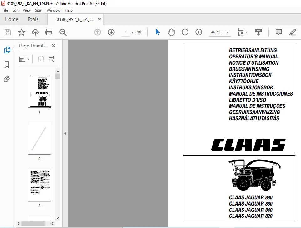
The self-propelled forage harvesters CLAAS JAGUAR 880, CLAAS JAGUAR 860, CLAAS JAGUAR 840 and CLAAS JAGUAR 820 head the wide CLAAS production range. This manual is intended to give the machine operator the necessary information on usage, adjustments and operation of the CLAAS forage harvesters. Provided all instructions are followed with regards to maintenance and care of your CLAAS forage harvester, you can count on many years of reliable service. Please have your authorized CLAAS dealer carry out the recommended regular inspections. The neglecting of regular maintenance and proper machine operation lead to reduced performance and loss of time. If proper operation and careful maintenance is ensured, your forage harvester, which incorporates latest harvesting technology, will render you excellent service.
Important notice
- The instructions contained in this manual should be carefully read and observed by all persons involved with the operation, maintenance and inspection of this machine in order to prevent accidents. Especially the sections »Safety Rules« and »Prior to Operation« should be read carefully.
- The use of spare parts, accessories and ancillary equipment, which are not original CLAAS products and/or have not specifically been tested and approved by CLAAS, can change the specified design characteristics of the CLAAS harvester or can detract from its functional performance, with a possible adverse effect on the active and/or passive operational safety and on its occupational safety standards (accident prevention).
- CLAAS will not be held liable for any damage or personal injury caused through the use of other than original or CLAAS approved parts, accessories and ancillary equipment. Machines with metal detection: Whilst total protection is not afforded, this machine will detect a high percentage of ferrous metal objects when they pass between the front feed rollers.
- Technical data, dimensions and weights are given as an indication only. CLAAS reserve the right to make changes subsequently as technical developments continue. Responsibility for errors or omissions not accepted. Front, rear, right and left refer to the direction of travel.
TABLE OF CONTENTS:
CLAAS JAGUAR 880 860 840 820 OPERATOR’S MANUAL – PDF DOWNLOAD
Important notice 4
Identification plate 8
Identification plate (up to machine-no ) 9
Identification plate (from machine-no ) 9
Identification plate – chopper unit 9
Engine serial number 10
Rear wheel drive axle – Sige 10
Serial numbers of 8-row maize header 11
Serial numbers of 6-row / 4-row maize header 11
Pick-up serial numbers 11
Safety rules 12
Start-off mirror – right hand side of machine 15
Safety decals with pictorials 17
1 Specifications
CLAAS JAGUAR 880 / 860 1 1
CLAAS JAGUAR 840 1 9
CLAAS JAGUAR 820 1 16
Safety features 1 23
Sectional view of forage harvester 1 24
2 Prior to operation
Work to be carried out prior-to-initial operation 2 1
Daily checks 2 1
Weekly checks 2 1
Operator’s platform 2 3
Cab 2 5
Cab with ventilating system and heating 2 6
Cab with air conditioner 2 6
Putting the compressor-type air conditioner
system into operation 2 7
Demister system 2 7
Malfunction, cause or remedy 2 8
Clock 2 9
Switch console 2 10
Multi-function lever
(hydrostatic drive lever) 2 12
Steering column 2 12
Vehicle information unit 2 13
Function of vehicle information unit 2 15
Adjusting the steering column position 2 15
Driver’s seat adjustment 2 15
Pneumatic driver’s seat 2 15
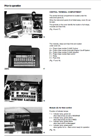
Central terminal compartment 2 16
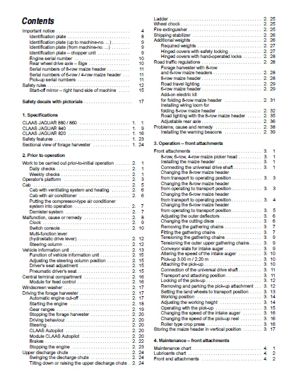
Module for feed control 2 16
Windscreen washer 2 17
Driving the forage harvester 2 17
Automatic engine cut-off 2 17
Starting the engine 2 18
Gear ranges 2 19
Stopping the forage harvester 2 20
Driving behaviour 2 20
Steering 2 20
CLAAS Autopilot 2 20
Module CLAAS Autopilot 2 20
Brakes 2 22
Stopping the engine 2 23
Upper discharge chute 2 24
Swinging the discharge chute 2 24
Tilting down or raising the upper discharge chute 2 24
Ladder 2 25
Wheel chock 2 25
Fire extinguisher 2 25
Shipping stabilizer 2 26
Additional weights 2 26
Required weights 2 27
Hinged covers with safety locking 2 27
Hinged covers with hand-operated locks 2 28
Road traffic regulations 2 28
Forage harvester with 8-row
and 6-row maize headers 2 28
8-row maize header 2 28
Road travel lighting 2 29
6-row maize header 2 29
Add-on electric kit
for folding 8-row maize header 2 31
Installing wiring loom for
folding 8-row maize header 2 32
Road lighting with the 8-row maize header 2 35
Adjustable rear axle 2 36
Problems, cause and remedy 2 38
Installing the warning beacons 2 39
3 Operation – front attachments
Front attachments 3 1
8-row, 6-row, 4-row maize picker head 3 1
Installing the maize header 3 1
Connecting the universal drive shaft 3 1
Changing the 8-row maize header
from transport to operating position 3 3
Changing the 8-row maize header
from operating to transport position 3 3
Changing the 6-row maize header
from transport to operating position 3 4
Changing the 6-row maize header
from operating to transport position 3 5
Adjusting the outer deflectors 3 6
Changing the cutting discs 3 6
Removing the gathering chains 3 7
Fitting the gathering chains 3 7
Tensioning the gathering chains 3 9
Tensioning the outer upper gathering chains 3 9
Conveyor slats for intake auger 3 9
Altering the speed of the intake auger 3 10
Pick-up 300 m / 220 m 3 10
Attaching the pick-up 3 10
Connection of the universal drive shaft 3 11
Transport and attaching position 3 11
Locking of the pick-up 3 12
Removing and parking the pick-up attachment 3 12
Setting the land wheels to transport position 3 13
Working position 3 14
Adjusting the working height 3 14
Operating with the pick-up 3 15
Changing the speed of the intake auger 3 16
Changing the speed of the pick-up reel 3 16
Roller type crop press 3 16
Storing the maize header in vertical position 3 17
4 Maintenance – front attachments
Maintenance chart 4 1
Lubricants chart 4 2
Front end attachments 4 2
6
Gearbox 4 2
Main gearbox 4 3
Spur gearbox 4 3
Chain drives 4 4
Main gearbox 4 4
Spur gearbox 4 5
Main gearbox 4 5
Spur gearbox 4 6
Angle drive gearbox 4 6
Drive chains 4 7
Tensioning the intake auger drive chain 4 7
Tension springs 4 7
Tensioning the intake auger springs 4 7
Setting the bearing arms for the cutting dics 4 8
Suspension springs 4 9
Adjusting the suspension springs 4 9
5 Lubrication chart – front attachments
6 Operation – basic machine
Cutting cylinder 6 1
Sharpening the cutting cylinder knives 6 1
Automatic knife sharpeners 6 1
Knife sharpener without remote controls 6 2
Knife sharpener with remote controls and
no electric shearbar adjustment installed 6 4
Finishing the sharpening process early 6 4
Resetting the electronic grinding cycle counter 6 6
Knife sharpener with remote controls
and electric shearbar adjustment 6 6
Adjusting the shearbar (machines
with electric shearbar adjustment) 6 7
Backing off the shearbar (machines
with electric shearbar adjustment) 6 7
Adjusting the shearbar (machines without
electronic shearbar adjustment) 6 10
Adjustment of the grinding stone 6 11
Resetting or replacing knives 6 12
Changing number of knives 6 14
Assembly direction of the knives 6 14
Micro-profile rasp bar system 6 15
Corn Cracker 6 16
Corn Cracker clearance gauge 6 16
Adjusting the Corn Cracker clearance 6 17
Basic setting of the Cracker Rollers 6 18
Removing the Corn Cracker 6 19
Locking the Corn Cracker in position 6 21
Attaching position for discharge
chute transition piece 6 21
Installing upper discharge chute
filler housing for the grass harvest 6 21
Lifting the Corn Cracker out of the machine 6 22
Concave plates 6 23
Adjusting the concave plate 6 24
Discharge 6 24
Discharge accelerator 6 24
Upper discharge chute 6 25
Swinging the upper discharge chute 6 25
Adjusting the length of cut 6 26
Gear ratios 6 27
Mechanical high-low speed range selection 6 27
Drive to front attachment 6 28
Contour System / preset height control 6 28
Adjusting the drop rate of the front attachment 6 28
Differences in the systems 6 29
Putting the Contour-System, Contour-Plus
and Preset Height into operation 6 30
Operating the unit with Contour System 6 31
Raising the front end attachment 6 32
Contour-Plus (only 8-row maize header) 6 32
Raising the front attachment 6 34
Activating Contour-plus 6 34
Preset height control 6 35
Adjusting the cutting height indicator 6 35
Adjusting the sender 6 35
Engaging the chopper unit drive 6 36
Turning on the chopper unit drive 6 36
Reversing the feed drives 6 37
Feed drives stop, detection system
has detected magnetizable metal 6 37
Removing the feed roller housing 6 38
Installing the feed roller housing 6 40
Guard under the cutting cylinder housing 6 41
Problems and remedy
(Auto sharpening) 6 43
Cutting cylinder knife sharpening 6 45
Problems cause or remedy 6 46
Sensor and potentiometer test 6 50
7 Maintenance – basic machine
Important maintenance instructions 7 1
Maintenance schedule 7 3
Lubricants chart 7 5
Hydraulic system 7 6
Checking the level of the oil 7 6
Changing hydraulic oil 7 6
Replacing hydraulic oil filter
at hydrostatic pump by a new one 7 7
Replacing hydraulic oil filter on
the low-pressure hydraulic circuit 7 7
Replacing the paper filter
element in the hydraulic oil tank 7 7
Cleaning screen filter 7 7
Filling instructions when
carrying out hydraulic oil change 7 8
Adjusting hydrostatic pump 7 9
Foot brakes / brake fluid 7 9
Transmissions 7 9
Ground drive change-speed transmission 7 9
Checking oil level 7 9
Oil change 7 9
Final drives gearboxes 7 10
Checking oil level 7 10
Oil change 7 10
Transfer gearbox 7 10
Checking oil level 7 10
Oil change 7 10
Gearbox for upper feed rollers 7 11
Checking oil level 7 11
Oil change 7 11
Drive casing for lower feed rollers 7 11
Speed-selection and reversing gearbox 7 11
Checking oil level 7 11
Oil change 7 12
Angle drive for top rollers 7 12
Checking oil level 7 12
Oil change 7 12
Angle drive for radiator fan 7 12
Checking oil level 7 12
7
Oil change 7 12
Rear wheel drive axle 7 12
Rear wheel drive 7 12
Sige rear wheel drive axle 7 13
Differential gearbox 7 13
Rear wheel final drives 7 13
Carraro rear wheel drive axle 7 14
Differential gearbox 7 14
Rear wheel final drives 7 14
Gear shift control adjustment 7 14
Discharge accelerator 7 15
Adjusting the accelerator impeller 7 16
Corn Cracker 7 18
Cleaning and preserving corn cracker 7 18
Greasing corn cracker 7 19
Checking corn cracker rollers 7 19
Corn cracker drive 7 20
Adjusting the scraper bar
on the plain feed roller 7 21
Fire extinguisher 7 21
Cab 7 21
Cleaning the filters 7 21
Compressor-type air conditioner 7 22
Tensioning the V-belt driving the compressor 7 22
Cleaning the condenser 7 22
Checking refrigerant level 7 22
Replacing the filter receiver drier 7 23
Required refrigerant quantity 7 23
Compressor-type air conditioner system
preventive maintenance
during prolonged shut down 7 24
Putting the compressor-type
air conditioner system into operation 7 25
Adjusting the tension of the
pre-compression and compression rollers 7 25
Adjusting the main drive spring-loaded cylinder 7 26
Slackening the tension of the power band belt 7 26
Upper discharge chute
breakaway safety device 7 27
Tolerance compensation of the
discharge chute breakaway safety device 7 27
Adjusting the feed drive 7 28
8 Central lubrication system
How the central lubrication system works 8 1
Central lubrication system
with 2-litre grease container 8 1
Central lubrication system
with 8-litre grease container
and mechanical pressure relief valves 8 2
Central lubrication system
with 8-litre grease container
and electronic pressure switch 8 2
Empty signal 8 3
Filling the grease container 8 3
Permissible types of grease 8 3
How long a fill will last 8 4
Putting the central lubrication
system into operation manually 8 4
2-litre grease container 8 4
8-litre grease container 8 5
Filling the system with a syringe 8 5
Greasing the machine manually 8 6
Operation without Corn Cracker 8 6
Operation with front attachment
without central lubrication 8 7
2-litre grease container and
8-litre grease container with
mechanical pressure relief valves 8 7
8-litre grease container with
electronic pressure switch 8 7
Replacing lubricating hoses 8 8
Assembling of lubricating hoses – machine side 8 8
Problem, cause or remedy 8 12
9 Lubrification chart – basic machine
10 Maintenance – engine
Important maintenance instructions 10 1
Maintenance schedule 10 2
Lubricants chart 10 3
Motors 10 4
Fuel feed system 10 5
Fuel tank 10 5
Manual fuel primer pump
with fuel sediment bowl 10 6
Fuel filter 10 6
Bleeding the fuel system 10 7
Water separator / fuel filter 10 7
Engine oil level check 10 8
Engine oil change 10 8
Oil filter 10 8
Filling in engine oil 10 9
Automatic engine cut-off 1010
V-belts 1011
Adjusting the spring-loaded
cylinder for the fan drive 1011
Tensioning the alternator V-belt 1012
Cooling system 1012
Coolant 1012
Water drain plugs on the engine block 1012
Radiator 1013
Filling the cooling system with coolant 1014
Overpressure 1014
Corrosion protection 1014
Warning sign 1014
Coolant temperature 1015
Radiator rotary screen 1015
Cleaning the cooling water radiator 1016
Cleaning rotor 1016
Dry-type air cleaner 1017
Warning device 1017
Air filter suction screen 1017
Cleaning dry-type air cleaner
with dust extractor unit 1017
Cleaning the air cleaner 1017
Dry-type air cleaner with
safety filter cartridge 1019
Batteries 1019
Battery isolating switch 1019
Battery and cable connections 1021
Colour code 1021
Engine problems, cause or remedy 1022
Engine winter storage 1024
IMAGES PREVIEW OF THE MANUAL:
CLAAS JAGUAR 880 860 840 820 OPERATOR’S MANUAL – PDF DOWNLOAD:
PLEASE NOTE:
- This is the SAME manual used by the dealers to troubleshoot any faults in your vehicle. This can be yours in 2 minutes after the payment is made.
- Contact us at [email protected] should you have any queries before your purchase or that you need any other service / repair / parts operators manual.
S.M