CLAAS JAGUAR 900 – 830 JAGUAR 900 – 830 Profistar JAGUAR 900 – 830 Speedstar Repair Manual
Original price was: $78.00.$34.95Current price is: $34.95.
CLAAS JAGUAR 900 – 830 JAGUAR 900 – 830 Profistar JAGUAR 900 – 830 Speedstar Repair Manual – PDF DOWNLOAD
Description
CLAAS JAGUAR 900 – 830 JAGUAR 900 – 830 Profistar JAGUAR 900 – 830 Speedstar Repair Manual – PDF DOWNLOAD
DESCRIPTION:
CLAAS JAGUAR 900 – 830 JAGUAR 900 – 830 Profistar JAGUAR 900 – 830 Speedstar Repair Manual – PDF DOWNLOAD
Introduction
- The enclosed CLAAS-REPAIR-MANUAL is intended to help maintain the continuous readiness for operation, and thus the high value, of the CLAAS forage harvester, by dedicated care and customer service technical monitoring.
- The experience of our customer service technicians and the experience gained in the factory is gathered together in this REPAIR-MANUAL.
- The sequence of illustrations shows the progression of each repair process, the text provides more information in the form of the notes required for the setting, the use of the CLAAS special tools etc.
- This includes the representation of the most important repairs so that individual and small tasks can be extracted and followed easily.
- The CLAAS-REPAIR-MANUAL is designed as a loose-leaf binder. It is added to continuously in the course of further technical developments of the machines and is therefore always an up-to-date reference document.
- For safety reasons, we would ask you always to compare the setting values and filling volumes with the currently-valid operating instructions of the individual machine
Introduction to the CLAAS Repair Manual
- The CLAAS-REPAIR-MANUAL is divided into main groups and sub-groups. With regard to the numbering at the foot of each page, the first figure indicates the main group, the figure behind the point is the sub-group and the figure after the second point is the page number.
- In each sub-group, the illustrations and pages are continuously numbered starting from 1. Differences between machine types are indicated by text or illustration notes. Fitting procedures which are valid for all machine types referred to in this manual, are kept neutral.
- In the case of additions, the sub-groups are added to or replaced. Any additions are filed under the relevant main group/sub-group and the index is replaced. The picture symbols serve to provide quick orientation in the case of recurring fitting procedures.
- Their significance is described at the beginning of this book. Extensive descriptions are given under the designation “GENERAL REPAIR NOTES” at the beginning of this book.
- Read and observe these important notes. They provide the basis for safe and long-term operation after repair work. The index for the relevant main group/sub-group provides easy, quick access to all fitting descriptions.
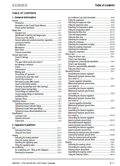
TABLE OF CONTENTS:
CLAAS JAGUAR 900 – 830 JAGUAR 900 – 830 Profistar JAGUAR 900 – 830 Speedstar Repair Manual – PDF DOWNLOAD
Table of contents 3
General information 11
General 13
Introduction 13
Introduction to the CLAAS Repair Manual 14
Picture symbol description 15
Safety rules 17
Important note 17
Identification of warning and danger signs 18
Correct use of the vehicle 18
General safety and accident prevention regulations 18
Leaving the machine 19
Air conditioner 19
Maintenance 19
Basic Rules 19
Pressure accumulator 19
General repair notes 21
Cause of damage 21
Parts 21
The repair will be quick and correct if the following is observed 21
Engine 21
Transmissions 21
Welding work 21
Three phase AC generator 21
Tensioning the steel roller chain 22
Conical ring connectors 22
Self-locking screws (MK-screws) 22
Liquid screw locking material 22
Clamping ring bearings (lock collar bearings) 23
Adapter sleeve bearing fitting 23
Ferrule fittings on hydraulic lines 23
Conical seating fittings on hydraulic/air conditioning lines 24
Hydraulic hoses 25
Tightening torques 27
Tightening torques screws 27
Tightening torques hydraulic fittings 29
Tightening torques brake pipe fittings 30
Tightening torques wheel bolts/wheel nuts 31
Specifications 33
Lubricants chart 33
Hydraulic pressures 35
Engine data 37
Operator’s platform 39
Cab 41
Removing front frame 41
Fitting the front frame 44
Heating 47
Removing the heating elements 47
Fitting the heating element 49
Removing the regulating valve 51
Fitting the regulating valve 53
Air conditioning 55
Air conditioning unit – filling up the refrigerant 55
Removing the evaporator 56
Air conditioner (cab side) dismantled 58
Fitting the evaporator 59
Removing the expansion valve 60
Fitting the expansion valve 61
Removing the temperature switch 62
Fitting the temperature switch 64
Removing the filter drier 65
Filter drier disassembled 66
Fitting the filter drier 66
Removing the condenser 66
Fitting the condenser 67
Removing the compressor coupling 68
Fitting the coupling compressor 71
Removing the compressor 73
Fitting the compressor 75
Driver’s seat 77
Fitting the driver’s seat 77
Driver’s seat dismantled (Isringhausen, pneumatically adjustable) 78
Driver’s seat dismantled (Grammer, pneumatically adjustable) 79
Fitting the driver’s seat 80
Operating Elements 81
Dismantling the traverse regulation (Mechanical-hydraulic traverse drive, up to serial no ) 81
Traverse regulation dismantled (Mechanical-hydraulic ground drive, up to serial no ) 82
Assembling the traverse regulation (Mechanical-hydraulic ground drive, up to serial no ) 83
Dismantling the traverse regulation (Mechanical-hydraulic traverse drive, from serial no ) 87
Traverse regulation dismantled (Mechanical-hydraulic ground drive, from serial no ) 89
Assembling the traverse regulation (Mechanical-hydraulic ground drive, from serial no ) 90
Dismantling the traverse regulation (electro-hydraulic ground drive) 95
Dismantled traverse regulation (electro-hydraulic ground drive) 97
Assembling the traverse regulation (electro-hydraulic ground drive) 99
Removing the traverse lever pull actuation (mechanical-hydraulic ground drive)104
Fitting the traverse lever pull actuation (mechanical-hydraulic ground drive)105
Steering109
Removing the steering column109
Dismantling the steering column113
Steering column dismantled:116
Assembling the steering column117
Fitting the Steering Column120
Removing the steering column (adjustable)125
Dismantling the steering column (adjustable)131
Steering column (adjustable) dismantled:133
Assembling the steering column (adjustable)134
Fitting the steering column (adjustable)136
Removing the steering unit (fixed steering column)140
Fitting the steering unit (fixed steering column)142
Removing the steering unit (adjustable steering column)145
Removing the steering unit (adjustable steering column)148
Checking/setting the steering unit151
Brakes153
Removing the parking brake actuation cable153
Fitting the parking brake actuation cable154
Removing the brake cylinder156
Fitting the brake cylinder156
Electrics157
Central electrics159
Removing the monitor (CIS)159
Fitting the monitor (CIS)160
Power supply163
Removing the regulator163
Fitting the regulator164
Removing the starter165
Fitting the starter166
Feed167
Feeder housing169
Removing the feeder housing169
Fitting the feeder housing170
Rollers173
Removing the feed roller and magnetic boxes173
Dismantling the lower feed roller and magnetic boxes174
Lower feed roller and magnetic boxes dismantled:179
Assembling the lower feed roller and magnetic boxes181
Fitting the lower feed roller and magnetic boxes187
Removing the upper compression roller189
Dismantling the upper compression roller191
Upper compression roller dismantled:194
Assembling the upper compression roller195
Fitting the upper compression roller200
Removing the upper rear compression roller201
Dismantling the upper rear compression roller203
Upper rear compression roller dismantled:206
Assembling the upper rear compression roller207
Assembling the upper rear compression roller211
Removing the lower smooth roller213
Dismantling the lower smooth roller214
Lower smooth roller dismantled:215
Assembling the lower smooth roller216
Fitting the lower smooth roller217
Tensioning the tension springs for the rollers218
Forage device221
Drum housing223
Removing the drum housing223
Fitting the drum housing226
Adjusting the drum disc229
Shear bar231
Removing the shear bar231
Fitting the shear bar232
Removing the shear bar support235
Shear bar support dismantled237
Fitting the shear bar support238
Removing the shear bar adjustment240
Shear bar adjustment dismantled243
Fitting the shear bar adjustment244
Basic setting of the shear bar250
Setting the shear bar (with mechanical shear bar adjustment)254
Setting the shear bar (with mechanical shear bar adjustment)255
Cutting cylinder257
Changing and setting the forage knife257
Removing the cutting cylinder260
Dismantling the cutting cylinder263
Cutting cylinder dismantled:265
Assembling the cutting cylinder267
Fitting the cutting cylinder269
Sharpening device273
Changing the sharpening stone273
Removing the sharpening device276
Dismantling the sharpening device277
Sharpening device dismantled:279
Assembling the sharpening unit280
Fitting the sharpening device282
Corn-Cracker285
Corn-Cracker287
Removing the Corn-Cracker287
Fitting the Corn-Cracker290
Removing the front roller292
Dismantling the front roller293
Front roller dismantled:295
Assembling the front roller296
Fitting the front roller298
Removing the rear roller300
Dismantling the rear roller302
Rear roller dismantled:304
Assembling the rear roller305
Fitting the rear roller308
Corn-Cracker gap adjustment311
Corn-Cracker gap adjustment removal311
Corn-Cracker gap adjustment dismantling312
Corn-Cracker gap adjustment (electric) dismantled:313
Corn-Cracker gap adjustment assembling314
Corn-Cracker gap adjustment fitting315
Transition piece319
Removing the guide plate319
Transition piece and guide plate dismantled320
Fitting the guide plate321
Discharge323
Blower325
Removing the blower bearing left325
Dismantling the blower bearing left326
Blower bearing left dismantled:327
Assembling the blower bearing left328
Fitting the blower bearing left329
Removing the blower bearing right332
Fitting the blower bearing right333
Removing the blower335
Fitting the blower337
Removing the blower housing341
Blower housing dismantled343
Fitting the blower housing344
Tower345
Removing the upper discharge chute345
Upper discharge chute dismantled:347
Fitting the upper discharge chute348
Rotary ring removal349
Gear ring dismantled351
Fitting the gear ring352
Removing the tower356
Tower dismantled358
Fitting the tower359
0298_826_1_RHB_EN_300_Teil2pdf 0
Table of contents 3
General information 11
General 13
Introduction 13
Introduction to the CLAAS Repair Manual 14
Picture symbol description 15
Safety rules 17
Important note 17
Identification of warning and danger signs 18
Correct use of the vehicle 18
General safety and accident prevention regulations 18
Leaving the machine 19
Air conditioner 19
Maintenance 19
Basic Rules 19
Pressure accumulator 19
General repair notes 21
Cause of damage 21
Parts 21
The repair will be quick and correct if the following is observed 21
Engine 21
Transmissions 21
Welding work 21
Three phase AC generator 21
Tensioning the steel roller chain 22
Conical ring connectors 22
Self-locking screws (MK-screws) 22
Liquid screw locking material 22
Clamping ring bearings (lock collar bearings) 23
Adapter sleeve bearing fitting 23
Ferrule fittings on hydraulic lines 23
Conical seating fittings on hydraulic/air conditioning lines 24
Hydraulic hoses 25
Tightening torques 27
Tightening torques screws 27
Tightening torques hydraulic fittings 29
Tightening torques brake pipe fittings 30
Tightening torques wheel bolts/wheel nuts 31
Specifications 33
Lubricants chart 33
Hydraulic pressures 35
Engine data 37
Operator’s platform 39
Cab 41
Removing front frame 41
Fitting the front frame 44
Heating 47
Removing the heating elements 47
Fitting the heating element 49
Removing the regulating valve 51
Fitting the regulating valve 53
Air conditioning 55
Air conditioning unit – filling up the refrigerant 55
Removing the evaporator 56
Air conditioner (cab side) dismantled 58
Fitting the evaporator 59
Removing the expansion valve 60
Fitting the expansion valve 61
Removing the temperature switch 62
Fitting the temperature switch 64
Removing the filter drier 65
Filter drier disassembled 66
Fitting the filter drier 66
Removing the condenser 66
Fitting the condenser 67
Removing the compressor coupling 68
Fitting the coupling compressor 71
Removing the compressor 73
Fitting the compressor 75
Driver’s seat 77
Fitting the driver’s seat 77
Driver’s seat dismantled (Isringhausen, pneumatically adjustable) 78
Driver’s seat dismantled (Grammer, pneumatically adjustable) 79
Fitting the driver’s seat 80
Operating Elements 81
Dismantling the traverse regulation (Mechanical-hydraulic traverse drive, up to serial no ) 81
Traverse regulation dismantled (Mechanical-hydraulic ground drive, up to serial no ) 82
Assembling the traverse regulation (Mechanical-hydraulic ground drive, up to serial no ) 83
Dismantling the traverse regulation (Mechanical-hydraulic traverse drive, from serial no ) 87
Traverse regulation dismantled (Mechanical-hydraulic ground drive, from serial no ) 89
Assembling the traverse regulation (Mechanical-hydraulic ground drive, from serial no ) 90
Dismantling the traverse regulation (electro-hydraulic ground drive) 95
Dismantled traverse regulation (electro-hydraulic ground drive) 97
Assembling the traverse regulation (electro-hydraulic ground drive) 99
Removing the traverse lever pull actuation (mechanical-hydraulic ground drive)104
Fitting the traverse lever pull actuation (mechanical-hydraulic ground drive)105
Steering109
Removing the steering column109
Dismantling the steering column113
Steering column dismantled:116
Assembling the steering column117
Fitting the Steering Column120
Removing the steering column (adjustable)125
Dismantling the steering column (adjustable)131
Steering column (adjustable) dismantled:133
Assembling the steering column (adjustable)134
Fitting the steering column (adjustable)136
Removing the steering unit (fixed steering column)140
Fitting the steering unit (fixed steering column)142
Removing the steering unit (adjustable steering column)145
Removing the steering unit (adjustable steering column)148
Checking/setting the steering unit151
Brakes153
Removing the parking brake actuation cable153
Fitting the parking brake actuation cable154
Removing the brake cylinder156
Fitting the brake cylinder156
Electrics157
Central electrics159
Removing the monitor (CIS)159
Fitting the monitor (CIS)160
Power supply163
Removing the regulator163
Fitting the regulator164
Removing the starter165
Fitting the starter166
Feed167
Feeder housing169
Removing the feeder housing169
Fitting the feeder housing170
Rollers173
Removing the feed roller and magnetic boxes173
Dismantling the lower feed roller and magnetic boxes174
Lower feed roller and magnetic boxes dismantled:179
Assembling the lower feed roller and magnetic boxes181
Fitting the lower feed roller and magnetic boxes187
Removing the upper compression roller189
Dismantling the upper compression roller191
Upper compression roller dismantled:194
Assembling the upper compression roller195
Fitting the upper compression roller200
Removing the upper rear compression roller201
Dismantling the upper rear compression roller203
Upper rear compression roller dismantled:206
Assembling the upper rear compression roller207
Assembling the upper rear compression roller211
Removing the lower smooth roller213
Dismantling the lower smooth roller214
Lower smooth roller dismantled:215
Assembling the lower smooth roller216
Fitting the lower smooth roller217
Tensioning the tension springs for the rollers218
Forage device221
Drum housing223
Removing the drum housing223
Fitting the drum housing226
Adjusting the drum disc229
Shear bar231
Removing the shear bar231
Fitting the shear bar232
Removing the shear bar support235
Shear bar support dismantled237
Fitting the shear bar support238
Removing the shear bar adjustment240
Shear bar adjustment dismantled243
Fitting the shear bar adjustment244
Basic setting of the shear bar250
Setting the shear bar (with mechanical shear bar adjustment)254
Setting the shear bar (with mechanical shear bar adjustment)255
Cutting cylinder257
Changing and setting the forage knife257
Removing the cutting cylinder260
Dismantling the cutting cylinder263
Cutting cylinder dismantled:265
Assembling the cutting cylinder267
Fitting the cutting cylinder269
Sharpening device273
Changing the sharpening stone273
Removing the sharpening device276
Dismantling the sharpening device277
Sharpening device dismantled:279
Assembling the sharpening unit280
Fitting the sharpening device282
Corn-Cracker285
Corn-Cracker287
Removing the Corn-Cracker287
Fitting the Corn-Cracker290
Removing the front roller292
Dismantling the front roller293
Front roller dismantled:295
Assembling the front roller296
Fitting the front roller298
Removing the rear roller300
Dismantling the rear roller302
Rear roller dismantled:304
Assembling the rear roller305
Fitting the rear roller308
Corn-Cracker gap adjustment311
Corn-Cracker gap adjustment removal311
Corn-Cracker gap adjustment dismantling312
Corn-Cracker gap adjustment (electric) dismantled:313
Corn-Cracker gap adjustment assembling314
Corn-Cracker gap adjustment fitting315
Transition piece319
Removing the guide plate319
Transition piece and guide plate dismantled320
Fitting the guide plate321
Discharge323
Blower325
Removing the blower bearing left325
Dismantling the blower bearing left326
Blower bearing left dismantled:327
Assembling the blower bearing left328
Fitting the blower bearing left329
Removing the blower bearing right332
Fitting the blower bearing right333
Removing the blower335
Fitting the blower337
Removing the blower housing341
Blower housing dismantled343
Fitting the blower housing344
Tower345
Removing the upper discharge chute345
Upper discharge chute dismantled:347
Fitting the upper discharge chute348
Rotary ring removal349
Gear ring dismantled351
Fitting the gear ring352
Removing the tower356
Tower dismantled358
Fitting the tower359
IMAGES PREVIEW OF THE MANUAL:
CLAAS JAGUAR 900 – 830 JAGUAR 900 – 830 PROFISTAR JAGUAR 900 – 830 SPEEDSTAR REPAIR MANUAL:
PLEASE NOTE:
- This is the SAME MANUAL used by the dealerships to diagnose your vehicle
- No waiting for couriers / posts as this is a PDF manual and you can download it within 2 minutes time once you make the payment.
Your payment is all safe and the delivery of the manual is INSTANT – You will be taken to the DOWNLOAD PAGE. - So have no hesitations whatsoever and write to us about any queries you may have : heydownloadss @gmail.com
S.M