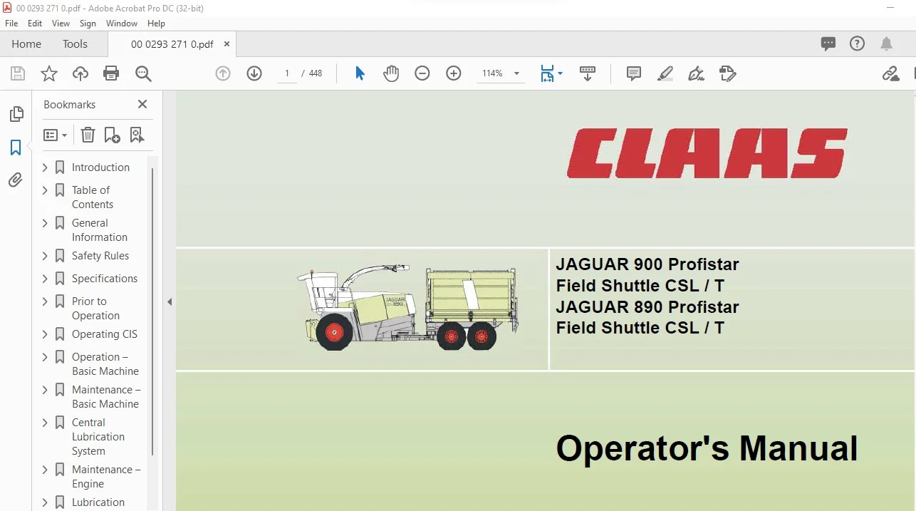
Claas JAGUAR 900 Profistar Field Shuttle CSL / T JAGUAR 890 Profistar Field Shuttle CSL / T Operator’s Manual – PDF DOWNLOAD
Original price was: $89.00.$27.95Current price is: $27.95.
Claas JAGUAR 900 Profistar Field Shuttle CSL / T JAGUAR 890 Profistar Field Shuttle CSL / T Operator’s Manual – PDF DOWNLOAD
Description
Claas JAGUAR 900 Profistar Field Shuttle CSL / T JAGUAR 890 Profistar Field Shuttle CSL / T Operator’s Manual – PDF DOWNLOAD
DESCRIPTION:
Claas JAGUAR 900 Profistar Field Shuttle CSL / T JAGUAR 890 Profistar Field Shuttle CSL / T Operator’s Manual – PDF DOWNLOAD
- INTRODUCTION
The following Operator’s Manual is for the CLAAS JAGUAR 900 – 890 Profistar Field Shuttles CSL / T and is the first source of information for the machine operator on the use, settings and the operation of the machine. In general, texts and - pictures apply to all machine models covered by this manual. Changes have been pointed out by the headings and text notes. Provided all instructions regarding maintenance and care of your machine are followed, you can count on many years of reliable service. Please have your authorized CLAAS dealer carry out the recommended regular inspections. The
- neglecting of regular maintenance and proper machine operation lead to reduced performance and loss of time. If proper operation and careful maintenance is ensured, your Field Shuttle CSL / T, which incorporates latest harvesting technology, will render you excellent service. Operator’s manuals for the front attachments are included as extras.
TABLE OF CONTENTS:
Claas JAGUAR 900 Profistar Field Shuttle CSL / T JAGUAR 890 Profistar Field Shuttle CSL / T Operator’s Manual – PDF DOWNLOAD
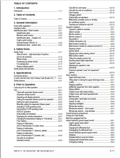
TABLE OF CONTENTS
1 Introduction
Introduction 111
2 Table of Contents
Table of Contents 211
3 General Information
Road traffic regulations 311
Important notice 321
Identification plate / Serial number 331
Identification plate 332
Machine serial number 332
Identification plate – chopper unit 332
Engine serial number
DaimlerChrysler OM 502 LA 333
Identification plate – tandem axle 333
4 Safety Rules
Safety Rules 411
Start-off mirror – right-hand side of machine
(not for all countries) 415
Wheel chocks 416
Positioning the wheel chocks 416
Fire extinguisher 417
Battery isolating switch 417
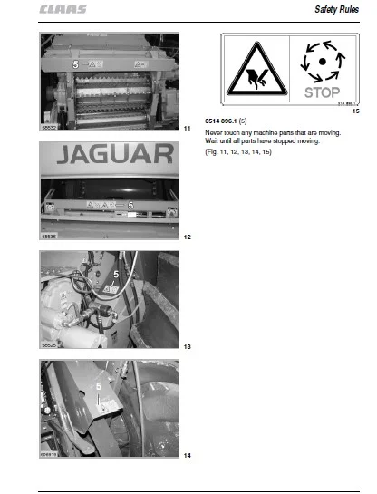
Safety decals with pictorials 421
5 Specifications
Conversion factors 511
CLAAS JAGUAR 900 / 890 Profistar Field Shuttle CSL / T 521
Safety features 531
6 Prior to Operation
Carry out prior to initial operation 611
Cab 621
Cabin with automatic climate control 621
Automatic climate control 622
Operating and display elements 622
Putting the automatic climate control into operation 623
Setting the cabin temperature 624
Manually setting the evaporator blower speed 624
Activating ECON operating mode 625
Deactivating ECON operating mode 625
REHEAT operation
(Dehumidify cab windows) 626
Displaying the outside temperature 627
Changing the temperature display to °Fahrenheit 627
Floor heating 627
Display of malfunction:
error in thermometer F0 (cabin, blue) 628
Display of malfunction:
error in thermometer F1 (exhaust, yellow) 628
Display of malfunction:
error in thermometer F2 (outside, red) 628
Cab with air conditioner
(standard version) 629
Cab with fan and heater 6210
Cab with fan and air conditioner 6210
Floor heating 6212
Defogger system
(Dehumidify cab windows) 6212
Malfunction, possible cause or remedy –
Air conditioner system 6213
Opening and closing the cab roof 6215
Operator’s platform 631
Operator’s platform overview 631
Switch console 633
Monitor section A 634
Monitor section B 635
Key portion C 636
Vehicle information unit 637
Multi-function handle (5) 638
Multi-function handle for container control (21) 639
Steering column 6310
Ignition switch 6310
Adjusting the entire steering column 6310
Multi-function switch 6311
Tilting the steering column top 6311
Steering wheel height adjustment 6311
Operator’s seat 6312
Adjusting the operator’s seat
(standard) 6312
Grammer operator’s seat “air suspension”
(option) 6313
Basic machine 641
Upper discharge chute 641
Tilting down or raising the upper discharge chute 641
Ladder 641
Shipping stabilizer 642
Additional equipment from other suppliers 642
Silage additive 642
Hinged covers with safety locking 643
Hinged covers with hand-operated locks 643
Machine tools 644
Driving lights / work lights and socket 644
Socket 12 volts 645
Adjusting headlights 646
Windscreen washer 647
Windscreen washer – front screen 647
Windscreen washer – side windows 647
Central terminal compartment 651
Driving the Field Shuttle
Machines equipped with the
electro-hydraulic ground speed control 661
Engine speed rotary switch 661
Differential lock 662
Engaging the differential lock 662
Disengaging the differential lock 662
Electro-hydraulic ground speed control 662
Stopping 662
Stopping without using the brakes 662
Stopping with limited brake action 663
Emergency braking 663
Table of Contents
212 BA JAGUAR 900 – 890 Field Shuttle CSL/T – 0293 2710
Table of Contents
Manoeuvering 663
Float position 664
Raise for road travel 664
Switching on the float position 664
Gear ranges 665
Starting the engine 666
Driving behaviour 666
Steering 667
Electro-hydraulic steering (CSL) 668
Control box 668
Control box (T) 669
Brakes 6610
Foot brake 6610
Parking brake 6611
Stopping the engine 6611
Towing the machine with the engine standing still 6612
Ensiling agent system 671
Electrical connections for the ensiling agent pump 671
Operating the ensiling agent pump 671
Activating the ensiling agent pump 671
Activating the purge cycle 671
Ensiling agent tank 672
Additive application nozzle 672
Adjustment of the fluid dosage 673
Selection of the nozzles 673
Compressed air brake system 681
Connecting the Field Shuttle T
compressed air hoses 681
Disconnecting the Field Shuttle T
compressed air hoses 681
Pressure indicator 681
Frost protection pump 682
Checking the safety valve 682
Antifreeze 682
Antifreeze – possible hazards – safety information 683
Electric box 691
Ground drive (CSL / T) 691
Container control unit (CSL) 691
7 Operating CIS
Introduction 711
Prior to operation 721
Displays and control elements 731
Overview – status displays A 731
Overview – monitor section B 732
Overview – key portion C 733
Main display 741
Monitoring engine rpm / engine loading 741
Monitoring the pressure of the lift cylinder
in connection with the ground pressure control 742
Monitoring the height of the
front attachment / Preset height setting 742
Display of functions / operating data 751
Display of operating data 751
Selecting a symbol or display 751
Showing and setting the time 752
Display of the Cracker roller gap 752
Display of the total accumulated working hours
(CIS with fieldwork computer) 753
Displaying / resetting the daily
accumulated working hours
(CIS with fieldwork computer) 753
Display of operating hours 754
Engine speed display 754
Setting the working speed 754
Displaying / resetting daily area recordings
(CIS with fieldwork computer) 756
Work rate display
(CIS with fieldwork computer) 756
Total area display
(CIS with fieldwork computer) 757
Display of next service due / time elapsed
(CIS with fieldwork computer) 757
Confirming that a service has been completed
(CIS with fieldwork computer) 758
“Learning” / storing machine data 761
Selecting a symbol / function 761
Function of keys 761
“Learning” the impulses per 100 m / setting the unit 762
Carrying out the calibration run 762
Direct input of the impulses / 100 m value 763
Setting the value 764
Programming the Cracker roller gap 765
Storing the working position
(CIS with fieldwork computer) 766
Setting the working width
(CIS with fieldwork computer) 767
Setting the division
(CIS with fieldwork computer) 768
Setting the partial width
(CIS with fieldwork computer) 7610
Operating sharpening and shear bar automatics 7611
Setting the sharpening sequence counter 7611
Sharpening memory function 7612
Adjusting the time interval until the next sharpening 7612
Monitoring the time until the next sharpening 7613
Switching on the automatic sharpening 7614
Automatic sharpening monitoring 7615
Resetting the sharpening sequences counter 7617
Shear bar gap adjustment 7618
Engaging the shear bar automatics 7619
Monitoring the shear bar automatics 7621
Resetting the life left of the knives 7622
Resetting the shear bar 7623
Checking the sharpening
and shear bar automatics sensors 7626
“Learning” the end stops of the Contour system 7628
Monitoring the potentiometer
front attachment height 7629
Setting the potentiometer front attachment height 7630
“Learning” the upper discharge chute end stops 7631
“Learning” the Field Shuttle control lever position 7632
Setting the driving strategy 7634
Problems and remedies 771
Types of alarm and fault code chart 771
Severe fault / continuous alarm 771
Less-severe fault / three alarm signals 772
0293 2710 – BA JAGUAR 900 – 890 Field Shuttle CSL/T 213
Table of Contents
Minor fault / one alarm signal 772
Fault code chart 773
8 Operation – Basic Machine
Chopping unit 811
Cutting cylinder 811
Sharpening the cutting cylinder knives 812
Automatic sharpening devices (option) 812
Sharpening knives with remote controls
and electric shear bar adjustment 813
Readjusting the shear bar
(Electric shear bar adjustment) 814
Resetting the electronic sharpening cycle counter 815
Resetting the shear bar
(Electric shear bar adjustment) 816
Sharpening the knives
(machine with standard sharpening unit) 8110
Readjusting the shear bar
(machines without electric shear bar adjustment) 8111
Resetting the shear bar
(machines without electric shear bar adjustment) 8112
Adjustment of the sharpening stone 8113
Turning the cutting cylinder 8115
Resetting or replacing knives 8115
Replacing the knives 8116
Replacing the shear bar 8117
Shear bar adjustment 8117
Changing number of knives 8117
Assembly direction of the knives 8118
Knife carrier protection 8118
Micro-profile rasp bar system 8119
Concave plates 8121
Adjusting the concave plates 8122
Discharge 8122
Discharge accelerator 8122
Upper discharge chute 8123
Adjusting the length of cut 8125
Gear ratios 8127
High-low speed range selection 8127
Fitting the bottom plate 8128
Guard under the cutting cylinder housing 8129
Corn Cracker 821
Corn Cracker gap gauge 821
Electrical gap adjustment 821
Mechanical gap adjustment 821
Programming the Corn Cracker gap
(Electric gap adjustment) 822
Basic adjustment of the Cracker rollers 824
Adjusting the roller gap manually
(Electrical Corn Cracker gap adjustment) 826
Removing the Corn Cracker 827
Locking the Corn Cracker in position 829
Attaching position for
discharge chute transition piece 829
Installing the discharge chute
transition piece for grass harvest 8210
Lifting the Corn Cracker out of the machine 8210
Fitting the Corn Cracker 8212
Attaching position for
discharge chute transition piece 8214
CLAAS Auto-Contour / Contour System /
Preset cutting height control 831
Adjusting the drop rate of the front attachment 831
Switch valve for front attachment 831
Differences in the systems 833
Putting the Auto-Contour System,
Contour System, Contour Plus and
preset cutting height control system into operation 834
Operating the Auto Contour System
(cutting height control with front attachment
lateral levelling) 836
Operating the Contour Plus System
(cutting height control) 838
Operating the Contour System
(ground pressure control) 8310
Preset height control 8312
Potentiometer for the cutting height 8312
Putting the chopper into operation 841
Engaging the chopper unit drive 842
Reversing the feed drives 843
Feed drives stop, detection system
has detected magnetizable metal 843
Lifting the roller crop guard 844
Feeder housing 851
Removing the feeder housing 851
Installing the feeder housing 853
Malfunction, possible cause or remedy – Auto sharpening 861
Cutting cylinder knife sharpening 861
Function of control lamp (17 – red) 861
Table of malfunctions – Auto sharpening 862
Sensor and potentiometer test 865
Steering programs (CSL) 871
Road travel steering program 871
Automatic operation of additional steering system 873
Pre-setting the steering angle of the
additional steering system (crab steer mode) 874
Calling up the saving after road travel 875
Deleting the saved value 875
Manual operation of additional steering system 875
Error messages 876
Setting an offset Boogie joint to
the straight ahead position when
the electro-hydraulic control unit fails 877
Container 881
Container operation (CSL) 881
Fold out discharge conveyor unit 881
Fold in discharge conveyor unit 881
Switching on the floor conveyor chain 881
Switching off the floor conveyor chain 881
Raising the container cover 882
Lowering the container cover 882
Raising the container 883
Lowering the container 883
Filling the container 884
Discharging the container 884
Manual upper discharge chute control 884
214 BA JAGUAR 900 – 890 Field Shuttle CSL/T – 0293 2710
Table of Contents
Automatic mode 884
Removing / installing the warning beacon 885
Switch console (Field Shuttle T) 891
Upper discharge chute control 891
Manual operation 891
Automatic operation 892
Calibration 894
Semi-trailer 8101
Hitching (Field Shuttle T) 8101
Unhitching (Field Shuttle T) 8102
9 Maintenance – Basic Machine
Important maintenance instructions 911
Important maintenance instructions
and safety rules 911
Maintenance schedule and lubricants charts 921
Maintenance schedule 921
Lubricants chart 924
Hydraulic system 931
Pressure accumulator 931
Checking the oil level 932
Changing hydraulic oil 932
Replacing hydraulic oil filter on hydrostatic pump 933
Cleaning/replacing the return filter 933
Cleaning/replacing the suction filter 934
Replacing the fresh air filter element 935
Filling instructions when
carrying out a hydraulic oil change 935
Check soiling indicator and replace
the hydraulic oil filter element if necessary 936
Foot brake, front axle, brake fluid 937
Multi-disc brake, tandem axle, hydraulic oil 937
Transmissions 941
Front manual gearbox 941
Checking the oil level 941
Oil change 941
Rear manual gearbox 942
Checking the oil level 942
Oil change 942
Final drive gearboxes 942
Checking the oil level 942
Oil change 942
Transfer gearbox 943
Checking the oil level 943
Oil change 943
Gearbox for upper feed rollers 943
Checking the oil level 943
Drive casing for lower feed rollers 943
Speed selection and reversing gearbox 944
Checking the oil level 944
Oil change 944
Spur gearbox for upper feed rollers 945
Checking the oil level 945
Oil change 945
Spur gear for floor conveyor 945
Checking the oil level 945
Oil change 945
Tandem axle differential 946
Checking the oil level 946
Oil change 946
Planetary gearbox 947
Oil change 947
Tandem box 947
Checking the oil level 947
Oil change 948
Cooling fan drive
(Engine) 948
Checking the oil level 948
Oil change 948
Maintenance – chopping unit 951
Discharge accelerator 951
Adjusting the accelerator impeller 952
Corn Cracker 953
Cleaning and preserving the Corn Cracker 953
Greasing the Corn Cracker
(Machines with central lubrication system) 954
Checking the Corn Cracker rollers 954
Corn Cracker drive 955
Wear plates in the discharge chute 956
Cleaning the discharge chute 957
Cleaning the inner chute of the machine 957
Adjusting the scraper bar on the plain feed roller 958
Adjusting the feed drive 958
Adjusting the tension of the
precompression and compression rollers 959
Front tension springs 959
Rear tension springs 959
Discharge chute breakaway safety device 9510
Tolerance compensation of the
discharge chute breakaway safety device 9510
Adjusting the main drive spring-loaded cylinder 961
Loosening the tension of the power band belt 961
Cab / Air conditioner 971
Cab 971
Cleaning the filters 971
Air conditioner 971
Cleaning the condenser 971
Checking the refrigerant level 972
Replacing the filter receiver drier 972
Required refrigerant quantity – Refrigerant R 134 a 972
Fire extinguisher 981
Left-hand drive belts 991
Removing the main drive belt (1) 991
Fitting and adjusting the main drive belt (1) 994
Right-hand drive belts 9101
Removing the cooling fan drive belt (10) 9101
Fitting and adjusting the cooling fan drive belt (10) 9102
Removing the Corn Cracker drive belt (11) 9103
Refitting and adjusting the
Corn Cracker drive belt (11) 9104
Removing the feed drive belt (12) 9105
Fitting and adjusting the feed drive belt (12) 9106
Compressed-air cleaning system 9111
Observe the following when withdrawing air 9112
Dewatering the compressed-air accumulator 9112
Compressed air brake system 9121
Dewatering the compressed-air accumulator 9121
0293 2710 – BA JAGUAR 900 – 890 Field Shuttle CSL/T 215
Table of Contents
Pressure controller 9122
Checking the safety valve 9122
Ensiling agent system 9131
Cleaning the nozzle 9131
Cleaning the filter 9131
Cleaning the ensiling agent system 9131
Wintering the ensiling agent pump system 9132
Container 9141
Check setting dimension of chain tensioners
for front and rear floor conveyor chains,
reduce chain length if necessary 9141
Field Shuttle winter storage 9151
10 Central Lubrication System
Operating the central lubrication system 1011
Central lubrication system (optional) 1011
Central lubrication system with 8-litre grease
container and electronic pressure switch 1012
Empty signal 1013
Filling the grease container 1013
Permissible types of grease 1013
How long a fill will last 1014
Grease container, 8 litres 1014
Putting the central lubrication system
into operation manually 1014
Filling the system with a syringe 1015
Filling with a filling pump 25/50 kg-container 1016
Filling via quick release connection 1016
Greasing the machine manually 1017
Operation without Corn Cracker 1017
Operation with front attachment
without central lubrication 1018
Replacing lubricating hoses 1021
Assembly of lubricating hoses – machine side 1021
Schema of central lubrication system 1024
Malfunction, possible cause or remedy –
Central lubrication system 1025
11 Maintenance – Engine
Important maintenance instructions 1111
Important maintenance instructions
and safety rules 1111
Maintenance schedules and lubricants charts 1121
Maintenance schedule 1121
Lubricants chart 1122
Engine overview 1131
Fuel system – Engine oil – V-belts 1141
Fuel feed system 1141
Fuel tank 1141
Manual fuel primer pump with fuel sediment bowl 1142
Fuel filter 1142
Fuel prefilter / water separator (standard version) 1142
Fuel prefilter / water separator (optional) 1143
Bleeding the fuel system 1144
Engine oil level check 1144
Engine oil change 1145
Oil filter 1146
Changing the bleeding filter 1146
Filling in engine oil 1146
V-belts 1147
Adjusting the spring-loaded cylinder
for the fan drive 1147
Cooling system 1151
Coolant 1151
Water drain plugs on the engine block 1151
Radiator 1152
Filling the cooling system with coolant 1152
Overpressure 1153
Frost protection / corrosion protection 1153
Warning sign 1153
Coolant temperature 1153
Radiator rotary screen 1154
Cleaning the water cooler, oil cooler and intercooler 1155
Cleaning rotor 1156
Air filter – Battery – Engine problems 1161
Dry-type air cleaner 1161
Warning device 1161
Cleaning the air filter suction screen 1161
Cleaning the dry-type air cleaner 1161
Safety filter cartridge 1164
Battery 1165
Alternator 1167
Engine malfunctions, possible cause or remedy 1168
Engine winter storage 1171
Engine preservation 1171
12 Lubrication Chart
Lubricants and lubrication instructions 1211
13 Index
Index 1311
IMAGES PREVIEW OF THE MANUAL:
CLAAS JAGUAR 900 PROFISTAR FIELD SHUTTLE CSL / T JAGUAR 890 PROFISTAR FIELD SHUTTLE CSL / T OPERATOR’S MANUAL – PDF DOWNLOAD:
PLEASE NOTE:
- This is the SAME manual used by the dealers to troubleshoot any faults in your vehicle. This can be yours in 2 minutes after the payment is made.
- Contact us at [email protected] should you have any queries before your purchase or that you need any other service / repair / parts operators manual.
S.M