Claas Jaguar 900 Profistar Jaguar 890 Profistar Operator’s Manual – PDF DOWNLOAD
Original price was: $86.95.$28.95Current price is: $28.95.
Claas Jaguar 900 Profistar Jaguar 890 Profistar Operator’s Manual – PDF DOWNLOAD
Description
Claas Jaguar 900 Profistar Jaguar 890 Profistar Operator’s Manual – PDF DOWNLOAD
DESCRIPTION:
Claas Jaguar 900 Profistar Jaguar 890 Profistar Operator’s Manual – PDF DOWNLOAD
INTRODUCTION:
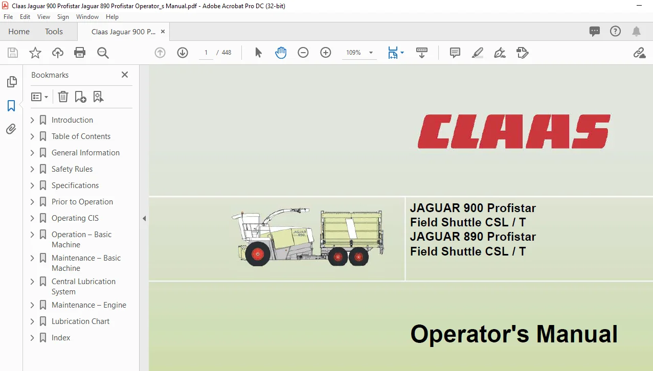
The following Operator’s Manual is for the CLAAS JAGUAR 900 – 890 Profistar Field Shuttles CSL / T and is the first source of information for the machine operator on the use, settings and the operation of the machine. In general, texts and pictures apply to all machine models covered by this manual.
- Changes have been pointed out by the headings and text notes. Provided all instructions regarding maintenance and care of your machine are followed, you can count on many years of reliable service. Please have your authorized CLAAS dealer carry out the recommended regular inspections.
- The neglecting of regular maintenance and proper machine operation lead to reduced performance and loss of time. If proper operation and careful maintenance is ensured, your Field Shuttle CSL / T, which incorporates latest harvesting technology, will render you excellent service. Operator’s manuals for the front attachments are included as extras.
TABLE OF CONTENTS:
Claas Jaguar 900 Profistar Jaguar 890 Profistar Operator’s Manual – PDF DOWNLOAD
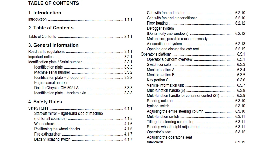
1 Introduction
Introduction 1 1 1
2 Table of Contents
Table of Contents 2 1 1
3 General Information
Road traffic regulations 3 1 1
Important notice 3 2 1
Identification plate / Serial number 3 3 1
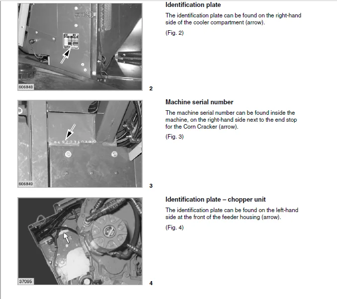
Identification plate 3 3 2
Machine serial number 3 3 2
Identification plate – chopper unit 3 3 2
Engine serial number
DaimlerChrysler OM 502 LA 3 3 3
Identification plate – tandem axle 3 3 3
4 Safety Rules
Safety Rules 4 1 1
Start-off mirror – right-hand side of machine
(not for all countries) 4 1 5
Wheel chocks 4 1 6
Positioning the wheel chocks 4 1 6
Fire extinguisher 4 1 7
Battery isolating switch 4 1 7
Safety decals with pictorials 4 2 1
5 Specifications
Conversion factors 5 1 1
CLAAS JAGUAR 900 / 890 Profistar Field Shuttle CSL / T 5 2 1
Safety features 5 3 1
6 Prior to Operation
Carry out prior to initial operation 6 1 1
Cab 6 2 1
Cabin with automatic climate control 6 2 1
Automatic climate control 6 2 2
Operating and display elements 6 2 2
Putting the automatic climate control into operation 6 2 3
Setting the cabin temperature 6 2 4
Manually setting the evaporator blower speed 6 2 4
Activating ECON operating mode 6 2 5
Deactivating ECON operating mode 6 2 5
REHEAT operation
(Dehumidify cab windows) 6 2 6
Displaying the outside temperature 6 2 7
Changing the temperature display to °Fahrenheit 6 2 7
Floor heating 6 2 7
Display of malfunction:
error in thermometer F0 (cabin, blue) 6 2 8
Display of malfunction:
error in thermometer F1 (exhaust, yellow) 6 2 8
Display of malfunction:
error in thermometer F2 (outside, red) 6 2 8
Cab with air conditioner
(standard version) 6 2 9
Cab with fan and heater 6 2 10
Cab with fan and air conditioner 6 2 10
Floor heating 6 2 12
Defogger system
(Dehumidify cab windows) 6 2 12
Malfunction, possible cause or remedy –
Air conditioner system 6 2 13
Opening and closing the cab roof 6 2 15
Operator’s platform 6 3 1
Operator’s platform overview 6 3 1
Switch console 6 3 3
Monitor section A 6 3 4
Monitor section B 6 3 5
Key portion C 6 3 6
Vehicle information unit 6 3 7
Multi-function handle (5) 6 3 8
Multi-function handle for container control (21) 6 3 9
Steering column 6 3 10
Ignition switch 6 3 10
Adjusting the entire steering column 6 3 10
Multi-function switch 6 3 11
Tilting the steering column top 6 3 11
Steering wheel height adjustment 6 3 11
Operator’s seat 6 3 12
Adjusting the operator’s seat
(standard) 6 3 12
Grammer operator’s seat “air suspension”
(option) 6 3 13
Basic machine 6 4 1
Upper discharge chute 6 4 1
Tilting down or raising the upper discharge chute 6 4 1
Ladder 6 4 1
Shipping stabilizer 6 4 2
Additional equipment from other suppliers 6 4 2
Silage additive 6 4 2
Hinged covers with safety locking 6 4 3
Hinged covers with hand-operated locks 6 4 3
Machine tools 6 4 4
Driving lights / work lights and socket 6 4 4
Socket 12 volts 6 4 5
Adjusting headlights 6 4 6
Windscreen washer 6 4 7
Windscreen washer – front screen 6 4 7
Windscreen washer – side windows 6 4 7
Central terminal compartment 6 5 1
Driving the Field Shuttle
Machines equipped with the
electro-hydraulic ground speed control 6 6 1
Engine speed rotary switch 6 6 1
Differential lock 6 6 2
Engaging the differential lock 6 6 2
Disengaging the differential lock 6 6 2
Electro-hydraulic ground speed control 6 6 2
Stopping 6 6 2
Stopping without using the brakes 6 6 2
Stopping with limited brake action 6 6 3
Emergency braking 6 6 3
Table of Contents
2 1 2 BA JAGUAR 900 – 890 Field Shuttle CSL/T – 0293 271 0
Table of Contents
Manoeuvering 6 6 3
Float position 6 6 4
Raise for road travel 6 6 4
Switching on the float position 6 6 4
Gear ranges 6 6 5
Starting the engine 6 6 6
Driving behaviour 6 6 6
Steering 6 6 7
Electro-hydraulic steering (CSL) 6 6 8
Control box 6 6 8
Control box (T) 6 6 9
Brakes 6 6 10
Foot brake 6 6 10
Parking brake 6 6 11
Stopping the engine 6 6 11
Towing the machine with the engine standing still 6 6 12
Ensiling agent system 6 7 1
Electrical connections for the ensiling agent pump 6 7 1
Operating the ensiling agent pump 6 7 1
Activating the ensiling agent pump 6 7 1
Activating the purge cycle 6 7 1
Ensiling agent tank 6 7 2
Additive application nozzle 6 7 2
Adjustment of the fluid dosage 6 7 3
Selection of the nozzles 6 7 3
Compressed air brake system 6 8 1
Connecting the Field Shuttle T
compressed air hoses 6 8 1
Disconnecting the Field Shuttle T
compressed air hoses 6 8 1
Pressure indicator 6 8 1
Frost protection pump 6 8 2
Checking the safety valve 6 8 2
Antifreeze 6 8 2
Antifreeze – possible hazards – safety information 6 8 3
Electric box 6 9 1
Ground drive (CSL / T) 6 9 1
Container control unit (CSL) 6 9 1
7 Operating CIS
Introduction 7 1 1
Prior to operation 7 2 1
Displays and control elements 7 3 1
Overview – status displays A 7 3 1
Overview – monitor section B 7 3 2
Overview – key portion C 7 3 3
Main display 7 4 1
Monitoring engine rpm / engine loading 7 4 1
Monitoring the pressure of the lift cylinder
in connection with the ground pressure control 7 4 2
Monitoring the height of the
front attachment / Preset height setting 7 4 2
Display of functions / operating data 7 5 1
Display of operating data 7 5 1
Selecting a symbol or display 7 5 1
Showing and setting the time 7 5 2
Display of the Cracker roller gap 7 5 2
Display of the total accumulated working hours
(CIS with fieldwork computer) 7 5 3
Displaying / resetting the daily
accumulated working hours
(CIS with fieldwork computer) 7 5 3
Display of operating hours 7 5 4
Engine speed display 7 5 4
Setting the working speed 7 5 4
Displaying / resetting daily area recordings
(CIS with fieldwork computer) 7 5 6
Work rate display
(CIS with fieldwork computer) 7 5 6
Total area display
(CIS with fieldwork computer) 7 5 7
Display of next service due / time elapsed
(CIS with fieldwork computer) 7 5 7
Confirming that a service has been completed
(CIS with fieldwork computer) 7 5 8
“Learning” / storing machine data 7 6 1
Selecting a symbol / function 7 6 1
Function of keys 7 6 1
“Learning” the impulses per 100 m / setting the unit 7 6 2
Carrying out the calibration run 7 6 2
Direct input of the impulses / 100 m value 7 6 3
Setting the value 7 6 4
Programming the Cracker roller gap 7 6 5
Storing the working position
(CIS with fieldwork computer) 7 6 6
Setting the working width
(CIS with fieldwork computer) 7 6 7
Setting the division
(CIS with fieldwork computer) 7 6 8
Setting the partial width
(CIS with fieldwork computer) 7 6 10
Operating sharpening and shear bar automatics 7 6 11
Setting the sharpening sequence counter 7 6 11
Sharpening memory function 7 6 12
Adjusting the time interval until the next sharpening 7 6 12
Monitoring the time until the next sharpening 7 6 13
Switching on the automatic sharpening 7 6 14
Automatic sharpening monitoring 7 6 15
Resetting the sharpening sequences counter 7 6 17
Shear bar gap adjustment 7 6 18
Engaging the shear bar automatics 7 6 19
Monitoring the shear bar automatics 7 6 21
Resetting the life left of the knives 7 6 22
Resetting the shear bar 7 6 23
Checking the sharpening
and shear bar automatics sensors 7 6 26
“Learning” the end stops of the Contour system 7 6 28
Monitoring the potentiometer
front attachment height 7 6 29
Setting the potentiometer front attachment height 7 6 30
“Learning” the upper discharge chute end stops 7 6 31
“Learning” the Field Shuttle control lever position 7 6 32
Setting the driving strategy 7 6 34
Problems and remedies 7 7 1
Types of alarm and fault code chart 7 7 1
Severe fault / continuous alarm 7 7 1
Less-severe fault / three alarm signals 7 7 2
0293 271 0 – BA JAGUAR 900 – 890 Field Shuttle CSL/T 2 1 3
Table of Contents
Minor fault / one alarm signal 7 7 2
Fault code chart 7 7 3
8 Operation – Basic Machine
Chopping unit 8 1 1
Cutting cylinder 8 1 1
Sharpening the cutting cylinder knives 8 1 2
Automatic sharpening devices (option) 8 1 2
Sharpening knives with remote controls
and electric shear bar adjustment 8 1 3
Readjusting the shear bar
(Electric shear bar adjustment) 8 1 4
Resetting the electronic sharpening cycle counter 8 1 5
Resetting the shear bar
(Electric shear bar adjustment) 8 1 6
Sharpening the knives
(machine with standard sharpening unit) 8 1 10
Readjusting the shear bar
(machines without electric shear bar adjustment) 8 1 11
Resetting the shear bar
(machines without electric shear bar adjustment) 8 1 12
Adjustment of the sharpening stone 8 1 13
Turning the cutting cylinder 8 1 15
Resetting or replacing knives 8 1 15
Replacing the knives 8 1 16
Replacing the shear bar 8 1 17
Shear bar adjustment 8 1 17
Changing number of knives 8 1 17
Assembly direction of the knives 8 1 18
Knife carrier protection 8 1 18
Micro-profile rasp bar system 8 1 19
Concave plates 8 1 21
Adjusting the concave plates 8 1 22
Discharge 8 1 22
Discharge accelerator 8 1 22
Upper discharge chute 8 1 23
Adjusting the length of cut 8 1 25
Gear ratios 8 1 27
High-low speed range selection 8 1 27
Fitting the bottom plate 8 1 28
Guard under the cutting cylinder housing 8 1 29
Corn Cracker 8 2 1
Corn Cracker gap gauge 8 2 1
Electrical gap adjustment 8 2 1
Mechanical gap adjustment 8 2 1
Programming the Corn Cracker gap
(Electric gap adjustment) 8 2 2
Basic adjustment of the Cracker rollers 8 2 4
Adjusting the roller gap manually
(Electrical Corn Cracker gap adjustment) 8 2 6
Removing the Corn Cracker 8 2 7
Locking the Corn Cracker in position 8 2 9
Attaching position for
discharge chute transition piece 8 2 9
Installing the discharge chute
transition piece for grass harvest 8 2 10
Lifting the Corn Cracker out of the machine 8 2 10
Fitting the Corn Cracker 8 2 12
Attaching position for
discharge chute transition piece 8 2 14
CLAAS Auto-Contour / Contour System /
Preset cutting height control 8 3 1
Adjusting the drop rate of the front attachment 8 3 1
Switch valve for front attachment 8 3 1
Differences in the systems 8 3 3
Putting the Auto-Contour System,
Contour System, Contour Plus and
preset cutting height control system into operation 8 3 4
Operating the Auto Contour System
(cutting height control with front attachment
lateral levelling) 8 3 6
Operating the Contour Plus System
(cutting height control) 8 3 8
Operating the Contour System
(ground pressure control) 8 3 10
Preset height control 8 3 12
Potentiometer for the cutting height 8 3 12
Putting the chopper into operation 8 4 1
Engaging the chopper unit drive 8 4 2
Reversing the feed drives 8 4 3
Feed drives stop, detection system
has detected magnetizable metal 8 4 3
Lifting the roller crop guard 8 4 4
Feeder housing 8 5 1
Removing the feeder housing 8 5 1
Installing the feeder housing 8 5 3
Malfunction, possible cause or remedy – Auto sharpening 8 6 1
Cutting cylinder knife sharpening 8 6 1
Function of control lamp (17 – red) 8 6 1
Table of malfunctions – Auto sharpening 8 6 2
Sensor and potentiometer test 8 6 5
Steering programs (CSL) 8 7 1
Road travel steering program 8 7 1
Automatic operation of additional steering system 8 7 3
Pre-setting the steering angle of the
additional steering system (crab steer mode) 8 7 4
Calling up the saving after road travel 8 7 5
Deleting the saved value 8 7 5
Manual operation of additional steering system 8 7 5
Error messages 8 7 6
Setting an offset Boogie joint to
the straight ahead position when
the electro-hydraulic control unit fails 8 7 7
Container 8 8 1
Container operation (CSL) 8 8 1
Fold out discharge conveyor unit 8 8 1
Fold in discharge conveyor unit 8 8 1
Switching on the floor conveyor chain 8 8 1
Switching off the floor conveyor chain 8 8 1
Raising the container cover 8 8 2
Lowering the container cover 8 8 2
Raising the container 8 8 3
Lowering the container 8 8 3
Filling the container 8 8 4
Discharging the container 8 8 4
Manual upper discharge chute control 8 8 4
2 1 4 BA JAGUAR 900 – 890 Field Shuttle CSL/T – 0293 271 0
Table of Contents
Automatic mode 8 8 4
Removing / installing the warning beacon 8 8 5
Switch console (Field Shuttle T) 8 9 1
Upper discharge chute control 8 9 1
Manual operation 8 9 1
Automatic operation 8 9 2
Calibration 8 9 4
Semi-trailer 8 10 1
Hitching (Field Shuttle T) 8 10 1
Unhitching (Field Shuttle T) 8 10 2
9 Maintenance – Basic Machine
Important maintenance instructions 9 1 1
Important maintenance instructions
and safety rules 9 1 1
Maintenance schedule and lubricants charts 9 2 1
Maintenance schedule 9 2 1
Lubricants chart 9 2 4
Hydraulic system 9 3 1
Pressure accumulator 9 3 1
Checking the oil level 9 3 2
Changing hydraulic oil 9 3 2
Replacing hydraulic oil filter on hydrostatic pump 9 3 3
Cleaning/replacing the return filter 9 3 3
Cleaning/replacing the suction filter 9 3 4
Replacing the fresh air filter element 9 3 5
Filling instructions when
carrying out a hydraulic oil change 9 3 5
Check soiling indicator and replace
the hydraulic oil filter element if necessary 9 3 6
Foot brake, front axle, brake fluid 9 3 7
Multi-disc brake, tandem axle, hydraulic oil 9 3 7
Transmissions 9 4 1
Front manual gearbox 9 4 1
Checking the oil level 9 4 1
Oil change 9 4 1
Rear manual gearbox 9 4 2
Checking the oil level 9 4 2
Oil change 9 4 2
Final drive gearboxes 9 4 2
Checking the oil level 9 4 2
Oil change 9 4 2
Transfer gearbox 9 4 3
Checking the oil level 9 4 3
Oil change 9 4 3
Gearbox for upper feed rollers 9 4 3
Checking the oil level 9 4 3
Drive casing for lower feed rollers 9 4 3
Speed selection and reversing gearbox 9 4 4
Checking the oil level 9 4 4
Oil change 9 4 4
Spur gearbox for upper feed rollers 9 4 5
Checking the oil level 9 4 5
Oil change 9 4 5
Spur gear for floor conveyor 9 4 5
Checking the oil level 9 4 5
Oil change 9 4 5
Tandem axle differential 9 4 6
Checking the oil level 9 4 6
Oil change 9 4 6
Planetary gearbox 9 4 7
Oil change 9 4 7
Tandem box 9 4 7
Checking the oil level 9 4 7
Oil change 9 4 8
Cooling fan drive
(Engine) 9 4 8
Checking the oil level 9 4 8
Oil change 9 4 8
Maintenance – chopping unit 9 5 1
Discharge accelerator 9 5 1
Adjusting the accelerator impeller 9 5 2
Corn Cracker 9 5 3
Cleaning and preserving the Corn Cracker 9 5 3
Greasing the Corn Cracker
(Machines with central lubrication system) 9 5 4
Checking the Corn Cracker rollers 9 5 4
Corn Cracker drive 9 5 5
Wear plates in the discharge chute 9 5 6
Cleaning the discharge chute 9 5 7
Cleaning the inner chute of the machine 9 5 7
Adjusting the scraper bar on the plain feed roller 9 5 8
Adjusting the feed drive 9 5 8
Adjusting the tension of the
precompression and compression rollers 9 5 9
Front tension springs 9 5 9
Rear tension springs 9 5 9
Discharge chute breakaway safety device 9 5 10
Tolerance compensation of the
discharge chute breakaway safety device 9 5 10
Adjusting the main drive spring-loaded cylinder 9 6 1
Loosening the tension of the power band belt 9 6 1
Cab / Air conditioner 9 7 1
Cab 9 7 1
Cleaning the filters 9 7 1
Air conditioner 9 7 1
Cleaning the condenser 9 7 1
Checking the refrigerant level 9 7 2
Replacing the filter receiver drier 9 7 2
Required refrigerant quantity – Refrigerant R 134 a 9 7 2
Fire extinguisher 9 8 1
Left-hand drive belts 9 9 1
Removing the main drive belt (1) 9 9 1
Fitting and adjusting the main drive belt (1) 9 9 4
Right-hand drive belts 9 10 1
Removing the cooling fan drive belt (10) 9 10 1
Fitting and adjusting the cooling fan drive belt (10) 9 10 2
Removing the Corn Cracker drive belt (11) 9 10 3
Refitting and adjusting the
Corn Cracker drive belt (11) 9 10 4
Removing the feed drive belt (12) 9 10 5
Fitting and adjusting the feed drive belt (12) 9 10 6
Compressed-air cleaning system 9 11 1
Observe the following when withdrawing air 9 11 2
Dewatering the compressed-air accumulator 9 11 2
Compressed air brake system 9 12 1
Dewatering the compressed-air accumulator 9 12 1
0293 271 0 – BA JAGUAR 900 – 890 Field Shuttle CSL/T 2 1 5
Table of Contents
Pressure controller 9 12 2
Checking the safety valve 9 12 2
Ensiling agent system 9 13 1
Cleaning the nozzle 9 13 1
Cleaning the filter 9 13 1
Cleaning the ensiling agent system 9 13 1
Wintering the ensiling agent pump system 9 13 2
Container 9 14 1
Check setting dimension of chain tensioners
for front and rear floor conveyor chains,
reduce chain length if necessary 9 14 1
Field Shuttle winter storage 9 15 1
10 Central Lubrication System
Operating the central lubrication system 10 1 1
Central lubrication system (optional) 10 1 1
Central lubrication system with 8-litre grease
container and electronic pressure switch 10 1 2
Empty signal 10 1 3
Filling the grease container 10 1 3
Permissible types of grease 10 1 3
How long a fill will last 10 1 4
Grease container, 8 litres 10 1 4
Putting the central lubrication system
into operation manually 10 1 4
Filling the system with a syringe 10 1 5
Filling with a filling pump 25/50 kg-container 10 1 6
Filling via quick release connection 10 1 6
Greasing the machine manually 10 1 7
Operation without Corn Cracker 10 1 7
Operation with front attachment
without central lubrication 10 1 8
Replacing lubricating hoses 10 2 1
Assembly of lubricating hoses – machine side 10 2 1
Schema of central lubrication system 10 2 4
Malfunction, possible cause or remedy –
Central lubrication system 10 2 5
11 Maintenance – Engine
Important maintenance instructions 11 1 1
Important maintenance instructions
and safety rules 11 1 1
Maintenance schedules and lubricants charts 11 2 1
Maintenance schedule 11 2 1
Lubricants chart 11 2 2
Engine overview 11 3 1
Fuel system – Engine oil – V-belts 11 4 1
Fuel feed system 11 4 1
Fuel tank 11 4 1
Manual fuel primer pump with fuel sediment bowl 11 4 2
Fuel filter 11 4 2
Fuel prefilter / water separator (standard version) 11 4 2
Fuel prefilter / water separator (optional) 11 4 3
Bleeding the fuel system 11 4 4
Engine oil level check 11 4 4
Engine oil change 11 4 5
Oil filter 11 4 6
Changing the bleeding filter 11 4 6
Filling in engine oil 11 4 6
V-belts 11 4 7
Adjusting the spring-loaded cylinder
for the fan drive 11 4 7
Cooling system 11 5 1
Coolant 11 5 1
Water drain plugs on the engine block 11 5 1
Radiator 11 5 2
Filling the cooling system with coolant 11 5 2
Overpressure 11 5 3
Frost protection / corrosion protection 11 5 3
Warning sign 11 5 3
Coolant temperature 11 5 3
Radiator rotary screen 11 5 4
Cleaning the water cooler, oil cooler and intercooler 11 5 5
Cleaning rotor 11 5 6
Air filter – Battery – Engine problems 11 6 1
Dry-type air cleaner 11 6 1
Warning device 11 6 1
Cleaning the air filter suction screen 11 6 1
Cleaning the dry-type air cleaner 11 6 1
Safety filter cartridge 11 6 4
Battery 11 6 5
Alternator 11 6 7
Engine malfunctions, possible cause or remedy 11 6 8
Engine winter storage 11 7 1
Engine preservation 11 7 1
12 Lubrication Chart
Lubricants and lubrication instructions 12 1 1
13 Index
Index 13 1 1
IMAGES PREVIEW OF THE MANUAL:
CLAAS JAGUAR 900 PROFISTAR JAGUAR 890 PROFISTAR OPERATOR’S MANUAL – PDF DOWNLOAD:
PLEASE NOTE:
- This is the SAME MANUAL used by the dealerships to diagnose your vehicle
- No waiting for couriers / posts as this is a PDF manual and you can download it within 2 minutes time once you make the payment.
- Your payment is all safe and the delivery of the manual is INSTANT – You will be taken to the DOWNLOAD PAGE.
- So have no hesitations whatsoever and write to us about any queries you may have : heydownloadss @gmail.com
S.V