CLAAS JAGUAR Type 493 Technical & Hydraulic System Service Manual – PDF DOWNLOAD
Original price was: $89.00.$24.95Current price is: $24.95.
CLAAS JAGUAR Type 493 Technical & Hydraulic System Service Manual – PDF DOWNLOAD
Description
CLAAS JAGUAR Type 493 Technical & Hydraulic System Service Manual – PDF DOWNLOAD
DESCRIPTION:
CLAAS JAGUAR Type 493 Technical & Hydraulic System Service Manual – PDF DOWNLOAD
Description of function
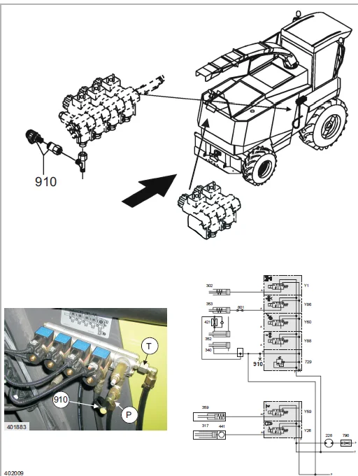
Oil pressure supply
The oil pressure required for performing the function is taken from the preloaded working hydraulics system.
Autopilot – steering to the left
The solenoid coil (Y9) is energised and opens the ball via the pilot spool. Oil flows from P1 to the lock-up valve unit via the ball. The non-return valve (port A) is opened by the oil flow against the spring force and oil flows to the steering cylinder. Before this, the pressure built up pushes the piston (K) towards port (B) and opens the non-return valve (port B). The oil coming from the cylinder return side flows via the open right non-return valve. The return flow lifts the pilot spool of the solenoid coil (Y10) and thus returns to the tank.
TABLE OF CONTENTS:
CLAAS JAGUAR Type 493 Technical & Hydraulic System Service Manual – PDF DOWNLOAD
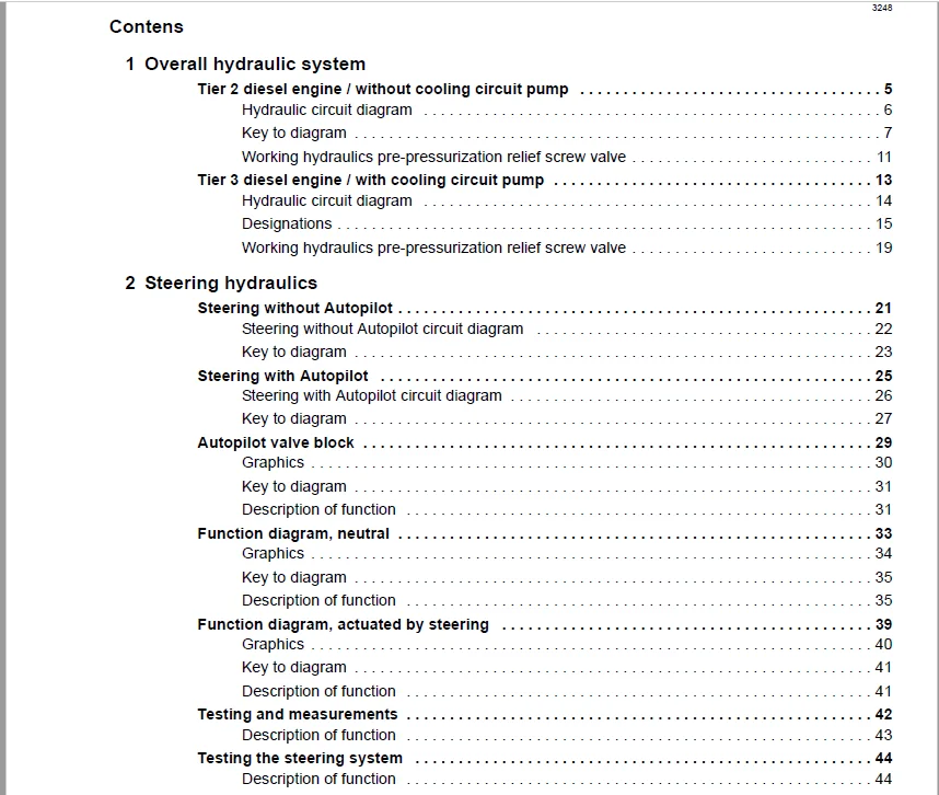
1 Overall hydraulic system 7
Tier 2 diesel engine / without cooling circuit pump 7
Hydraulic circuit diagram 8
Key to diagram 9
Working hydraulics pre-pressurization relief screw valve 13
Tier 3 diesel engine / with cooling circuit pump 15
Hydraulic circuit diagram 16
Designations 17
Working hydraulics pre-pressurization relief screw valve 21
2 Steering hydraulics 23
Steering without Autopilot 23
Steering without Autopilot circuit diagram 24
Key to diagram 25
Steering with Autopilot 27
Steering with Autopilot circuit diagram 28
Key to diagram 29
Autopilot valve block 31
Graphics 32
Key to diagram 33
Description of function 33
Function diagram, neutral 35
Graphics 36
Key to diagram 37
Description of function 37
Function diagram, actuated by steering 41
Graphics 42
Key to diagram 43
Description of function 43
Testing and measurements 44
Description of function 45
Testing the steering system 46
Description of function 46
3 Working hydraulics 47
Hydraulic circuit diagram 47
Working hydraulics circuit diagram 48
Key to diagram 49
Main valve: Circulation shut-off valve, front attachment raise/lower solenoid valve 53
Graphics 54
Key to diagram 55
Description of function 56
Upper discharge chute valve combination / discharge flap with pressure accumulator 59
Graphics 60
Key to diagram 61
Description of function 62
Hitch solenoid valve 63
Graphics 64
Key to diagram 65
Description of function 65
Sharpening, additional control unit 1, additional control unit 2 solenoid valve 67
Graphics 68
Key to diagram 69
Description of function 69
Corn cracker 71
Graphics 72
Key to diagram 73
Adjusting and venting 73
Upper discharge chute rotation drive motor 75
Graphics 76
Key to diagram 77
Front attachment load switch-over valve 79
Graphics 80
Key to diagram 81
Description of function 81
Pressure accumulator volume switch-over valve (Direct Disc option) 83
Graphics 84
Key to diagram 85
Description of function 85
Pitching dampening 86
Task 86
Operation 87
Sensors 88
Description of function 89
Testing and measuring 90
Graphics 90
Measuring pre-conditions 90
Set values 90
4 Low-pressure hydraulic system 91
Hydraulic circuit diagram 91
Low-pressure hydraulic system circuit diagram 92
Designations 93
All-wheel drive, servo gearshift, cover, reverse front attachment, front attachment clutch valve block 95
Fig 96
Designations 97
Description of function 98
Main drive valve block 99
Fig100
Designations101
Description of function101
Pressure relief valve103
Fig104
Designations105
Description of function105
Shifter rail locking hydraulic cylinder107
Fig108
Designations109
Description of function109
Venting110
Suction arm drive flow control valve111
Fig112
Designations113
Description of function113
Suction arm drive motor115
Fig116
Designations117
Line header119
Fig120
Designations121
Knife support valve cylinder123
Fig124
Designations125
Description of function125
Testing and measurements127
Fig128
Designations129
Measuring pre-condition129
5 Feeder hydraulics131
Hydraulic feeder drive, components131
Fig 132
Designations133
Main drive, decelerated135
Circuit diagram136
Fig 137
Designations137
Description of function138
Main drive ON139
Circuit diagram140
Fig 141
Designations141
Description of function142
Reversing143
Circuit diagram144
Fig 145
Designations145
Discription of function146
Feeder OFF147
Circuit diagram148
Fig 149
Designations149
Discription of function150
Feeding151
Circuit diagram152
Fig 153
Designations153
Description of function154
Quick stop155
Circuit diagram156
Fig 157
Designations157
Description of function158
6 Ground drive hydraulics159
Overall circuit diagram159
Ground drive hydraulics circuit diagram160
Designations161
Ground drive control164
Variable-displacement pump167
Fig169
Designations171
Variable-displacement motor173
Fig175
Designations177
Description of function177
High-pressure sensor (B97, B98)178
Fig178
Designations178
Description of function178
Testing and measurements179
Pressure testing with the high-pressure sensors (B97, B98), pressure display in the CIS terminal179
Fig179
High-pressure sensors measured value table (B97, B98)179
Functional check180
7 Compressed-air system181
Trailer brake system181
Circuit diagram182
Key to diagram182
Description of function183
Engine restrictor / Compressed-air coupling186
Circuit diagram186
Key to diagram186
Description of function187
8 Location of components189
Overview189
Individual components189
Overview203
Figures203
Index205
IMAGES PREVIEW OF THE MANUAL:
Need help? Contact: [email protected]
https://vimeo.com/676553348
CLAAS JAGUAR TYPE 493 TECHNICAL & HYDRAULIC SYSTEM SERVICE MANUAL – PDF DOWNLOAD:
PLEASE NOTE:
- This is not a physical manual but a digital manual – meaning no physical copy will be couriered to you. The manual can be yours in the next 2 mins as once you make the payment, you will be directed to the download page IMMEDIATELY.
- This is the same manual used by the dealers inorder to diagnose your vehicle of its faults.
- Require some other service manual or have any queries: please WRITE to us at [email protected]