CLAAS LEXION 405-460 Series Service Repair Manual PDF Download
Original price was: $78.00.$28.95Current price is: $28.95.
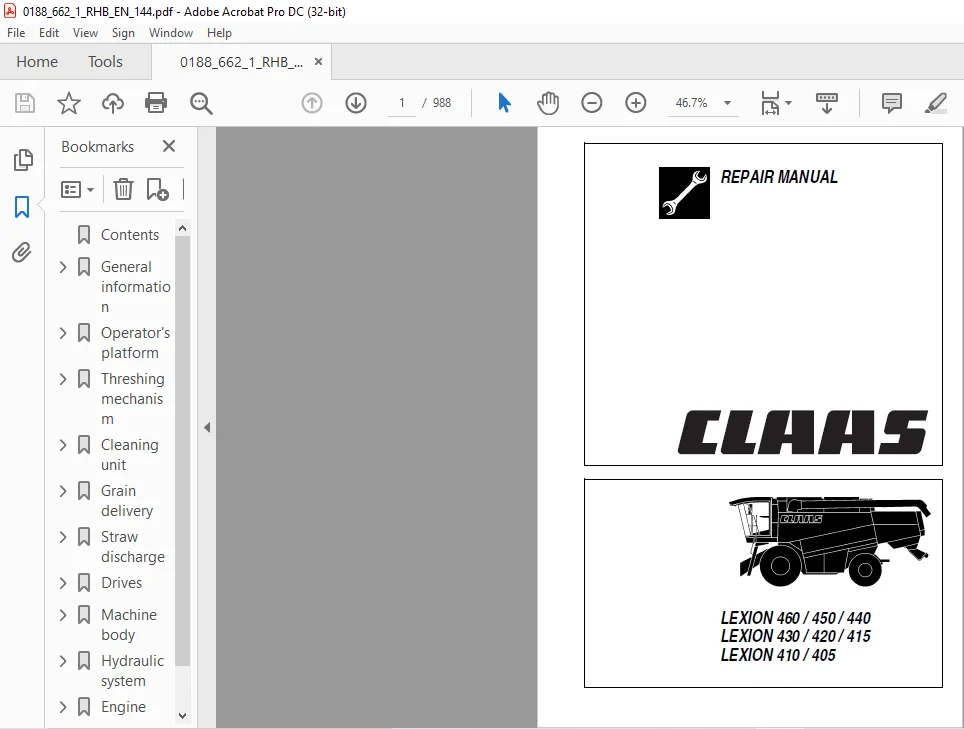
CLAAS LEXION 460 / 450 / 440 LEXION 430 / 420 / 415 LEXION 410 / 405 REPAIR MANUAL – PDF DOWNLOAD
Description
CLAAS LEXION 460 / 450 / 440 LEXION 430 / 420 / 415 LEXION 410 / 405 REPAIR MANUAL – PDF DOWNLOAD
DESCRIPTION:
CLAAS LEXION 460 / 450 / 440 LEXION 430 / 420 / 415 LEXION 410 / 405 REPAIR MANUAL – PDF DOWNLOAD
GENERAL
Introduction
- This CLAAS REPAIR MANUAL is to assist in preserving the permanent working order and therefore the high value of your CLAAS combine-harvester by careful maintenance and service. Experience gathered by both our service engineers and factory staff has been compiled in this REPAIR MANUAL.
- The figures explain the procedure of repairs and the text describes the different adjustments to be made, the use of CLAAS special tools etc. The illustrations included in support to the explanations show the sequence of major repairs so that minor repairs can easily be followed.
- The CLAAS REPAIR MANUAL is filled in a folder which allows to insert supplementary pages as issued following technical developments and to always have an updated manual at hand for reference.
- To be sure, always compare settings and filling capacities with specifications stated in the current Operator’s Manual which applies to the combineharvester.
Introduction to the CLAAS Repair Manual
- The CLAAS REPAIR MANUAL is divided into main groups and subgroups. The first figure at the bottom of each page refers to the main group whereas the second figure following the point indicates the subgroup; the figure behind the second point indicates the page number. In each subgroup, the figures and pages are numbered consecutively, starting at 1. Where differences between the machine types must be observed, this is indicated in headings.
- Where a service procedure applies to all machines covered by this book, the machine names are not specifically given. When supplements are to be added, the subgroups are supplemented or exchanged. Any possible supplements are filed in the respective main group / subgroup and the table of contents is updated and replaced.
- The symbols communicate brief messages when recurring service procedures are described. Their meaning is explained at the beginning of this manual.
- The section “GENERAL REPAIR INSTRUCTIONS” at the beginning of this manual contains useful practical hints. Read and follow these fundamental instructions. They are the basis for reliable service and durability of parts after repairs have been carried out.
- The description of a particular service procedure can easily be found by checking the table of contents of the appropriate main group / subgroup.
TABLE OF CONTENTS:
CLAAS LEXION 460 / 450 / 440 LEXION 430 / 420 / 415 LEXION 410 / 405 REPAIR MANUAL – PDF DOWNLOAD
Contents 0
General information 15
General 17
Introduction 17
Introduction to the CLAAS Repair Manual 18
Key to symbols 19
Safety Rules 21
Important notice 21
Identification of warning and danger signs 22
Correct use of the machine 22
General safety and accident prevention regulations 22
Leaving the machine 23
Compressor-type air conditioner 23
Maintenance 23
Basic rule 23
Pressure accumulator 23
General repair information 25
Reason of damage 25
Spare parts 25
Engine 25
Gearboxes 25
Alternator 25
Tensioning the steel roller chains 25
Taper ring fasteners 25
Self-locking bolts 25
Liquid locking compound 26
Correct installation of lock collar bearings 26
Correct installation of adapter sleeve bearings 26
Ferrule fittings on hydraulic lines 26
Progressive ring fittings on hydraulic lines 27
Taper fittings on hydraulic lines 27
Welding 27
Some advice for speedy and correct repair work: 28
Tightening torques 29
Bolts 29
Hydraulic fittings 30
Brake line screw joints 31
Wheel bolts 32
Safety features 32
Specifications 33
Lubricants chart 33
Hydraulic pressure values 34
Sectional view of machine 35
Drive diagram 39
Drive diagram, left-hand 39
Drive system diagram, right-hand side 40
Operator’s platform 41
Air conditioner 43
Important instructions regarding the compressor-type air conditioning system 43
Important instructions regarding the installation of parts in the compressor-type air conditioner 44
Air conditioning system – Topping up refrigerant 45
Checking / topping up the refrigerant oil level at the air conditioner compressor 46
Topping up refrigerant oil 47
Removing the condenser 47
Refitting the condenser 48
Removing the air conditioner compressor 49
Installing the air conditioner compressor 50
Removing the air conditioner compressor electro-magnetic clutch 50
Air conditioner compressor Sanden Sd 7h 15, disassembled 54
Installing the air conditioner compressor electro-magnetic clutch 55
Removing the air conditioner compressor cylinder head / cylinder head gasket 57
Installing the air conditioner compressor cylinder head / cylinder head gasket 58
Removing the air conditioner compressor shaft seal 59
Installing the air conditioner compressor shaft seal 61
Removing the expansion valve 62
Air conditioning system (cab side), disassembled 64
Installing the expansion valve 65
Removing the thermostat 65
Installing the thermostat 67
Removing the evaporator 68
Installing the evaporator 69
Removing the filter receiver drier 71
Filter receiver drier, disassembled 72
Installing the filter receiver drier 72
Steering 75
Scenes of failures on the Orbitrol steering unit 75
External leaks 75
Internal leaks 75
Removing the steering column 76
Disassembling the steering column 78
Steering column, disassembled: 81
Assembling the steering column 82
Installing the steering column 83
Removing the valve block from the Orbitrol 85
Installing the valve block on the Orbitrol 86
Removing the Orbitrol 88
Orbitrol, disassembled 88
Installing the Orbitrol 89
Parking brake 93
Removing the parking brake 93
Installing the parking brake 94
Foot brake 95
Removing the master brake cylinder 95
Master brake cylinder, disassembled 95
Assembling the master brake cylinder 95
Installing the master brake cylinder 96
Adjusting the master brake cylinder 96
Engine electric system 97
Alternator 97
Threshing mechanism 99
Feed rake conveyor101
Removing the feed rake conveyor101
Installing the feed rake conveyor103
Removing the intercepting piece104
Installing the intercepting piece104
Removing the feed rake conveyor suction blower105
Disassembling the feed rake conveyor suction blower105
Feed rake conveyor suction blower, disassembled:107
Assembling the feed rake conveyor suction blower108
Installing the feed rake conveyor suction blower109
Removing the top feed rake shaft109
Feed rake top shaft, disassembled LEXION 460 – 440115
Feed rake top shaft, disassembled LEXION 430 – 405116
Installing the feed rake top shaft117
Removing the bottom feed rake roller122
Bottom feed rake roller, disassembled LEXION 460 – 440124
Bottom feed rake roller, disassembled LEXION 430 – 405124
Assembling the bottom feed rake roller124
Installing the bottom feed rake roller125
Replacing the wooden ledges126
Removing the intermediate floor126
Installing the intermediate floor128
Replacing the runners129
Removing the intermediate drive shaft129
Intermediate drive shaft, disassembled134
Installing the intermediate drive shaft135
Removing the reverser drive136
Reverser drive, disassembled138
Installing the reverser drive139
Replacing the feeder chains139
Threshing concave143
Removing the stone trap143
Installing the stone trap143
Removing the preconcave144
Preconcave, disassembled147
Installing the preconcave148
Removing the main concave149
Main concave, disassembled151
Installing the main concave153
Basic concave setting157
Adjusting the concave potentiometer162
Learning the limit stops162
Learning the limit stops163
Accelerator165
Removing the bearing assembly and the shaft on the right-hand side165
Disassembling the right-hand bearing assembly167
Assembling the right-hand bearing167
Installing the right-hand bearing assembly and shaft169
Removing the bearing assembly on the left-hand side172
Disassembling the left-hand bearing assembly174
Assembling the left-hand bearing assembly175
Installing the left-hand bearing assembly176
Replacing the accelerator caps177
Removing the accelerator178
Accelerator, disassembled181
Installing the accelerator182
Threshing drum187
Removing the right-hand drum bearing assembly187
Disassembling the right-hand drum bearing189
Right-hand drum bearing, disassembled:190
Installing the right-hand drum bearing191
Removing the left-hand drum bearing assembly192
Disassembling the left-hand drum bearing194
Left-hand drum bearing assembly, disassembled:194
Installing the left-hand drum bearing assembly195
Removing the threshing drum196
Threshing drum, disassembled198
Renewing the beater bars199
Removing the threshing drum shaft200
Installing the threshing drum shaft202
Installing the threshing drum203
Impeller205
Removing the right-hand impeller bearing205
Installing the right-hand impeller bearing207
Removing the left-hand impeller bearing207
Installing the left-hand impeller bearing209
Removing the impeller210
Installing the impeller212
Removing the impeller shaft213
Installing the impeller shaft214
Removing the filler plates215
Installing the filler plates215
Cleaning unit217
Under-walker return floor219
Removing the under-walker return floor219
Rear rocker arm, disassembled:220
Installing the under-walker return floor220
Straw walker221
Removing the straw walker racks221
Installing the straw walker racks222
Removing the front straw walker crankshaft222
Installing the front straw walker crankshaft223
Removing the rear straw walker crankshaft223
Installing the rear straw walker crankshaft226
Disassembling the straw walker crankshafts227
Straw walker bearing, disassembled:230
Assembling the straw walker crankshaft231
Intensive separation system233
Replacing the agitator tines233
Removing the control shaft for the intensive separation system233
Removing the intensive separation system crankshaft234
Disassembling the intensive separation system crankshaft237
Assembling the intensive separation system crankshaft237
Installing the intensive separation system crankshaft238
Sieve pan239
Removing and installing the sieves239
Removing the upper sieves (from serial no )239
Removing the lower sieves (from serial no )240
Installing the sieves (from serial no )241
Tightening torques of axial mountings for the upper and lower sieves (from serial no )241
Sieves – Basic setting (electric sieve adjustment – from serial no )242
Removing the upper sieves (up to serial no )242
Removing the lower sieves (up to serial no )244
Installing the sieves (up to serial no )245
Tightening torques of axial mountings for the upper and lower sieves (up to serial no )246
Sieves – Basic setting (electric sieve adjustment – up to serial no )246
Removing the 3-D upper sieve frame247
3-D upper sieve frame, disassembled252
Installing the 3-D upper sieve frame253
Removing the sieve pan254
Sieve pan, disassembled257
Installing the sieve pan258
Checking and adjusting the alignment of preparation floor and sieve pan261
Preparation floor263
Removing the preparation floor263
Preparation floor, disassembled265
Installing the preparation floor266
3-D sieve pan control system267
Adjusting the 3-D sieve pan control system267
Adjusting pivot arm (A) with the “3-D gauge”268
Rocker arm drive269
Removing the intermediate drive shaft for the rocker arm drive269
Intermediate drive shaft for rocker arm drive, disassembled270
Installing the intermediate drive shaft for the rocker arm drive271
Cleaning fan273
Removing the bearings of the cleaning fan273
Cleaning fan bearing, disassembled276
Installing the cleaning fan bearing276
Removing the cleaning fan shaft277
Removing the centre cleaning fan bearing281
Centre cleaning fan bearing, disassembled281
Installing the cleaning fan shaft282
Removing the cleaning fan rotors283
Installing the cleaning fan rotors283
Removing the cleaning fan housing284
Installing the cleaning fan housing286
Grain delivery287
Returns elevator289
Removing the returns elevator chain289
Installing the returns elevator chain291
Removing the top returns auger291
Installing the top returns auger293
Removing the returns elevator294
Disassembling the returns elevator295
Assembling the returns elevator297
Installing the returns elevator297
Removing the returns elevator boot298
Installing the returns elevator boot299
Removing the lower returns auger299
Installing the lower returns auger301
Grain elevator303
Removing the clean grain elevator chain303
Installing the clean grain elevator chain304
Removing the clean grain elevator head305
Dismantling the clean grain elevator head306
Clean grain elevator head, disassembled:308
Assembling and installing the clean grain elevator head309
Removing the clean grain elevator shaft309
Installing the grain elevator shaft310
Removing the clean grain elevator boot311
Installing the clean grain elevator boot312
Removing the clean grain auger312
Installing the clean grain auger315
Removing the grain tank filler auger LEXION 460 – 420316
Removing the grain tank filler auger angle drive LEXION 460 – 420317
Disassembling the grain tank filler auger angle drive LEXION 460 – 420317
Grain tank filler auger, disassembled: LEXION 460 – 420319
Installing the grain tank filler auger LEXION 460 – 420320
Removing the grain tank filler auger LEXION 415 – 405322
Disassembling the grain tank filler auger angle drive LEXION 415 – 405323
Grain tank filler auger, disassembled: LEXION 415 – 405325
Installing the grain tank filler auger LEXION 415 – 405326
Grain tank unloading329
Removing the grain tank cross auger329
Grain tank cross augers, disassembled332
Installing the grain tank cross auger333
Removing the vertical grain tank unloading auger335
Installing the vertical grain tank unloading auger338
Removing the horizontal grain tank unloading auger339
Installing the horizontal grain tank unloading auger341
Removing the lower grain tank unloading angle drive (from serial no )341
Disassembling the lower grain tank unloading angle drive (from serial no )343
Lower grain tank unloading angle drive, disassembled: (from serial no …)346
Assembling the lower grain tank unloading angle drive (from serial no )347
Installing the lower grain tank unloading angle drive (from serial no )350
Removing the lower grain tank unloading angle drive (up to serial no )351
Disassembling the lower grain tank unloading angle drive (up to serial no )352
Lower grain tank unloading angle drive, disassembled: (up to serial no …)355
Assembling the lower grain tank unloading angle drive (up to serial no )356
Installing the lower grain tank unloading angle drive (up to serial no )359
Removing the upper grain tank unloading angle drive360
Disassembling the upper grain tank unloading angle drive361
Upper grain tank unloading angle drive, disassembled:362
Assembling the upper grain tank unloading angle drive363
Installing the upper grain tank unloading angle drive366
Removing the grain tank unloading tube367
Refitting the unloading auger tube368
Removing the grain tank unloading tube elbow368
Installing the grain tank unloading tube elbow369
Removing the vertical unloading auger tube369
Installing the vertical unloading auger tube370
Straw discharge371
Straw chopper373
Removing the right-hand straw chopper bearing373
Right-hand straw chopper bearing assembly, disassembled375
Installing the right-hand straw chopper bearing375
Removing the left-hand straw chopper bearing377
Left-hand straw chopper bearing assembly, disassembled378
Installing the left-hand straw chopper bearing378
Removing the cutting cylinder380
Cutting cylinder, disassembled381
Installing the cutting cylinder382
Replacing the free-swinging knives383
Replacing the straw chopper support runners386
Chaff spreader387
Disassembling the chaff spreader387
Assembling the chaff spreader389
Drives391
Drive belts393
General Information393
Drive system diagram, left-hand side394
Drive system diagram, right-hand side395
Left-hand drive belts397
Removing the cutterbar drive belt (1) (Cutterbar drive without variable-speed drive)397
Installing and adjusting the cutterbar drive belt (1) (Cutterbar drive without variable-speed drive)398
Removing the cutterbar drive belt (2) (Cutterbar drive with variable-speed drive)399
Installing and adjusting the cutterbar drive belt (2) (Cutterbar drive with variable-speed drive)400
Removing the cutterbar variable-speed drive belt (3)401
Installing and adjusting the cutterbar variable-speed drive belt (3)402
Removing the impeller drive belt (4)403
Installing and adjusting the impeller drive belt (4)404
Removing the cutterbar intermediate drive belt (5)405
Installing and adjusting the cutterbar intermediate drive belt (5)406
Removing the hydraulic pump drive belt for straw / chaff spreader (6)407
Installing and adjusting the hydraulic pump drive belt (6) for the straw / chaff spreader407
Removing the main intermediate drive belt (7)408
Installing and adjusting the main intermediate drive belt (7)410
Removing the grain tank unloading intermediate drive belt (8)412
Installing and adjusting the grain tank unloading intermediate drive belt (8)413
Removing the straw chopper intermediate drive belt (9)414
Installing and adjusting the straw chopper intermediate drive belt (9)415
Removing the straw chopper drive belt (10)416
Installing and adjusting the straw chopper drive belt (10)417
Removing the straw chopper drive belt (11)418
Installing and adjusting the straw chopper drive belt (11)419
Removing the straw chopper drive belt (12)420
Installing and adjusting the straw chopper drive belt (12)422
Removing the sieve pan / straw walker intermediate drive belt (13)423
Installing and adjusting the sieve pan / straw walker intermediate drive belt (13)424
Removing the sieve pan / straw walker intermediate drive belt (14)425
Installing and adjusting the sieve pan / straw walker intermediate drive belt (14)426
Removing the sieve pan drive belt (15)427
Installing and adjusting the sieve pan drive belt (15)429
Removing the straw walker drive belt (16)430
Installing and adjusting the straw walker drive belt (16)431
Removing the grain tank unloading drive chain (17)432
Installing and adjusting the grain tank unloading drive chain (17)433
Right-hand drive belts435
Removing the intensive separator system drive belts (18 and 19)435
Installing and adjusting the intensive separator system drive belts (18 and 19)436
Removing the fan intermediate drive belt (20)437
Installing and adjusting the fan intermediate drive belt (20)438
Removing the fan drive belt (21)439
Installing and adjusting the fan drive belt (21)439
Removing the threshing mechanism variable-speed drive belt (22)440
Installing and adjusting the threshing mechanism variable-speed drive belt (22)441
Removing the threshing drum drive belt (23)442
Installing and adjusting the threshing drum drive belt (23)443
Removing the accelerator drive belt (24)444
Installing and adjusting the accelerator drive belt (24)445
Removing the radiator chaff screen intermediate drive belt (25)446
Installing and adjusting the rotary chaff screen intermediate drive belt (25)447
Removing the radiator chaff screen drive belt (26)448
Installing and adjusting the rotary chaff screen drive belt (26)448
Removing the fan drive belt (27)449
Installing and adjusting the fan drive belt (27)450
Removing the suction blower drive belt (28)451
Installing and adjusting the suction blower drive belt (28)452
Removing the air conditioner compressor drive belt (29)453
Installing and adjusting the air conditioner compressor drive belt (29)454
Removing the compressed-air compressor drive belt (30)455
Installing and adjusting the compressed-air compressor drive belt (30)456
Removing the alternator drive belt (31)457
Installing and adjusting the alternator drive belt (31)458
Removing the feed rake conveyor suction blower drive belt (34)459
Installing and adjusting the feed rake conveyor suction blower drive belt (34)460
Removing the straw spreader drive belt (36)461
Installing and adjusting the straw spreader drive belt (36)462
Cutterbar drive467
Removing the front pulley of cutterbar drive (1)467
Installing the front pulley of cutterbar drive (1)468
Removing the deflection pulley of cutterbar drive (1)468
Deflection pulley of cutterbar drive (1), disassembled468
Installing the deflection pulley of cutterbar drive (1)469
Removing the slip clutch of cutterbar drive (1)469
Installing the slip clutch of cutterbar drive (1)470
Replacing the slip clutch linings of cutterbar drive (1)470
Slip clutch of cutterbar drive (1), disassembled471
Removing the jockey pulley of cutterbar drive (1)472
Jockey pulley of cutterbar drive (1), disassembled472
Removing the rear pulley of cutterbar drive (1) (up to serial no )472
Dismantling the rear pulley of cutterbar drive (1) (up to serial no )475
Rear pulley of cutterbar drive (1), disassembled: (up to serial no )477
Assembling the rear pulley of cutterbar drive (1) (up to serial no )478
Installing the rear pulley of cutterbar drive (1) (up to serial no )480
Removing the rear pulley of cutterbar drive (1) (from serial no )482
Dismantling the rear pulley of cutterbar drive (1) (from serial no )485
Rear pulley of cutterbar drive (1), disassembled: (from serial no )487
Assembling the rear pulley of cutterbar drive (1) (from serial no )488
Installing the rear pulley of cutterbar drive (1) (from serial no )489
Removing the cutterbar variable-speed pulley assembly (spring-loaded)491
Disassembling the cutterbar variable-speed pulley assembly (spring-loaded)492
Cutterbar variable-speed pulley assembly (spring-loaded), disassembled495
Assembling the cutterbar variable-speed pulley assembly (spring-loaded)496
Installing the cutterbar variable-speed pulley assembly (spring-loaded)500
Removing the cutterbar drive V-belt pulley when a cutterbar variable-speed drive is fitted502
Disassembling the cutterbar drive V-belt pulley when a cutterbar variable-speed drive is fitted502
Cutterbar drive V-belt pulley with a cutterbar variable-speed drive fitted, disassembled:504
Assembling the cutterbar drive V-belt pulley with a cutterbar variable-speed drive fitted505
Installing the cutterbar drive V-belt pulley with a cutterbar variable-speed drive fitted507
Removing and disassembling the cutterbar drive deflection pulley (2) with a cutterbar variable-sp507
Assembling and installing the cutterbar drive deflection pulley (2) with a cutterbar variable-spe508
Removing the cutterbar variable-speed pulley assembly (hydraulic)508
Disassembling the cutterbar variable-speed pulley assembly (hydraulic)511
Cutterbar variable-speed pulley assembly (hydraulic), disassembled:513
Assembling the cutterbar variable-speed pulley assembly (hydraulic)515
Installing the cutterbar variable-speed pulley assembly (hydraulic)516
Removing the cutterbar clutch517
Cutterbar clutch, disassembled524
Installing the cutterbar clutch525
Left-hand threshing mechanism drive531
Removing the threshing mechanism drive pulley assembly531
Threshing mechanism drive pulley assembly, disassembled537
Installing the threshing mechanism drive pulley assembly538
Right-hand threshing mechanism drive545
Removing the threshing drum variable-speed pulley assembly (hydraulic)545
Disassembling the threshing drum variable-speed pulley assembly (hydraulic)546
Threshing drum variable-speed pulley assembly (hydraulic), disassembled:548
Assembling the threshing drum variable-speed pulley assembly (hydraulic)550
Installing the threshing drum variable-speed pulley assembly (hydraulic)550
Removing the threshing drum variable-speed pulley assembly (spring-loaded)551
Disassembling the threshing drum variable-speed pulley assembly (spring-loaded)552
Threshing drum variable-speed pulley assembly (spring-loaded), disassembled:555
Assembling the threshing drum variable-speed pulley assembly (spring-loaded)556
Installing the threshing drum variable-speed pulley assembly (spring-loaded)560
Removing the threshing mechanism drive pulley562
Disassembling the threshing mechanism drive pulley562
Threshing mechanism drive pulley, disassembled:564
Assembling the threshing mechanism drive pulley565
Installing the threshing mechanism drive pulley567
Threshing drum reduction gearbox569
Removing the threshing drum reduction gearbox569
Disassembling the threshing drum reduction gearbox570
Threshing drum reduction gearbox, disassembled:574
Assembling the threshing drum reduction gearbox576
Installing the threshing drum reduction gearbox579
Threshing mechanism intermediate drive583
Removing the right-hand intermediate drive shaft bearing583
Installing the right-hand intermediate drive shaft bearing584
Removing the left-hand intermediate drive shaft bearing584
Installing the left-hand intermediate drive shaft bearing585
Removing the intermediate drive shaft586
Installing the intermediate drive shaft586
Grain tank unloading drive587
Removing the grain tank unloading drive pulley587
Installing the grain tank unloading drive pulley589
Chopper drive591
Removing the stage 1 chopper drive V-belt pulley591
Stage 1 chopper drive V-belt pulley, disassembled593
Assembling and installing the stage 1 chopper drive V-belt pulley594
Removing the stage 2 chopper drive V-belt pulley596
Stage 2 chopper drive V-belt pulley, disassembled598
Assembling and installing the stage 2 chopper drive V-belt pulley599
Removing the jockey pulley of straw chopper drive (10)601
Jockey pulley of straw chopper drive (10), disassembled601
Assembling and installing the jockey pulley of straw chopper drive (10)601
Removing the jockey pulley of straw chopper drive (11)602
Jockey pulley of straw chopper drive (11), disassembled602
Assembling and installing the jockey pulley of straw chopper drive (11)603
Removing the stage 3 chopper drive V-belt pulley603
Stage 3 chopper drive V-belt pulley, disassembled604
Assembling and installing the stage 3 chopper drive V-belt pulley604
Removing the stage 3 chopper drive jockey pulley605
Jockey pulley of stage 3 straw chopper drive, disassembled:605
Assembling and installing the stage 3 chopper drive jockey pulley606
Installing the straw chopper drive V-belt pulley607
Straw chopper drive V-belt pulley, disassembled607
Installing the straw chopper drive V-belt pulley608
Straw spreader drive609
Removing the straw spreader bearing housing609
Disassembling the straw spreader bearing housing610
Straw spreader bearing housing, disassembled:613
Assembling the straw spreader bearing housing615
Installing the straw spreader bearing housing617
Sieve pan drive621
Removing the sieve pan / straw walker drive V-belt pulley621
Sieve pan / straw walker drive V-belt pulley, disassembled622
Installing the sieve pan / straw walker drive V-belt pulley623
Removing the rear sieve pan drive deflection pulley624
Rear sieve pan drive deflection pulley, disassembled625
Assembling the rear sieve pan drive deflection pulley625
Installing the rear sieve pan drive deflection pulley625
Fan drive627
Removing the stage 1 fan drive V-belt pulley627
Stage 1 fan drive V-belt pulley, disassembled627
Installing the stage 1 fan drive V-belt pulley627
Fan adjustment (electric)628
Fan adjustment (electric) Version 1 (up to serial no )629
Fan adjustment (electric) Version 2 (from serial no …, up to serial no …)630
Fan adjustment (electric) Version 3 (from serial no )631
Removing the fan adjustment (electric) (Version 1)632
Disassembling the fan adjustment (electric) (Version 1)633
Fan adjustment (electric), disassembled: (Version 1)635
Assembling the fan adjustment (electric) (Version 1)636
Installing the fan adjustment (electric) (Version 1)638
Removing the fan adjustment (electric) (Version 1, version 3)640
Disassembling the fan adjustment (electric) (Version 1, version 3)641
Fan adjustment (electric), disassembled: (Version 1, version 3)643
Assembling the fan adjustment (electric) (Version 1, version 3)644
Installing the fan adjustment (electric) (Version 1, version 3)646
Removing the fan adjustment (electric) (Version 2)648
Disassembling the fan adjustment (electric) (Version 2)649
Fan adjustment (electric), disassembled: (Version 2)651
Assembling the fan adjustment (electric) (Version 2)652
Installing the fan adjustment (electric) (Version 2)655
Remove the electric fan variable-speed drive657
Electric fan variable-speed pulley assembly, disassembled658
Assembling and installing the electric fan variable-speed pulley assembly659
Removing the fan drive jockey pulley (20)662
Fan drive jockey pulley (20), disassembled662
Installing the fan drive jockey pulley (20)663
Removing the fan variable-speed pulley assembly (spring-loaded)663
Disassembling the fan drive variable-speed pulley assembly (spring-loaded)664
Fan variable-speed pulley assembly (spring-loaded), disassembled:666
Assembling the fan variable-speed pulley assembly (spring-loaded)667
Installing and adjusting the fan variable-speed pulley assembly (spring-loaded)668
Engine output669
Removing the engine output pulley669
Installing the engine output pulley669
Removing the transfer gearbox670
Disassembling the transfer gearbox675
Transfer gearbox, disassembled:679
Assembling the transfer gearbox680
Installing the transfer gearbox687
Rotary screen drive691
Removing the rotary screen drive691
Disassembling the rotary screen drive691
Rotary screen drive, disassembled:693
Assembling and installing the rotary screen drive694
Removing the fan drive695
Installing the fan drive695
Final drives697
Removing the final drive gearbox697
Disassembling the final drive gearbox697
Removing the wheel drive shaft697
Removing the intermediate shaft699
Removing the drive shaft701
Final drive gearbox, disassembled:702
Assembling the final drive gearbox704
Installing the drive shaft704
Installing the intermediate shaft705
Installing the wheel drive shaft707
Disassembling the planetary final drive gearbox711
Planetary final drive gearbox, disassembled:719
Assembling the planetary final drive gearbox720
Installing the final drive gearbox724
Manual gearbox727
Removing the manual gearbox727
Disassembling the manual gearbox729
Removing the shifter rails729
Removing the drive shaft731
Removing the main shaft732
Removing the differential734
Disassembling the differential735
Differential, disassembled:737
Assembling the differential737
Installing the differential739
Manual gearbox, disassembled741
Assembling the manual gearbox742
Installing the main shaft743
Installing the drive shaft744
Installing the shifter rails745
Installing the manual gearbox748
Servo gearshift751
Removing the shifter pistons751
Servo gearshift, disassembled:753
Installing the shifter pistons753
Bleeding the shifter piston754
Brake755
Parking brake – Replacing the brake linings755
Bleeding the brake system756
Disc brake – Changing the brake pads756
Removing a brake calliper757
Installing a brake calliper758
Steering axle759
Removing the wheel bearing759
Wheel bearing, disassembled762
Wheel bearing for rice option, disassembled763
Installing the wheel bearing764
Installing the wheel bearings for machines with the rice option766
Removing the stub axle767
Stub axle, disassembled769
Installing the stub axle770
Setting the track width771
Adjusting the steering axle end stops772
Removing the steering axle773
Steering axle bearing, disassembled774
Installing the steering axle775
Machine body777
Rotary screen779
Removing the rotary screen779
Disassembling the rotary screen779
Rotary screen, disassembled:781
Assembling and installing the rotary screen782
Trough and lateral panel, disassembled784
Adjusting the trough and the lateral panel (if suction blower with drive is fitted)785
Removing the fan drive786
Installing the fan drive786
Removing the rotary screen suction blower787
Disassembling the rotary screen suction blower787
Rotary screen suction blower, disassembled:789
Assembling and installing the rotary screen suction blower790
Drive axle791
Removing the drive axle791
Installing the drive axle794
Hydraulic system797
Oil cooler799
Removing the oil cooler799
Installing the oil cooler802
Maintenance803
Hydraulic system803
Checking the oil level803
Changing the hydraulic oil804
Filling instructions when changing the hydraulic oil805
Hydraulic pumps807
Removing the chaff spreader hydraulic pump807
Disassembling the chaff spreader hydraulic pump808
Chaff spreader hydraulic pump, disassembled:809
Assembling the chaff spreader hydraulic pump809
Installing the chaff spreader hydraulic pump810
Removing the ground drive hydraulic pump810
Installing the ground drive hydraulic pump813
Removing the hydraulic double pump814
Installing the hydraulic double pump814
Hydrostatic fixed displacement motors815
Removing the ground drive hydrostatic fixed displacement motor815
Installing the ground drive hydrostatic fixed displacement motor817
Removing the chaff spreader hydrostatic fixed displacement motor819
Installing the chaff spreader hydrostatic fixed displacement motor822
Removing the reverser drive hydrostatic fixed displacement motor823
Reverser drive hydrostatic fixed displacement motor, disassembled826
Installing the reverser drive hydrostatic fixed displacement motor827
Removing the straw spreader hydrostatic fixed displacement motors828
Installing the straw spreader hydrostatic fixed displacement motors830
Hydraulic cylinders – High-pressure hydraulic circuit831
Removing the cutterbar cross levelling hydraulic cylinders831
Disassembling the cutterbar cross levelling hydraulic cylinders831
Cutterbar cross levelling hydraulic cylinder, disassembled:833
Assembling the cutterbar cross levelling hydraulic cylinders834
Installing the cutterbar cross levelling hydraulic cylinders834
Bleeding the cutterbar cross levelling hydraulic cylinders836
Removing the cutterbar hydraulic cylinders837
Cutterbar hydraulic cylinders – Replacing the seals837
Disassembling the cutterbar hydraulic cylinders838
Cutterbar hydraulic cylinder, disassembled:840
Assembling the cutterbar hydraulic cylinder841
Installing the cutterbar hydraulic cylinders842
Adjusting the cutterbar hydraulic cylinders842
Removing the cutterbar variable-speed drive hydraulic cylinder843
Installing the cutterbar variable-speed drive hydraulic cylinder844
Disassembling the rotary coupling844
Rotary coupling, disassembled846
Assembling the rotary coupling847
Removing the concave adjustment hydraulic cylinder848
Disassembling the concave adjustment hydraulic cylinder849
Concave adjustment hydraulic cylinder, disassembled:851
Assembling the concave adjustment hydraulic cylinder852
Installing the concave adjustment hydraulic cylinder853
Removing the grain tank unloading tube swing hydraulic cylinder853
Disassembling the grain tank unloading tube swing hydraulic cylinder853
Grain tank unloading tube swing hydraulic cylinder, disassembled:855
Assembling the grain tank unloading tube swing hydraulic cylinder856
Installing the grain tank unloading tube swing hydraulic cylinder857
Removing the straw chopper drive hydraulic cylinder857
Disassembling the straw chopper drive hydraulic cylinder858
Straw chopper drive hydraulic cylinder, disassembled:859
Assembling the straw chopper drive hydraulic cylinder859
Installing the straw chopper drive hydraulic cylinder860
Removing the threshing drum variable-speed drive hydraulic cylinder860
Installing the threshing drum variable-speed drive hydraulic cylinder861
Removing the reverser drive hydraulic cylinder862
Disassembling the reverser drive hydraulic cylinder862
Reverser drive hydraulic cylinder, disassembled:863
Assembling the reverser drive hydraulic cylinder864
Installing the reverser drive hydraulic cylinder864
Hydraulic cylinders for low-pressure hydraulics867
Removing the threshing mechanism engagement hydraulic cylinder867
Disassembling the threshing mechanism engagement hydraulic cylinder868
Threshing mechanism engagement hydraulic cylinder, disassembled:868
Assembling the threshing mechanism engagement hydraulic cylinder869
Installing the threshing mechanism engagement hydraulic cylinder870
Removing the grain tank unloading engagement hydraulic cylinder870
Disassembling the grain tank unloading engagement hydraulic cylinder871
Grain tank unloading engagement hydraulic cylinder, disassembled:872
Assembling the grain tank unloading engagement hydraulic cylinder873
Installing the grain tank unloading engagement hydraulic cylinder874
Removing the engine speed control hydraulic cylinder (from serial no )875
Disassembling the engine speed control hydraulic cylinder (from serial no )875
Engine speed control hydraulic cylinder, disassembled: (from serial no )877
Assembling the engine speed control hydraulic cylinder (from serial no )878
Pre-setting the engine speed control hydraulic cylinder (from serial no )880
Installing the engine speed control hydraulic cylinder (from serial no )880
Setting the engine speed control hydraulic cylinder (from serial no )881
Changing the road travel engine speed (country variants 20 km/h and/or 25 km/h) by converting the882
Conversion of cylinder to another country variant (20 km/h and/or 25 km/h)882
Removing the engine speed control hydraulic cylinder (up to serial no )886
Disassembling the engine speed control hydraulic cylinder (up to serial no )886
Engine speed control hydraulic cylinder, disassembled: (up to serial no …)889
Assembling the engine speed control hydraulic cylinder (up to serial no )890
Pre-setting the engine speed control hydraulic cylinder (up to serial no )891
Installing the engine speed control hydraulic cylinder (up to serial no )891
Setting the engine speed control hydraulic cylinder (up to serial no )892
Removing the straw chopper hydraulic cylinder894
Disassembling the straw chopper hydraulic cylinder894
Straw chopper hydraulic cylinder, disassembled:896
Assembling the straw chopper hydraulic cylinder897
Installing the straw chopper hydraulic cylinder898
Removing the 3-D sieve pan hydraulic cylinder898
Disassembling the 3-D sieve pan hydraulic cylinder898
3-D sieve pan hydraulic cylinder, disassembled:900
Assembling the 3-D sieve pan hydraulic cylinder901
Installing the 3-D sieve pan hydraulic cylinder902
Removing the pendulum control unit of the 3-D sieve pan902
Disassembling the 3-D sieve pan pendulum control unit902
Pendulum control unit of 3-D sieve pan, disassembled:904
Assembling the pendulum control unit for 3-D sieve pan905
Installing the 3-D sieve pan pendulum control unit905
Removing the yield meter moisture sensor hydraulic cylinder906
Disassembling the yield meter moisture sensor hydraulic cylinder907
Yield meter moisture sensor hydraulic cylinder, disassembled:908
Assembling the yield meter moisture sensor hydraulic cylinder908
Installing the yield meter moisture sensor hydraulic cylinder909
Checking and adjusting the yield meter hydraulic cylinder909
Yield meter hydraulic cylinder, disassembled911
Hydraulic cylinder – Steering hydraulics913
Removing the steering cylinder913
Disassembling the steering cylinder913
Steering cylinder, disassembled:915
Assembling the steering cylinder916
Installing the steering cylinder917
Removing the Autopilot steering cylinder917
Disassembling the Autopilot steering cylinder918
Autopilot steering cylinder, disassembled:921
Assembling the Autopilot steering cylinder922
Installing the Autopilot steering cylinder923
Valve combinations925
Removing the feeder reversing 3/2-way valve925
Feeder reversing 3/2-way valve, disassembled925
Removing the cutterbar cross levelling 4/3-way valve926
Cutterbar cross levelling 4/3-way valve, disassembled927
Removing the concave adjustment pressure relief valve928
Concave adjustment pressure relief valve, disassembled928
Assembling the concave adjustment pressure relief valve928
Removing the cutterbar and threshing drum variable-speed drive 3/3-way valves928
Cutterbar and threshing drum variable- speed drive 3/3-way valve, disassembled930
Installing the cutterbar and threshing drum variable-speed drive 3/3-way valves931
Removing the threshing drum variable-speed drive 3/3-way valve931
Threshing drum variable-speed drive 3/3-way valve, disassembled932
Removing the concave, grain tank unloading tube and straw chopper 4/3-way valves933
Concave, grain tank unloading tube and straw chopper 4/3-way valve, disassembled934
Assembling the concave, grain tank unloading tube and straw chopper 4/3-way valves935
Installing the concave, grain tank unloading tube and straw chopper 4/3-way valves935
Removing the concave and grain tank unloading tube 4/3 way valves935
Concave and grain tank unloading tube 4/3-way valve, disassembled937
Assembling the concave and grain tank unloading tube 4/3-way valves938
Installing the concave and grain tank unloading tube 4/3-way valves938
Removing the main valve938
Main valve, disassembled940
Assembling the main valve941
Installing the main valve941
Removing the CLAAS Autopilot solenoid valve942
CLAAS Autopilot solenoid valve, disassembled943
Assembling the CLAAS Autopilot solenoid valve944
Installing the CLAAS Autopilot solenoid valve944
Removing the low-pressure solenoid valve block944
Low-pressure solenoid valve block, disassembled946
Assembling the low-pressure solenoid valve block947
Installing the low-pressure solenoid valve block947
Removing the chaff spreader flow divider948
Installing the chaff spreader flow divider949
Removing the low-pressure solenoid valve (yield meter)949
Yield meter 3/2-way solenoid valve, disassembled951
Installing the low-pressure solenoid valve (yield meter)951
Engine953
Cooling system955
Removing the intercooler955
Installing the intercooler957
Removing the radiator957
Installing the radiator960
Fuel system961
Removing the fuel tank961
Installing the fuel tank962
Engine963
Removing the engine963
Installing the engine969
Index973
Index975
Numerical975
A975
B976
C976
D976
E977
F977
G978
H978
I978
J980
K981
L981
M981
O981
P981
R981
S984
T984
U985
V985
W985
Y985
IMAGES PREVIEW OF THE MANUAL:
CLAAS LEXION 460 / 450 / 440 LEXION 430 / 420 / 415 LEXION 410 / 405 REPAIR MANUAL – PDF DOWNLOAD:
PLEASE NOTE:
- This is not a physical manual but a digital manual – meaning no physical copy will be couriered to you. The manual can be yours in the next 2 mins as once you make the payment, you will be directed to the download page IMMEDIATELY.
- This is the same manual used by the dealers inorder to diagnose your vehicle of its faults.
- Require some other service manual or have any queries: please WRITE to us at [email protected]
S.M