CLAAS LEXION 480 Repair Manual PDF Download
Original price was: $78.00.$31.95Current price is: $31.95.
CLAAS LEXION 480 REPAIR MANUAL – PDF DOWNLOAD
Description
CLAAS LEXION 480 REPAIR MANUAL – PDF DOWNLOAD
DESCRIPTION:
CLAAS LEXION 480 REPAIR MANUAL – PDF DOWNLOAD
GENERAL
Introduction
- This CLAAS REPAIR MANUAL is to assist in preserving the permanent working order and therefore the high value of your CLAAS combine-harvester by careful maintenance and service. Experience gathered by both our service engineers and factory staff has been compiled in this REPAIR MANUAL.
- The figures explain the procedure of repairs and the text describes the different adjustments to be made, the use of CLAAS special tools etc.
- The illustrations included in support to the explanations show the sequence of major repairs so that minor repairs can easily be followed.
- The CLAAS REPAIR MANUAL is filled in a folder which allows to insert supplementary pages as issued following technical developments and to always have an updated manual at hand for reference. To be sure, always compare settings and filling capacities with specifications stated in the current Operator’s Manual which applies to the combineharvester.
Introduction to the CLAAS Repair Manual
- The CLAAS REPAIR MANUAL is divided into main groups and subgroups. The first figure at the bottom of each page refers to the main group whereas the second figure following the point indicates the subgroup; the figure behind the second point indicates the page number.
- In each subgroup, the figures and pages are numbered consecutively, starting at 1. Where differences between the machine types must be observed, this is indicated in headings. Where a service procedure applies to all machines covered by this book, the machine names are not specifically given. When supplements are to be added, the subgroups are supplemented or exchanged.
- Any possible supplements are filed in the respective main group / subgroup and the table of contents is updated and replaced.
- The symbols communicate brief messages when recurring service procedures are described. Their meaning is explained at the beginning of this manual. The section “GENERAL REPAIR INSTRUCTIONS” at the beginning of this manual contains useful practical hints.
- Read and follow these fundamental instructions. They are the basis for reliable service and durability of parts after repairs have been carried out. The description of a particular service procedure can easily be found by checking the table of contents of the appropriate main group / subgroup.
TABLE OF CONTENTS:
CLAAS LEXION 480 REPAIR MANUAL – PDF DOWNLOAD
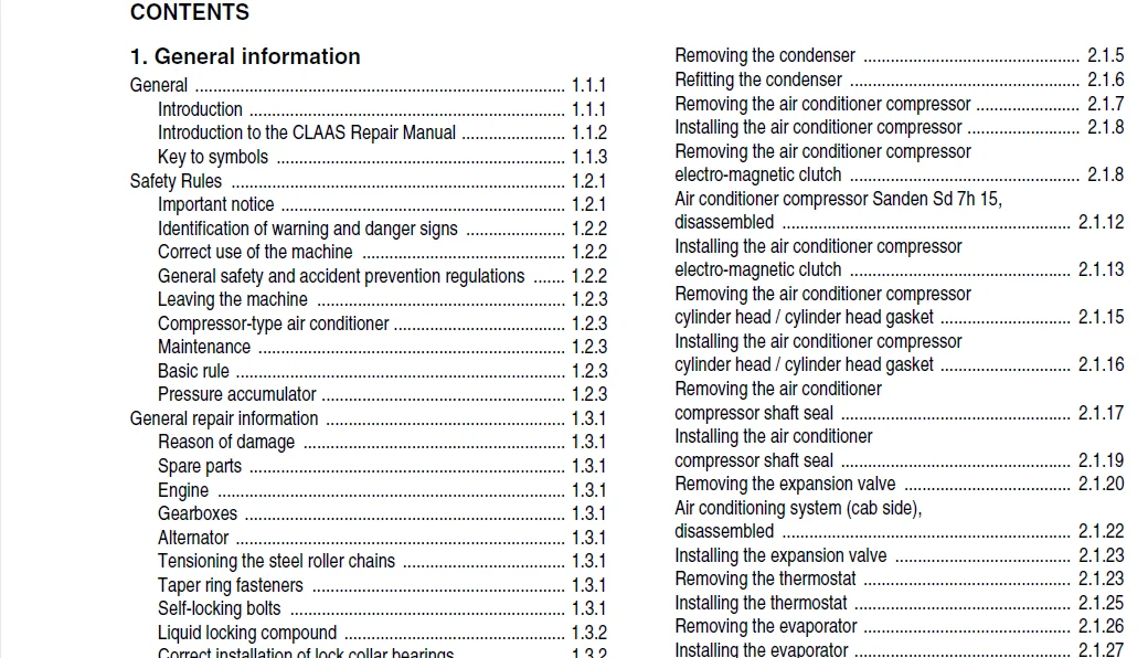
1 General information
General 111
Introduction 111
Introduction to the CLAAS Repair Manual 112
Key to symbols 113
Safety Rules 121
Important notice 121
Identification of warning and danger signs 122
Correct use of the machine 122
General safety and accident prevention regulations 122
Leaving the machine 123
Compressor-type air conditioner 123
Maintenance 123
Basic rule 123
Pressure accumulator 123
General repair information 131
Reason of damage 131
Spare parts 131
Engine 131
Gearboxes 131
Alternator 131
Tensioning the steel roller chains 131
Taper ring fasteners 131
Self-locking bolts 131
Liquid locking compound 132
Correct installation of lock collar bearings 132
Correct installation of adapter sleeve bearings 132
Ferrule fittings on hydraulic lines 132
Progressive ring fittings on hydraulic lines 133
Taper fittings on hydraulic lines 133
Welding 134
Some advice for speedy and correct repair work 134
Tightening torques 141
Bolts 141
Hydraulic fittings 142
Brake line screw joints 143
Wheel bolts 144
Safety features 144
Specifications 151
Lubricants chart 151
Hydraulic pressure values 152
Sectional view of machine 161
Drive diagram 171
Drive diagram, left-hand 171
Drive system diagram, right-hand side 172
2 Operator’s platform
Air conditioner 211
Important instructions regarding
the compressor-type air conditioning system 211
Important instructions regarding the installation
of parts in the compressor-type air conditioner 212
Air conditioning system – Topping up refrigerant 213
Checking / topping up the refrigerant oil level
at the air conditioner compressor 214
Topping up refrigerant oil 215
Removing the condenser 215
Refitting the condenser 216
Removing the air conditioner compressor 217
Installing the air conditioner compressor 218
Removing the air conditioner compressor
electro-magnetic clutch 218
Air conditioner compressor Sanden Sd 7h 15,
disassembled 2112
Installing the air conditioner compressor
electro-magnetic clutch 2113
Removing the air conditioner compressor
cylinder head / cylinder head gasket 2115
Installing the air conditioner compressor
cylinder head / cylinder head gasket 2116
Removing the air conditioner
compressor shaft seal 2117
Installing the air conditioner
compressor shaft seal 2119
Removing the expansion valve 2120
Air conditioning system (cab side),
disassembled 2122
Installing the expansion valve 2123
Removing the thermostat 2123
Installing the thermostat 2125
Removing the evaporator 2126
Installing the evaporator 2127
Removing the filter receiver drier 2129
Filter receiver drier, disassembled 2130
Installing the filter receiver drier 2130
Steering 221
Scenes of failures on the Orbitrol steering unit 221
External leaks 221
Internal leaks 221
Removing the steering column 222
Disassembling the steering column 224
Steering column, disassembled 227
Assembling the steering column 228
Installing the steering column 229
Removing the valve block from the Orbitrol 2211
Installing the valve block on the Orbitrol 2212
Removing the Orbitrol 2214
Orbitrol, disassembled 2214
Installing the Orbitrol 2215
Parking brake 231
Removing the parking brake 231
Installing the parking brake 232
Foot brake 241
Removing the master brake cylinder 241
Master brake cylinder, disassembled 241
Assembling the master brake cylinder 241
Installing the master brake cylinder 242
Adjusting the master brake cylinder 242
Engine electric system 251
Alternator 251
Contents
012 RHB LEXION 480 – 188 6781
Contents
3 Threshing mechanism
Feed rake conveyor 311
Removing the feed rake conveyor 311
Installing the feed rake conveyor 313
Removing the intercepting piece 314
Installing the intercepting piece 314
Removing the feed rake conveyor
suction blower 315
Disassembling the feed rake conveyor
suction blower 315
Feed rake conveyor suction blower,
disassembled 317
Assembling the feed rake conveyor
suction blower 318
Installing the feed rake conveyor
suction blower 319
Removing the top feed rake shaft 319
Feed rake top shaft, disassembled 3114
Installing the feed rake top shaft 3115
Removing the bottom feed rake roller 3119
Bottom feed rake roller, disassembled 3121
Assembling the bottom feed rake roller 3121
Installing the bottom feed rake roller 3121
Replacing the wooden ledges 3122
Removing the intermediate floor 3123
Installing the intermediate floor 3125
Replacing the runners 3125
Removing the intermediate drive shaft 3126
Intermediate drive shaft, disassembled 3130
Installing the intermediate drive shaft 3131
Removing the reverser drive 3132
Reverser drive, disassembled 3134
Installing the reverser drive 3135
Replacing the feeder chains 3135
Threshing concave 321
Removing the stone trap 321
Installing the stone trap 321
Removing the preconcave 322
Preconcave, disassembled 325
Installing the preconcave 326
Removing the main concave 327
Main concave, disassembled 3210
Installing the main concave 3212
Basic concave setting 3216
Adjusting the concave potentiometer 3221
Learning the limit stops 3221
Learning the limit stops 3222
Accelerator 331
Removing the bearing assembly and
the shaft on the right-hand side 331
Disassembling the right-hand bearing assembly 333
Assembling the right-hand bearing 333
Installing the right-hand bearing assembly
and shaft 335
Removing the bearing assembly
on the left-hand side 338
Disassembling the left-hand bearing assembly 3310
Assembling the left-hand bearing assembly 3311
Installing the left-hand bearing assembly 3312
Replacing the accelerator caps 3313
Removing the accelerator 3314
Accelerator, disassembled 3317
Installing the accelerator 3318
Threshing drum 341
Removing the right-hand drum bearing assembly 341
Disassembling the right-hand drum bearing 343
Right-hand drum bearing, disassembled 344
Installing the right-hand drum bearing 345
Removing the left-hand drum bearing assembly 346
Disassembling the left-hand drum bearing 348
Left-hand drum bearing assembly,
disassembled 348
Installing the left-hand drum bearing assembly 349
Removing the threshing drum 3410
Threshing drum, disassembled 3412
Renewing the beater bars 3413
Removing the threshing drum shaft 3414
Installing the threshing drum shaft 3416
Installing the threshing drum 3417
Impeller 351
Removing the right-hand impeller bearing 351
Installing the right-hand impeller bearing 353
Removing the left-hand impeller bearing 353
Installing the left-hand impeller bearing 355
Removing the impeller 356
Installing the impeller 358
Removing the flanged shaft
(from serial no ) 359
Impeller disassembled
(from serial no ) 3510
Installing the flanged shaft 3511
Removing the impeller shaft
(up to serial no ) 3512
Impeller disassembled
(up to serial no ) 3513
Installing the impeller shaft
(up to serial no ) 3514
Axial rotors 361
Removing the separation grates 361
Installing the separation grates 363
Removing the separating jacket 363
Installing the separating jacket 366
Removing the axial rotor supporting arm 367
Disassembling the axial rotor supporting arm 368
Supporting arm, disassembled 369
Installing the axial rotor supporting arm 369
Removing the axial rotor 3611
Installing the axial rotor 3613
Removing the hybrid unit completely 3614
Installing the hybrid unit 3622
4 Cleaning unit
Return pan 411
Lowering the return pan
(from serial no ) 411
Raising and installing the return pan
(from serial no ) 412
188 6781 – RHB LEXION 480 013
Contents
Removing the return pan 413
Rear rocker arm, disassembled 415
Installing the return pan 415
Sieve pan 421
Removing and installing the sieves 421
Removing the upper sieves
(from serial no ) 421
Removing the lower sieves
(from serial no ) 423
Installing the sieves
(from serial no ) 424
Tightening torques of axial mountings
for the upper and lower sieves
(from serial no ) 424
Sieves – Basic setting
(electric sieve adjustment – from serial no ) 425
Removing the upper sieves
(up to serial no ) 425
Removing the lower sieves
(up to serial no ) 427
Installing the sieves
(up to serial no ) 428
Tightening torques of axial mountings
for the upper and lower sieves
(up to serial no ) 429
Sieves – Basic setting
(electric sieve adjustment – up to serial no ) 429
Removing the 3-D upper sieve frame 4210
3-D upper sieve frame, disassembled 4215
Installing the 3-D upper sieve frame 4216
Removing the sieve pan 4217
Sieve pan, disassembled 4220
Installing the sieve pan 4221
Checking and adjusting the alignment
of preparation floor and sieve pan 4224
Preparation floor 431
Removing the preparation floor 431
Preparation floor, disassembled 433
Installing the preparation floor 434
3-D sieve pan control system 441
Adjusting the 3-D sieve pan control system 441
Adjusting pivot arm (A) with the “3-D gauge” 442
Rocker arm drive 451
Removing the intermediate drive shaft
for the rocker arm drive 451
Intermediate drive shaft for rocker arm drive,
disassembled 452
Installing the intermediate drive shaft
for the rocker arm drive 453
Cleaning fan 461
Removing the bearings of the cleaning fan 461
Cleaning fan bearing, disassembled 464
Installing the cleaning fan bearing 464
Removing the cleaning fan shaft 465
Removing the centre cleaning fan bearing 469
Centre cleaning fan bearing, disassembled 469
Installing the cleaning fan shaft 4610
Removing the cleaning fan rotors 4611
Installing the cleaning fan rotors 4611
Removing the cleaning fan housing 4612
Installing the cleaning fan housing 4614
5 Grain delivery
Returns elevator 511
Removing the returns elevator chain 511
Installing the returns elevator chain 513
Removing the top returns auger 513
Installing the top returns auger 515
Removing the returns elevator 516
Disassembling the returns elevator 517
Assembling the returns elevator 519
Installing the returns elevator 519
Removing the returns elevator boot 5110
Installing the returns elevator boot 5111
Removing the lower returns auger 5111
Installing the lower returns auger 5113
Grain elevator 521
Removing the clean grain elevator chain 521
Installing the clean grain elevator chain 522
Removing the clean grain elevator head 523
Dismantling the clean grain elevator head 524
Clean grain elevator head, disassembled 526
Assembling and installing the clean grain
elevator head 527
Removing the clean grain elevator shaft 527
Installing the grain elevator shaft 528
Removing the clean grain elevator boot 529
Installing the clean grain elevator boot 5210
Removing the clean grain auger 5210
Installing the clean grain auger 5213
Removing the grain tank filler auger 5214
Removing the grain tank filler auger
angle drive 5215
Disassembling the grain tank filler auger
angle drive 5216
Grain tank filler auger, disassembled 5217
Installing the grain tank filler auger 5218
Grain tank unloading 531
Removing the grain tank cross auger 531
Grain tank cross augers, disassembled 534
Installing the grain tank cross auger 535
Removing the vertical grain tank
unloading auger 537
Installing the vertical grain tank
unloading auger 5310
Removing the horizontal grain tank
unloading auger 5311
Installing the horizontal grain tank
unloading auger 5313
Removing the lower grain tank
unloading angle drive
(from serial no ) 5313
Disassembling the lower grain tank
unloading angle drive
(from serial no ) 5315
014 RHB LEXION 480 – 188 6781
Contents
Lower grain tank unloading angle drive,
disassembled
(from serial no …) 5318
Assembling the lower grain tank
unloading angle drive
(from serial no ) 5319
Installing the lower grain tank
unloading angle drive
(from serial no ) 5322
Removing the lower grain tank
unloading angle drive
(up to serial no ) 5323
Disassembling the lower grain tank
unloading angle drive
(up to serial no ) 5324
Lower grain tank unloading angle drive,
disassembled
(up to serial no …) 5327
Assembling the lower grain tank
unloading angle drive
(up to serial no ) 5328
Installing the lower grain tank
unloading angle drive
(up to serial no ) 5331
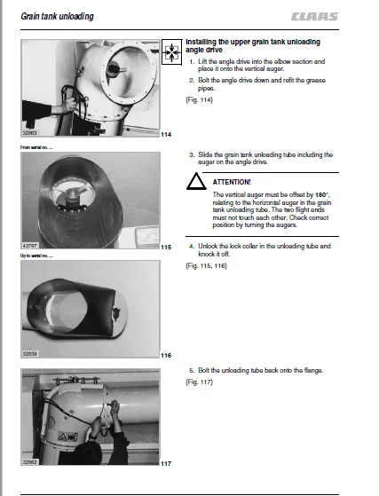
Removing the upper grain tank
unloading angle drive 5332
Disassembling the upper grain tank
unloading angle drive 5333
Upper grain tank unloading angle drive,
disassembled 5334
Assembling the upper grain tank
unloading angle drive 5335
Installing the upper grain tank
unloading angle drive 5338
Removing the grain tank unloading tube 5339
Refitting the unloading auger tube 5340
Removing the grain tank unloading tube elbow 5340
Installing the grain tank unloading tube elbow 5341
Removing the vertical unloading auger tube 5341
Installing the vertical unloading auger tube 5342
6 Straw discharge
Straw chopper 611
Removing the right-hand straw chopper bearing 611
Right-hand straw chopper bearing assembly,
disassembled 613
Installing the right-hand straw chopper bearing 613
Removing the left-hand straw chopper bearing 615
Left-hand straw chopper bearing assembly,
disassembled 616
Installing the left-hand straw chopper bearing 616
Removing the cutting cylinder 617
Cutting cylinder, disassembled 6111
Installing the cutting cylinder 6112
Replacing the free-swinging knives 6113
Uni-spreader 621
Removing the fan blade bearings 621
Assembling and installing the fan blade bearing 628
7 Drives
Drive belts 711
General Information 711
Drive diagram 712
Drive diagram, left-hand 712
Drive system diagram, right-hand side 713
Left-hand drive belts 721
Removing the cutterbar drive belt (1)
(Cutterbar drive without variable-speed drive) 721
Installing and adjusting the cutterbar drive belt (1)
(Cutterbar drive without variable-speed drive) 722
Removing the cutterbar drive belt (2)
(Cutterbar drive with variable-speed drive) 723
Installing and adjusting the cutterbar drive belt (2)
(Cutterbar drive with variable-speed drive) 724
Removing the cutterbar variable-speed
drive belt (3) 725
Installing and adjusting the cutterbar
variable-speed drive belt (3) 726
Removing the impeller drive belt (4) 727
Installing and adjusting the impeller drive
belt (4) 728
Removing the cutterbar intermediate drive belt (5) 729
Installing and adjusting the cutterbar
intermediate drive belt (5) 7210
Removing the uni-spreader hydraulic pump
drive belt (6) 7211
Installing and adjusting the uni-spreader
hydraulic pump drive belt (6) 7211
Removing the main intermediate drive belt (7) 7212
Installing and adjusting the main
intermediate drive belt (7) 7214
Removing the grain tank unloading
intermediate drive belt (8) 7216
Installing and adjusting the grain tank
unloading intermediate drive belt (8) 7217
Removing the straw chopper
intermediate drive belt (9) 7218
Installing and adjusting the straw chopper
intermediate drive belt (9) 7219
Removing the straw chopper drive
belts (10 and 11) 7220
Installing and adjusting the straw chopper
drive belts (10 and 11) 7222
Removing the uni-spreader
intermediate drive belt (12) 7223
Installing and adjusting the uni-spreader
intermediate drive belt (12) 7224
Removing the sieve pan intermediate
drive belt (13) 7225
Installing and adjusting the sieve pan
intermediate drive belt (13) 7226
Removing the sieve pan intermediate
drive belt (14) 7227
Installing and adjusting the sieve pan
intermediate drive belt (14) 7228
Removing the sieve pan drive belt (15) 7229
188 6781 – RHB LEXION 480 015
Contents
Installing and adjusting the sieve pan
drive belt (15) 7231
Removing the uni-spreader drive belt (16) 7232
Installing and adjusting the uni-spreader
drive belt (16) 7233
Removing the grain tank unloading
drive chain (17) 7234
Installing and adjusting the grain tank
unloading drive chain (17) 7235
Right-hand drive belts 731
Adjusting the axial rotor step drive (18) 731
Adjusting the axial rotor intermediate
drive (19) 732
Removing the fan intermediate drive belt (20) 733
Installing and adjusting the fan
intermediate drive belt (20) 734
Removing the fan drive belt (21) 735
Installing and adjusting the fan drive belt (21) 735
Removing the threshing mechanism
variable-speed drive belt (22) 736
Installing and adjusting the threshing
mechanism variable-speed drive belt (22) 737
Removing the threshing drum drive belt (23) 738
Installing and adjusting the threshing
drum drive belt (23) 739
Removing the accelerator drive belt (24) 7310
Installing and adjusting the accelerator
drive belt (24) 7311
Removing the radiator chaff screen
intermediate drive belt (25) 7312
Installing and adjusting the rotary chaff screen
intermediate drive belt (25) 7313
Removing the radiator chaff screen drive
belt (26) 7314
Installing and adjusting the rotary chaff screen
drive belt (26) 7314
Removing the fan drive belt (27) 7315
Installing and adjusting the fan drive belt (27) 7316
Removing the suction blower drive belt (28) 7317
Installing and adjusting the suction blower
drive belt (28) 7318
Removing the air conditioner compressor
drive belt (29) 7319
Installing and adjusting the air conditioner
compressor drive belt (29) 7320
Removing the compressed-air compressor
drive belt (30) 7321
Installing and adjusting the compressed-air
compressor drive belt (30) 7322
Removing the alternator drive belt (31) 7323
Installing and adjusting the alternator
drive belt (31) 7324
Removing the feed rake conveyor suction
blower drive belt (34) 7326
Installing and adjusting the feed rake conveyor
suction blower drive belt (34) 7327
Removing the straw spreader drive belt (36) 7328
Installing and adjusting the straw spreader
drive belt (36) 7329
Cutterbar drive 741
Removing the front pulley of cutterbar
drive (1) 741
Installing the front pulley of cutterbar drive (1) 742
Removing the deflection pulley
of cutterbar drive (1) 742
Deflection pulley of cutterbar drive (1),
disassembled 743
Installing the deflection pulley
of cutterbar drive (1) 743
Removing the slip clutch of cutterbar drive (1) 743
Installing the slip clutch of cutterbar drive (1) 744
Replacing the slip clutch linings
of cutterbar drive (1) 745
Slip clutch of cutterbar drive (1), dismantled 745
Removing the jockey pulley of cutterbar
drive (1) 747
Jockey pulley of cutterbar drive (1),
disassembled 747
Removing the rear pulley of cutterbar drive (1)
(up to serial no ) 747
Dismantling the rear pulley of cutterbar drive (1)
(up to serial no ) 7410
Rear pulley of cutterbar drive (1), disassembled
(up to serial no ) 7412
Assembling the rear pulley of cutterbar drive (1)
(up to serial no ) 7413
Installing the rear pulley of cutterbar drive (1)
(up to serial no ) 7415
Removing the rear pulley of cutterbar drive (1)
(from serial no ) 7417
Dismantling the rear pulley of cutterbar drive (1)
(from serial no ) 7420
Rear pulley of cutterbar drive (1), disassembled
(from serial no ) 7422
Assembling the rear pulley of cutterbar drive (1)
(from serial no ) 7423
Installing the rear pulley of cutterbar drive (1)
(from serial no ) 7424
Removing the cutterbar variable-speed
pulley assembly (spring-loaded) 7426
Disassembling the cutterbar variable-speed
pulley assembly (spring-loaded) 7427
Cutterbar variable-speed pulley assembly
(spring-loaded), disassembled 7430
Assembling the cutterbar variable-speed
pulley assembly (spring-loaded) 7431
Installing the cutterbar variable-speed
pulley assembly (spring-loaded) 7435
Removing the cutterbar drive V-belt pulley
when a cutterbar variable-speed drive is fitted 7437
Disassembling the cutterbar drive V-belt pulley
when a cutterbar variable-speed drive is fitted 7437
Cutterbar drive V-belt pulley with a cutterbar
variable-speed drive fitted, disassembled 7439
016 RHB LEXION 480 – 188 6781
Contents
Assembling the cutterbar drive V-belt pulley
with a cutterbar variable-speed drive fitted 7440
Installing the cutterbar drive V-belt pulley
with a cutterbar variable-speed drive fitted 7442
Removing and disassembling the cutterbar drive
deflection pulley (2) with a cutterbar
variable-speed drive fitted 7442
Assembling and installing the cutterbar drive
deflection pulley (2) with a cutterbar
variable-speed drive fitted 7443
Removing the cutterbar variable-speed
pulley assembly (hydraulic) 7443
Disassembling the cutterbar variable-speed
pulley assembly (hydraulic) 7446
Cutterbar variable-speed pulley assembly
(hydraulic), disassembled 7448
Assembling the cutterbar variable-speed
pulley assembly (hydraulic) 7450
Installing the cutterbar variable-speed
pulley assembly (hydraulic) 7451
Removing the cutterbar clutch 7452
Cutterbar clutch, disassembled 7459
Installing the cutterbar clutch 7460
Left-hand threshing mechanism drive 751
Removing the threshing mechanism drive
pulley assembly 751
Threshing mechanism drive pulley assembly,
disassembled 757
Installing the threshing mechanism drive
pulley assembly 758
Right-hand threshing mechanism drive 761
Removing the threshing drum variable-speed
pulley assembly (hydraulic) 761
Disassembling the threshing drum
variable-speed pulley assembly (hydraulic) 762
Threshing drum variable-speed pulley assembly
(hydraulic), disassembled 764
Assembling the threshing drum variable-speed
pulley assembly (hydraulic) 766
Installing the threshing drum variable-speed
pulley assembly (hydraulic) 766
Removing the threshing drum variable-speed
pulley assembly (spring-loaded) 767
Disassembling the threshing drum
variable-speed pulley assembly (spring-loaded) 768
Threshing drum variable-speed pulley assembly
(spring-loaded), disassembled 7611
Assembling the threshing drum variable-speed
pulley assembly (spring-loaded) 7612
Installing the threshing drum variable-speed
pulley assembly (spring-loaded) 7616
Removing the threshing mechanism
drive pulley 7618
Disassembling the threshing mechanism
drive pulley 7618
Threshing mechanism drive pulley,
disassembled 7620
Assembling the threshing mechanism
drive pulley 7621
Installing the threshing mechanism
drive pulley 7623
Threshing drum reduction gearbox 771
Removing the threshing drum
reduction gearbox 771
Disassembling the threshing drum
reduction gearbox 772
Threshing drum reduction gearbox,
disassembled 776
Assembling the threshing drum
reduction gearbox 778
Installing the threshing drum
reduction gearbox 7711
Threshing mechanism intermediate drive 781
Removing the right-hand intermediate
drive shaft bearing 781
Installing the right-hand intermediate
drive shaft bearing 782
Removing the left-hand intermediate
drive shaft bearing 782
Installing the left-hand intermediate
drive shaft bearing 783
Removing the intermediate drive shaft 784
Installing the intermediate drive shaft 784
Grain tank unloading drive 791
Removing the grain tank unloading
drive pulley 791
Installing the grain tank unloading
drive pulley 793
Chopper drive 7101
Removing the stage 1 chopper
drive V-belt pulley 7101
Stage 1 chopper drive V-belt pulley,
disassembled 7103
Assembling and installing the stage 1
chopper drive V-belt pulley 7104
Removing the stage 2 chopper
drive V-belt pulley 7106
Stage 2 chopper drive V-belt pulley,
disassembled 7108
Assembling and installing the stage 2 chopper
drive V-belt pulley 7109
Removing the jockey pulley of
straw chopper drive (10) 71011
Jockey pulley of straw chopper drive (10),
disassembled 71011
Assembling and installing the jockey pulley
of straw chopper drive (10) 71011
Removing the jockey pulley of
straw chopper drive (11) 71012
Jockey pulley of straw chopper drive (11),
disassembled 71012
Assembling and installing the jockey pulley
of straw chopper drive (11) 71013
Removing the stage 3 chopper
drive V-belt pulley 71013
188 6781 – RHB LEXION 480 017
Contents
Disassembling the stage 3 chopper
drive V-belt pulley 71015
Stage 3 chopper drive V-belt pulley,
dismantled 71017
Assembling and installing the stage 3 chopper
drive V-belt pulley 71018
Straw spreader drive 7111
Removing the straw spreader bearing housing 7111
Disassembling the straw spreader bearing housing 7112
Straw spreader bearing housing, disassembled 7115
Assembling the straw spreader bearing housing 7117
Installing the straw spreader bearing housing 7119
Uni-spreader drive 7121
Removing the uni-spreader drive angle drive 7121
Mounting the uni-spreader drive angle drive 7122
Sieve pan drive 7131
Removing the sieve pan drive V-belt pulley 7131
Sieve pan drive V-belt pulley, disassembled 7132
Installing the sieve pan drive V-belt pulley 7133
Removing the front sieve pan drive
deflection pulley 7134
Front sieve pan drive deflection pulley,
disassembled 7134
Assembling the front sieve pan drive
deflection pulley 7135
Installing the front sieve pan drive
deflection pulley 7135
Removing the rear sieve pan drive
deflection pulley 7135
Rear sieve pan drive deflection pulley,
disassembled 7136
Assembling the rear sieve pan drive
deflection pulley 7137
Installing the rear sieve pan drive
deflection pulley 7137
Fan drive 7141
Removing the stage 1 fan drive V-belt pulley 7141
Stage 1 fan drive V-belt pulley, disassembled 7141
Installing the stage 1 fan drive V-belt pulley 7141
Fan adjustment (electric) 7142
Fan adjustment (electric)
Version 1
(up to serial no ) 7143
Fan adjustment (electric)
Version 2
(from serial no …, up to serial no …) 7144
Fan adjustment (electric)
Version 3
(from serial no ) 7145
Removing the fan adjustment (electric)
(Version 1) 7146
Disassembling the fan adjustment (electric)
(Version 1) 7147
Fan adjustment (electric), disassembled
(Version 1) 7149
Assembling the fan adjustment (electric)
(Version 1) 71410
Installing the fan adjustment (electric)
(Version 1) 71412
Removing the fan adjustment (electric)
(Version 1, version 3) 71414
Disassembling the fan adjustment (electric)
(Version 1, version 3) 71415
Fan adjustment (electric), disassembled
(Version 1, version 3) 71417
Assembling the fan adjustment (electric)
(Version 1, version 3) 71418
Installing the fan adjustment (electric)
(Version 1, version 3) 71420
Removing the fan adjustment (electric)
(Version 2) 71422
Disassembling the fan adjustment (electric)
(Version 2) 71423
Fan adjustment (electric), disassembled
(Version 2) 71425
Assembling the fan adjustment (electric)
(Version 2) 71426
Installing the fan adjustment (electric)
(Version 2) 71429
Removing the fan variable-speed drive
(electric) 71431
Electric fan variable-speed pulley assembly,
disassembled 71432
Assembling and installing the electric fan
variable-speed pulley assembly 71433
Removing the fan drive jockey pulley (20) 71436
Fan drive jockey pulley (20), disassembled 71436
Installing the fan drive jockey pulley (20) 71437
Removing the fan variable-speed
pulley assembly (spring-loaded) 71437
Disassembling the fan drive variable-speed
pulley assembly (spring-loaded) 71438
Fan variable-speed pulley assembly
(spring-loaded), disassembled 71440
Assembling the fan variable-speed
pulley assembly (spring-loaded) 71441
Installing and adjusting the fan variable-speed
pulley assembly (spring-loaded) 71442
Axial rotor drive 7151
Removing the axial rotor intermediate
drive V-belt pulley 7151
Axial rotor intermediate drive V-belt pulley,
disassembled 7153
Assembling and installing the axial rotor
intermediate drive V-belt pulley 7154
Removing the axial rotors drive jockey
pulley (18) 7156
Axial rotor drive jockey pulley (18),
disassembled 7156
Installing the axial rotors drive jockey
pulley (18) 7157
Removing the bearings of axial rotors
drive (18) 7157
Bearing of axial rotors drive (18),
disassembled 7159
018 RHB LEXION 480 – 188 6781
Contents
Installing the bearings of axial rotors
drive (18) 71510
Removing the axial rotors drive 71511
Disassembling the axial rotor gearbox 71512
Axial rotor gearbox, disassembled 71515
Assembling the axial rotor gearbox 71516
Installing the axial rotor gearbox 71520
Engine output 7161
Removing the engine output pulley 7161
Installing the engine output pulley 7161
Removing the transfer gearbox 7162
Disassembling the transfer gearbox 7167
Transfer gearbox, disassembled 71611
Assembling the transfer gearbox 71612
Installing the transfer gearbox 71619
Rotary screen drive 7171
Removing the rotary screen drive 7171
Disassembling the rotary screen drive 7171
Rotary screen drive, disassembled 7173
Assembling and installing the rotary screen drive 7174
Removing the fan drive 7175
Installing the fan drive 7175
Final drives 7181
Removing the final drive gearbox 7181
Disassembling the final drive gearbox 7181
Removing the wheel drive shaft 7181
Removing the intermediate shaft 7183
Removing the drive shaft 7185
Final drive gearbox, disassembled 7186
Assembling the final drive gearbox 7187
Installing the drive shaft 7187
Installing the intermediate shaft 7188
Installing the wheel drive shaft 71811
Disassembling the planetary
final drive gearbox 71815
Planetary final drive gearbox,
disassembled 71822
Assembling the planetary
final drive gearbox 71823
Installing the final drive gearbox 71827
Manual gearbox 7191
Removing the manual gearbox 7191
Disassembling the manual gearbox 7193
Removing the shifter rails 7193
Removing the drive shaft 7195
Removing the main shaft 7196
Removing the differential 7198
Disassembling the differential 7199
Differential, disassembled 71911
Assembling the differential 71911
Installing the differential 71913
Manual gearbox, disassembled 71915
Assembling the manual gearbox 71916
Installing the main shaft 71917
Installing the drive shaft 71918
Installing the shifter rails 71919
Installing the manual gearbox 71922
Servo gearshift 71925
Removing the shifter pistons 71925
Servo gearshift, disassembled 71927
Installing the shifter pistons 71927
Bleeding the shifter piston 71928
Brake 7201
Parking brake – Replacing the brake linings 7201
Bleeding the brake system 7202
Disc brake – Changing the brake pads 7202
Removing a brake calliper 7203
Installing a brake calliper 7204
Steering axle 7211
Removing the wheel bearing 7211
Wheel bearing, disassembled 7214
Installing the wheel bearing 7215
Removing the stub axle 7217
Stub axle, disassembled 72110
Installing the stub axle 72110
Setting the track width 72113
Adjusting the steering axle end stops 72115
Removing the steering axle 72116
Steering axle bearing, disassembled 72118
Installing the steering axle 72119
8 Machine body
Rotary screen 811
Removing the rotary screen 811
Disassembling the rotary screen 811
Rotary screen, disassembled 813
Assembling and installing the rotary screen 814
Trough and lateral panel, disassembled 816
Adjusting the trough and the lateral panel
(if suction blower with drive is fitted) 817
Removing the fan drive 818
Installing the fan drive 818
Removing the rotary screen suction blower 819
Disassembling the rotary screen suction blower 819
Rotary screen suction blower, disassembled 8111
Assembling and installing the rotary screen
suction blower 8112
Drive axle 821
Removing the drive axle 821
Installing the drive axle 824
9 Hydraulic system
Oil cooler 911
Removing the oil cooler 911
Installing the oil cooler 914
Maintenance 921
Hydraulic system 921
Checking the oil level 921
Changing the hydraulic oil 922
Filling instructions when changing the hydraulic oil 923
Hydraulic pumps 931
Removing the uni-spreader hydraulic pump 931
Disassembling the uni-spreader hydraulic pump 932
Uni-spreader hydraulic pump, disassembled 933
Assembling the uni-spreader hydraulic pump 933
Installing the uni-spreader hydraulic pump 934
Removing the ground drive hydraulic pump 934
188 6781 – RHB LEXION 480 019
Contents
Installing the ground drive hydraulic pump 937
Removing the hydraulic double pump 938
Installing the hydraulic double pump 938
Hydrostatic fixed displacement motors 941
Removing the ground drive hydrostatic fixed
displacement motor 941
Installing the ground drive hydrostatic fixed
displacement motor 943
Removing the reverser drive hydrostatic fixed
displacement motor 945
Reverser drive hydrostatic fixed
displacement motor, disassembled 948
Installing the reverser drive hydrostatic fixed
displacement motor 949
Hydraulic cylinders – High-pressure hydraulic circuit 951
Removing the cutterbar cross levelling
hydraulic cylinders 951
Disassembling the cutterbar cross levelling
hydraulic cylinders 951
Cutterbar cross levelling hydraulic cylinder,
disassembled 953
Assembling the cutterbar cross levelling
hydraulic cylinders 954
Installing the cutterbar cross levelling
hydraulic cylinders 954
Bleeding the cutterbar cross levelling
hydraulic cylinders 956
Removing the cutterbar hydraulic cylinders 957
Cutterbar hydraulic cylinders –
Replacing the seals 957
Disassembling the cutterbar hydraulic cylinders 958
Cutterbar hydraulic cylinder, disassembled 9510
Assembling the cutterbar hydraulic cylinder 9511
Installing the cutterbar hydraulic cylinders 9512
Adjusting the cutterbar hydraulic cylinders 9512
Removing the cutterbar variable-speed drive
hydraulic cylinder 9513
Installing the cutterbar variable-speed drive
hydraulic cylinder 9514
Disassembling the rotary coupling 9514
Rotary coupling, disassembled 9516
Assembling the rotary coupling 9517
Removing the concave adjustment
hydraulic cylinder 9518
Disassembling the concave adjustment
hydraulic cylinder 9519
Concave adjustment hydraulic cylinder,
disassembled 9521
Assembling the concave adjustment
hydraulic cylinder 9522
Installing the concave adjustment
hydraulic cylinder 9523
Removing the grain tank unloading tube swing
hydraulic cylinder 9523
Disassembling the grain tank unloading
tube swing hydraulic cylinder 9523
Grain tank unloading tube swing
hydraulic cylinder, disassembled 9525
Assembling the grain tank unloading
tube swing hydraulic cylinder 9526
Installing the grain tank unloading tube swing
hydraulic cylinder 9527
Removing the straw chopper drive
hydraulic cylinder 9527
Disassembling the straw chopper drive
hydraulic cylinder 9528
Straw chopper drive hydraulic cylinder,
disassembled 9529
Assembling the straw chopper drive
hydraulic cylinder 9529
Installing the straw chopper drive
hydraulic cylinder 9530
Removing the threshing drum variable-speed
drive hydraulic cylinder 9530
Installing the threshing drum variable-speed
drive hydraulic cylinder 9531
Removing the reverser drive
hydraulic cylinder 9532
Disassembling the reverser drive
hydraulic cylinder 9532
Reverser drive hydraulic cylinder,
disassembled 9533
Assembling the reverser drive
hydraulic cylinder 9534
Installing the reverser drive
hydraulic cylinder 9534
Hydraulic cylinders for low-pressure hydraulics 961
Removing the threshing mechanism
engagement hydraulic cylinder 961
Disassembling the threshing mechanism
engagement hydraulic cylinder 962
Threshing mechanism engagement
hydraulic cylinder, disassembled 962
Assembling the threshing mechanism
engagement hydraulic cylinder 963
Installing the threshing mechanism
engagement hydraulic cylinder 964
Removing the grain tank unloading
engagement hydraulic cylinder 964
Disassembling the grain tank unloading
engagement hydraulic cylinder 965
Grain tank unloading engagement
hydraulic cylinder, disassembled 966
Assembling the grain tank unloading
engagement hydraulic cylinder 967
Installing the grain tank unloading
engagement hydraulic cylinder 968
Removing the engine speed control
hydraulic cylinder
(from serial no ) 969
Disassembling the engine speed control
hydraulic cylinder
(from serial no ) 969
Engine speed control hydraulic cylinder,
disassembled (from serial no ) 9611
0110 RHB LEXION 480 – 188 6781
Contents
Assembling the engine speed control
hydraulic cylinder
(from serial no ) 9612
Pre-setting the engine speed control
hydraulic cylinder
(from serial no ) 9614
Installing the engine speed control
hydraulic cylinder
(from serial no ) 9614
Setting the engine speed control
hydraulic cylinder
(from serial no ) 9615
Changing the road travel engine speed
(country variants 20 km/h and/or 25 km/h)
by converting the cylinder 9616
Conversion of cylinder to another country
variant (20 km/h and/or 25 km/h) 9616
Removing the engine speed control
hydraulic cylinder
(up to serial no ) 9619
Disassembling the engine speed control
hydraulic cylinder
(up to serial no ) 9620
Engine speed control hydraulic cylinder,
disassembled
(up to serial no …) 9623
Assembling the engine speed control
hydraulic cylinder
(up to serial no ) 9624
Pre-setting the engine speed control
hydraulic cylinder
(up to serial no ) 9625
Installing the engine speed control
hydraulic cylinder
(up to serial no ) 9625
Setting the engine speed control
hydraulic cylinder
(up to serial no ) 9626
Removing the 3-D sieve pan
hydraulic cylinder 9628
Disassembling the 3-D sieve pan
hydraulic cylinder 9628
3-D sieve pan hydraulic cylinder,
disassembled 9629
Assembling the 3-D sieve pan
hydraulic cylinder 9630
Installing the 3-D sieve pan
hydraulic cylinder 9631
Removing the pendulum control unit
of the 3-D sieve pan 9631
Disassembling the 3-D sieve pan
pendulum control unit 9631
Pendulum control unit of 3-D sieve pan,
disassembled 9633
Assembling the pendulum control unit
for 3-D sieve pan 9634
Installing the 3-D sieve pan pendulum
control unit 9634
Removing the yield meter moisture sensor
hydraulic cylinder 9635
Disassembling the yield meter moisture
sensor hydraulic cylinder 9636
Yield meter moisture sensor hydraulic cylinder,
disassembled 9637
Assembling the yield meter moisture
sensor hydraulic cylinder 9637
Installing the yield meter moisture
sensor hydraulic cylinder 9638
Checking and adjusting the yield meter
hydraulic cylinder 9638
Yield meter hydraulic cylinder,
disassembled 9640
Hydraulic cylinders – Steering hydraulics 971
Removing the steering cylinder 971
Disassembling the steering cylinder 971
Steering cylinder, disassembled 973
Assembling the steering cylinder 974
Installing the steering cylinder 975
Removing the Autopilot steering cylinder 975
Disassembling the Autopilot steering cylinder 976
Autopilot steering cylinder, disassembled 979
Assembling the Autopilot steering cylinder 9710
Installing the Autopilot steering cylinder 9711
Valve combinations 981
Removing the feeder reversing 3/2-way valve 981
Feeder reversing 3/2-way valve,
disassembled 981
Removing the cutterbar cross levelling
4/3-way valve 982
Cutterbar cross levelling 4/3-way valve,
disassembled 983
Removing the concave adjustment
pressure relief valve 984
Concave adjustment pressure relief valve,
disassembled 984
Assembling the concave adjustment
pressure relief valve 984
Removing the cutterbar and threshing drum
variable-speed drive 3/3-way valves 984
Cutterbar and threshing drum
variable-speed drive 3/3-way valve,
disassembled 986
Installing the cutterbar and threshing drum
variable-speed drive 3/3-way valves 987
Removing the threshing drum variable-speed
drive 3/3-way valve 987
Threshing drum variable-speed
drive 3/3-way valve, disassembled 988
Removing the concave, grain tank unloading
tube and straw chopper 4/3-way valves 989
Concave, grain tank unloading tube and
straw chopper 4/3-way valve, disassembled 9810
Assembling the concave, grain tank unloading
tube and straw chopper 4/3-way valves 9811
Installing the concave, grain tank unloading
tube and straw chopper 4/3-way valves 9811
188 6781 – RHB LEXION 480 0111
Contents
Removing the concave and grain tank
unloading tube 4/3 way valves 9811
Concave and grain tank unloading tube
4/3-way valve, disassembled 9813
Assembling the concave and grain tank
unloading tube 4/3-way valves 9814
Installing the concave and grain tank
unloading tube 4/3-way valves 9814
Removing the main valve 9814
Main valve, disassembled 9816
Assembling the main valve 9817
Installing the main valve 9817
Removing the CLAAS Autopilot
solenoid valve 9818
CLAAS Autopilot solenoid valve,
disassembled 9819
Assembling the CLAAS Autopilot
solenoid valve 9820
Installing the CLAAS Autopilot
solenoid valve 9820
Removing the low-pressure
solenoid valve block 9820
Low-pressure solenoid valve block,
disassembled 9822
Assembling the low-pressure
solenoid valve block 9823
Installing the low-pressure
solenoid valve block 9823
Removing the low-pressure solenoid valve
(yield meter) 9823
Yield meter 3/2-way solenoid valve,
disassembled 9825
Installing the low-pressure solenoid valve
(yield meter) 9826
10 Engine
Cooling system 1011
Removing the intercooler 1011
Installing the intercooler 1013
Removing the radiator 1013
Installing the radiator 1016
Fuel system 1021
Removing the fuel tank 1021
Installing the fuel tank 1022
Installing the additional fuel tank 1022
Installing the additional fuel tank 1024
Engine 1031
Removing the engine 1031
Installing the engine 1037
11 Index
Index 1111
IMAGES PREVIEW OF THE MANUAL:
CLAAS LEXION 480 REPAIR MANUAL – PDF DOWNLOAD:
PLEASE NOTE:
- This is the SAME manual used by the dealers to troubleshoot any faults in your vehicle. This can be yours in 2 minutes after the payment is made.
- Contact us at [email protected] should you have any queries before your purchase or that you need any other service / repair / parts operators manual.
S.M