CLAAS LEXION 560 550 LEXION 540 540 C LEXION 530 520 510 Operator’s Manual – PDF DOWNLOAD
Original price was: $89.95.$30.95Current price is: $30.95.
CLAAS LEXION 560 550 LEXION 540 540 C LEXION 530 520 510 Operator’s Manual – PDF DOWNLOAD
Description
CLAAS LEXION 560 550 LEXION 540 540 C LEXION 530 520 510 Operator’s Manual – PDF DOWNLOAD
DESCRIPTION:
CLAAS LEXION 560 550 LEXION 540 540 C LEXION 530 520 510 Operator’s Manual – PDF DOWNLOAD
The present Operator’s Manual applies to the CLAAS combine-harvesters
LEXION 560, type 584
LEXION 550, type 584
LEXION 540, type 584
LEXION 540 C, type 584
LEXION 530, type 583
LEXION 520, type 583
LEXION 510, type 583.
It is primarily intended for the machine operator and contains information on using, setting and operating the machine. In general, texts and pictures apply to all machine models covered by this manual. The information given applies equally, except where reference is made to a particular model in captions to the pictures or in the main text. Operation and maintenance of important accessories is also covered by this manual.
- A separate Operator’s Manual is available for cutterbars. Please read the instructions which apply to the appropriate accessories on your machine. Provided all instructions regarding maintenance and care of your machine are followed, you can count on many years of reliable service.
- Please have your authorised CLAAS dealer carry out the recommended regular inspections. The neglecting of regular maintenance and proper machine operation lead to reduced performance and loss of time. If proper operation and careful maintenance is ensured, your combine harvester, which incorporates latest harvesting technology, will render you excellent service.
This Operator’s Manual as well as the manuals listed below can be ordered from your CLAAS Dealer:
• Threshing Instructions for special crops
• Fitting and Operating Instructions for accessories
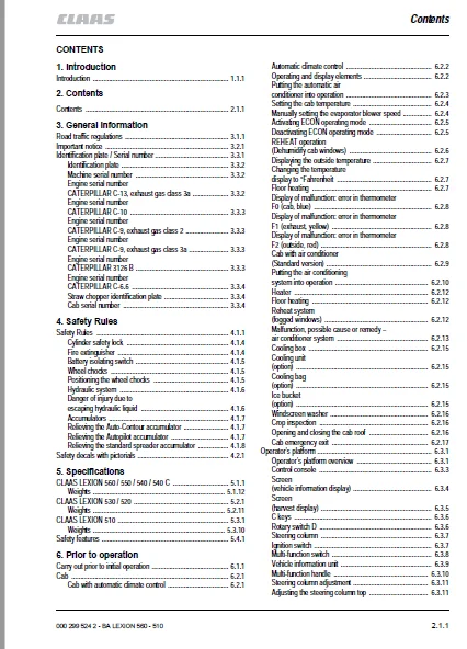
TABLE OF CONTENTS:
CLAAS LEXION 560 550 LEXION 540 540 C LEXION 530 520 510 Operator’s Manual – PDF DOWNLOAD
1 Introduction
Introduction 1 1 1
2 Contents
Contents 2 1 1
3 General Information
Road traffic regulations 3 1 1
Important notice 3 2 1
Identification plate / Serial number 3 3 1
Identification plate 3 3 2
Machine serial number 3 3 2
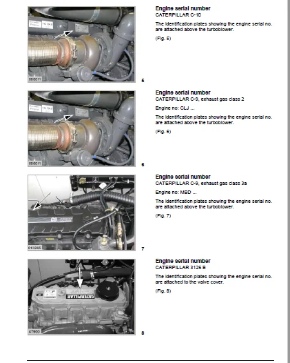
Engine serial number
CATERPILLAR C-13, exhaust gas class 3a 3 3 2
Engine serial number
CATERPILLAR C-10 3 3 3
Engine serial number
CATERPILLAR C-9, exhaust gas class 2 3 3 3
Engine serial number
CATERPILLAR C-9, exhaust gas class 3a 3 3 3
Engine serial number
CATERPILLAR 3126 B 3 3 3
Engine serial number
CATERPILLAR C-6 6 3 3 4
Straw chopper identification plate 3 3 4
Cab serial number 3 3 4
4 Safety Rules
Safety Rules 4 1 1
Cylinder safety lock 4 1 4
Fire extinguisher 4 1 4
Battery isolating switch 4 1 5
Wheel chocks 4 1 5
Positioning the wheel chocks 4 1 5
Hydraulic system 4 1 6
Danger of injury due to
escaping hydraulic liquid 4 1 6
Accumulators 4 1 7
Relieving the Auto-Contour accumulator 4 1 7
Relieving the Autopilot accumulator 4 1 7
Relieving the standard spreader accumulator 4 1 8
Safety decals with pictorials 4 2 1
5 Specifications
CLAAS LEXION 560 / 550 / 540 / 540 C 5 1 1
Weights 5 1 12
CLAAS LEXION 530 / 520 5 2 1
Weights 5 2 11
CLAAS LEXION 510 5 3 1
Weights 5 3 10
Safety features 5 4 1
6 Prior to operation
Carry out prior to initial operation 6 1 1
Cab 6 2 1
Cab with automatic climate control 6 2 1
Automatic climate control 6 2 2
Operating and display elements 6 2 2
Putting the automatic air
conditioner into operation 6 2 3
Setting the cab temperature 6 2 4
Manually setting the evaporator blower speed 6 2 4
Activating ECON operating mode 6 2 5
Deactivating ECON operating mode 6 2 5
REHEAT operation
(Dehumidify cab windows) 6 2 6
Displaying the outside temperature 6 2 7
Changing the temperature
display to °Fahrenheit 6 2 7
Floor heating 6 2 7
Display of malfunction: error in thermometer
F0 (cab, blue) 6 2 8
Display of malfunction: error in thermometer
F1 (exhaust, yellow) 6 2 8
Display of malfunction: error in thermometer
F2 (outside, red) 6 2 8
Cab with air conditioner
(Standard version) 6 2 9
Putting the air conditioning
system into operation 6 2 10
Heater 6 2 12
Floor heating 6 2 12
Reheat system
(fogged windows) 6 2 12
Malfunction, possible cause or remedy –
air conditioner system 6 2 13
Cooling box 6 2 15
Cooling unit
(option) 6 2 15
Cooling bag
(option) 6 2 15
Ice bucket
(option) 6 2 15
Windscreen washer 6 2 16
Crop inspection 6 2 16
Opening and closing the cab roof 6 2 16
Cab emergency exit 6 2 17
Operator’s platform 6 3 1
Operator’s platform overview 6 3 1
Control console 6 3 3
Screen
(vehicle information display) 6 3 4
Screen
(harvest display) 6 3 5
C keys 6 3 6
Rotary switch D 6 3 6
Steering column 6 3 7
Ignition switch 6 3 7
Multi-function switch 6 3 8
Vehicle information unit 6 3 9
Multi-function handle 6 3 10
Steering column adjustment 6 3 11
Adjusting the steering column top 6 3 11
2 1 2 BA LEXION 560 – 510 – 000 299 524 2
Contents
Steering wheel height adjustment 6 3 12
Central terminal compartment 6 3 12
Fuses 6 3 14
Relays 6 3 16
Operator’s seat 6 3 18
Operator’s seat, mechanical 6 3 18
Operator’s seat air suspension
(option) 6 3 21
Lighting and socket outlets 6 4 1
Headlights, working lights, mirrors 6 4 1
Sidefinder
(option) 6 4 7
Pathfinder lighting 6 4 7
Side position lights in case of excess width 6 4 8
Socket outlets 6 4 12
Access ladder 6 5 1
Access and ladder extension 6 5 1
Front ladder 6 5 5
Pre-assembling the ladder
(from serial no ) 6 5 5
Mounting the ladder 6 5 5
Swivelling the ladder
(up to serial no ) 6 5 8
Swivelling the ladder
(from serial no ) 6 5 9
Ladder starting protection 6 5 10
Rear ladder 6 5 11
Other uses of the rear ladder 6 5 12
Side panels 6 6 1
Opening and closing the side
panels and the tailgate 6 6 1
Opening the tailgate 6 6 2
Adjusting the gripping height
of the side panels 6 6 2
Adjusting the side panel lock 6 6 3
Tool cabinet 6 6 3
Toolbox 6 6 3
Folding down the tool cabinet 6 6 4
Mudguards / side panels 6 7 1
Installing the mudguards 6 7 1
Adapting the side panels
(Rice harvesting machines) 6 7 2
Rear axles 6 8 1
Adjustable rear drive axle
(2 60 m – 3 20 m) 6 8 2
Changing the adjustable rear drive axle 2 60 m – 3 20 m
from transport to working position 6 8 2
Adjusting the track width 6 8 4
Rear axle
(3 04 m) 6 8 8
Altering the 3 04 m rear axle
from transport to working position 6 8 8
Adjustable rear axle
(2 54 m – 2 99 m) 6 8 10
Changing the adjustable rear axle 2 54 m – 2 99 m
from transport to working position 6 8 10
Adjusting the track width 6 8 11
Additional weights of rear axle 6 9 1
Rear axle additional weights for
LEXION 560 – 540 6 9 1
Rear axle additional weights for
LEXION 530 – 510 6 9 2
Liquid filling for rear axle tyres 6 9 3
Installing the rear axle weights 6 9 3
Cutterbar hydraulic cylinders 6 10 1
Attaching cutterbar hydraulic cylinders 6 10 1
Number of cutterbar cylinders 6 10 1
Dual wheels 6 11 1
Mounting the dual wheels 6 11 1
Operating the front ladder
with dual tyres installed 6 11 4
Grain tank 6 12 1
Closing the grain tank drain holes 6 12 1
Opening the grain tank cover completely by hand
(8100 / 7800 / 7300 litres grain tank) 6 12 2
Driving the combine 6 13 1
Engine speed rotary switch 6 13 1
Average engine idle speed 6 13 1
Starting the engine 6 13 2
Forward travel / reverse travel 6 13 2
Gear selection 6 13 3
Adjusting the stiffness of ground
speed control lever 6 13 4
Stopping 6 13 4
Driving behaviour 6 13 4
Handling with cutterbar trailer 6 13 5
Steering 6 13 5
Brakes 6 13 5
Foot brake 6 13 5
Parking brake 6 13 6
Stopping the engine 6 13 7
Engaging/disengaging the
CLAAS 4-Trac system 6 13 7
Towing the machine 6 13 8
Emergency operation – Electro-hydraulic
gearshift (EHS) 6 13 9
Emergency operation decal 6 13 9
Engaging the neutral gearbox
position mechanically 6 13 10
Adjusting the initial gearbox position
(the gearbox can be shifted
electro-hydraulically again) 6 13 11
Engaging the neutral gearbox
position hydraulically 6 13 13
Engaging the 2nd gear hydraulically 6 13 13
CLAAS Autopilot
(Maize picker) 6 14 1
Putting the CLAAS Autopilot into operation 6 14 1
CLAAS Autopilot
(Grain cutterbar) 6 14 3
Adjusting the directional stability
of the combine harvester 6 14 3
Setting the laser sensor in the field 6 14 5
Rough adjustment 6 14 6
Fine adjustment 6 14 7
000 299 524 2 – BA LEXION 560 – 510 2 1 3
Contents
Laser sensor (crop edge has
moved out of visible range) 6 14 7
Adjusting the right laser sensor
(accessory) 6 14 8
Putting the CLAAS Autopilot into operation 6 14 9
Use in rape with left-hand side cutter 6 14 10
Towing 6 15 1
Towing the machine 6 15 1
Forward towing 6 15 1
Backward towing 6 15 1
7 Installing and removing the cutterbar
Installing the cutterbar 7 1 1
Tilting the cutterbar from transport position 7 1 1
Adjusting the cutterbar cross levelling hydraulic cylinder
(up to serial no ) 7 1 2
Machines equipped with Auto Contour 7 1 2
Adjusting the cutterbar cross levelling hydraulic cylinder
(from serial no ) 7 1 3
Machines equipped with Auto Contour 7 1 3
Aligning the coupling pin
(machines without Auto Contour) 7 1 3
Attaching the front attachment 7 1 4
Locking cutterbars and maize pickers
(Cutterbars without Auto Contour) 7 1 5
Connecting the universal drive shaft 7 1 6
Mounting the stands 7 1 7
Removing the cutterbar 7 2 1
Removing the universal coupling 7 2 1
Removing the universal drive shaft 7 2 1
Opening the cutterbar locking 7 2 2
Laying down the cutterbar on the ground 7 2 2
Placing the cutterbar on the cutterbar trailer 7 2 2
8 Operation CEBIS
Contents 8 1 1
CLAAS on-board information system (CEBIS) 8 2 1
CEBIS Monitor and rotary switch 8 2 3
C-keys 8 2 3
Rotary switch D 8 2 3
Multifunctional handle M 8 2 3
Window sections E
(Harvest display) 8 2 3
Flagging box 8 2 3
Rotary switch D 8 2 6
Prior-to-initial operation 8 2 7
Vehicle information display 8 2 9
Harvest display 8 2 9
Yield mapping 8 2 10
Flagging 8 2 11
GPS 8 2 13
Mapping ON/OFF 8 2 13
Mapping monitor 8 2 13
Load GPS data 8 2 13
Presettings reel 8 2 15
Reel horizontal position 8 2 15
Reel speed 8 2 15
Reel height 8 2 17
Presettings front attachment 8 2 19
Clearance between snapping plates 8 2 19
Cutterbar table length 8 2 19
Cutting height settings (CAC) 8 2 21
Cutting height settings for LEXION Montana 8 2 23
Partial width selection 8 2 25
Yield meter 8 2 26
Componentes 8 2 26
Basic setting and calibration 8 2 26
Preparation for yield measurement 8 2 27
Moisture measurement ON/OFF,
moisture correction, storage moisture 8 2 27
Quick guide to accurate measuring data 8 2 27
Yield measurement 8 2 29
Calibration factor 8 2 29
Set zero yield 8 2 29
Test-weighing 8 2 31
Weight measured 8 2 31
Moisture correction 8 2 31
Moisture mesaurement ON/OFF 8 2 31
Set zero angle 8 2 33
Storage moisture 8 2 33
Display dry yield 8 2 33
Setting combine to type of crop 8 2 35
List of threshable crops 8 2 35
Load CLAAS adjustments 8 2 35
Load own adjustments 8 2 37
Save own adjustments 8 2 37
Print machine adjustments 8 2 37
Display of CLAAS adjustments 8 2 37
Display of own adjustments 8 2 37
Cleaning by blowing 8 2 39
Recording harvest work 8 2 41
Planned work records 8 2 41
Next planned work record 8 2 41
Previous planned work record 8 2 43
New planned work record 8 2 43
Change a planned work record 8 2 43
Start / Stop 8 2 45
Completed work records 8 2 47
Next or previous completed work record 8 2 47
Restart a completed work record 8 2 47
Printer 8 2 47
Area correction 8 2 47
Daily recorder 8 2 49
Printing daily recordings 8 2 49
Clear daily recordings 8 2 49
Total recorder 8 2 51
Printing recorder summaries 8 2 51
Crop recorder 8 2 51
Copy the chip card 8 2 53
Adjustments 8 2 55
Cutterbar 8 2 55
Sensitivity CAC 8 2 55
Cutterbar upper and lower limits 8 2 57
Partial width proportions 8 2 57
Working position 8 2 57
Working width 8 2 59
2 1 4 BA LEXION 560 – 510 – 000 299 524 2
Contents
Auto reel height 8 2 59
Reel end stops 8 2 59
Cutterbar automatics 8 2 61
Cutterbar table length stops 8 2 61
Fore & aft reel adjustment stops 8 2 61
Vario automatics ON/OFF 8 2 63
Snapping plate end stops 8 2 63
Speeds 8 2 65
Learning speeds 8 2 65
Learning max no-load speed 8 2 65
Belt slip limit indicator 8 2 67
Chaff spreader speed monitor 8 2 67
Returns elevator speed monitor 8 2 67
Tachometer 8 2 69
Calibration run 8 2 69
Impulses/100 8 2 69
Sensitivity Autopilot 8 2 71
Zero Autopilot front attachment 8 2 71
Zero steering 8 2 71
Separation 8 2 73
Sensor test 8 2 73
Upper and lower sieve end stops 8 2 73
Upper and lower sieve adjustment 8 2 75
Returns limit 8 2 75
Set zero returns 8 2 75
CEBIS 8 2 77
Language 8 2 77
Date/Time 8 2 79
Display positive/negative 8 2 79
Measuring units 8 2 81
Version 8 2 81
Own display 8 2 83
Maintenance 8 2 85
XXh OK 8 2 85
XXh service list 8 2 85
Operator’s manual 8 2 87
Basic settings 8 2 87
Guide to adjustments 8 2 89
Problems/Remedies 8 2 89
CEBIS 8 2 91
Check list 8 2 91
Safety rules 8 2 91
Code protection 8 2 93
Engine load 8 2 95
Engine diagnosis 8 2 95
Alarms 8 2 96
Alerts 8 2 96
Problems / remedies – yield meter 8 2 97
Guide for impulses / 100 m 8 2 98
9 Operation – Basic machine
Feeder housing 9 1 1
Feeder chains 9 1 1
Front attachment reverser 9 1 2
Front attachment floatation springs 9 1 3
Checking the setting of the floatation springs 9 1 3
Cutting height indicator 9 1 4
Spring pressure indicator 9 1 5
Blocking the front attachment floatation springs
(Hydraulic lock) 9 1 5
Unlocking the front attachment floatation springs
(Hydraulic lock) 9 1 5
Blocking the front attachment floatation springs
(Mechanical lock) 9 1 6
Unlocking the front attachment floatation springs
(Mechanical lock) 9 1 6
Adjusting the drop rate of the front attachment 9 1 6
Engaging the front attachment
(switch console, up to serial no ) 9 1 7
Engaging the front attachment
(switch console, from serial no ) 9 1 7
Disengaging the front attachment
(switch console) 9 1 8
Front attachment QUICK STOP
(switch console) 9 1 8
Disengaging the front attachment
(multi-function handle) 9 1 9
Front attachment QUICK STOP
(multi-function handle) 9 1 9
Threshing mechanism 9 2 1
Stone trap
(small stone trap) 9 2 1
Stone trap
(large stone trap) 9 2 2
Engaging the threshing mechanism 9 2 3
Disengage the threshing mechanism 9 2 3
Threshing drum 9 2 4
Cleaning the threshing mechanism 9 2 4
Concave setting 9 2 5
Basic concave setting 9 2 5
Designations and dimensions for grain concave / maize
concave (small stone trap) 9 2 10
Designations and dimensions for grain concave / maize
concave (large stone trap) 9 2 11
Designations and dimensions on spike tooth concave
(small stone trap) 9 2 12
Designations and dimensions on spike tooth concave
(large stone trap) 9 2 13
Adjusting the concave position sensor 9 2 14
Threshing drum speed 9 2 15
Drum drives 9 2 15
Two-step variable-speed drive 9 2 15
Removing and installing the preconcave segments
(small stone trap) 9 2 16
Removing and installing the preconcave segments
(large stone trap) 9 2 18
Concave segment 9 2 19
Removing a concave segment
(small stone trap) 9 2 19
Installing the concave segment
(small stone trap) 9 2 20
Removing the concave segment
(large stone trap) 9 2 21
Installing the concave segment
(large stone trap) 9 2 22
Disawning 9 2 23
000 299 524 2 – BA LEXION 560 – 510 2 1 5
Contents
Unslugging the threshing drum 9 2 23
Deflector curtain 9 2 24
Adjusting the deflector curtain 9 2 25
Straw walker 9 3 1
Straw walker 9 3 1
Cleaning the straw walker 9 3 1
Warning signal 9 3 2
Multiple finger separation system 9 3 2
Straw walker performance monitor 9 3 3
Straw walker sensor 9 3 3
Straw walker risers 9 3 4
Rice risers 9 3 4
Centre riser 9 3 5
Side risers 9 3 6
Parallel risers 9 3 7
CCM risers 9 3 8
Cleaning
(Standard cleaning system) 9 4 1
Cleaning unit 9 4 1
Preparation floor 9 4 2
Frogmouth sieves 9 4 3
Electric sieve adjustment 9 4 3
Removing the sieves 9 4 4
Removing the upper sieves 9 4 4
Removing the lower sieves 9 4 6
Installing the sieves 9 4 7
Tightening torques of axial mountings
for the upper and lower sieves 9 4 7
Sieves – Basic setting 9 4 8
Harvesting without lower sieves 9 4 9
Covering the returns pan 9 4 9
Cleaning fan 9 4 9
Fan speed adjustment 9 4 10
Under-ventilated cleaning step
LEXION 560 – 520 9 4 10
Adjusting the pre-separation deflector
LEXION 560 – 520 9 4 10
Wind board
LEXION 560 – 520 9 4 11
Cleaning step
LEXION 510 9 4 11
Wind boards
LEXION 510 9 4 12
Fan shutters for threshing grass seed and similar crops
(accessory) 9 4 12
Dynamic slope compensation
(3-D cleaning system) 9 4 13
Returns 9 4 14
Inspecting the returns 9 4 14
Upper sieve performance monitor 9 4 15
Sieve pan sensor 9 4 15
Grain delivery 9 5 1
Augers and auger troughs 9 5 1
Elevators 9 5 2
Grain tank 9 5 3
Safety decal (0516 275 1) 9 5 3
Grain tank extension 9 5 4
Unloading the grain tank 9 5 5
Emergency unloading grain tank cover 9 5 6
Grain tank unloading aid
(accessory) 9 5 6
Grain tank unloading tube 9 5 7
Swinging the grain tank
unloading tube out and in 9 5 7
Grain tank unloading tube transport position 9 5 8
Cleaning covers on the grain
tank unloading tube 9 5 9
Shear bolt for grain tank unloading 9 5 9
Engaging and disengaging grain
tank unloading 9 5 10
Grain tank access 9 5 10
Automatic chain lubrication – grain tank unloading
(accessory) 9 5 11
Grain tank fill indicator 9 5 11
Straw chopper 9 6 1
Straw chopper 9 6 1
Before using the chopper for
the first time, check 9 6 1
Straw chopper with standard spreader 9 6 2
Putting the straw chopper into operation
(swinging the standard spreader to
chopping position) 9 6 2
Putting the straw chopper out of operation
(swinging the standard spreader to
swathing position) 9 6 3
Swinging the standard spreader to cutterbar
trailer transport position 9 6 4
Adjusting the cross blade 9 6 4
Adjusting the length of cut 9 6 5
Engaging the rasp bar
(accessory) 9 6 6
Adjusting the standard spreader spreading width
(up to serial no ) 9 6 6
Adjusting the standard spreader spreading width
(from serial no ) 9 6 7
Adjusting the height of standard spreader 9 6 8
Adjusting the spreading width centre
of standard spreader 9 6 9
Reducing the chopper speed 9 6 10
Chaff spreader / Straw spreader 9 7 1
Chaff spreader 9 7 1
Adjusting the chaff spreader speed 9 7 1
Adjusting the spreading width 9 7 2
Folding the chaff spreader open 9 7 2
Folding the chaff spreader in 9 7 4
Chaff spreader feed pan 9 7 4
Removing the chaff spreader feed pan 9 7 4
Installing the chaff spreader feed pan 9 7 5
Straw spreader 9 7 6
Adjusting the spreading width 9 7 6
Fitting the spreader rotors 9 7 6
LEXION 560 – 510 sieve charts and suggested
combine adjustments
(standard cleaning system) 9 8 1
LEXION 560 – 510 sieve chart
(standard cleaning system) 9 8 1
2 1 6 BA LEXION 560 – 510 – 000 299 524 2
Contents
LEXION 560 – 510 suggested combine adjustments
(standard cleaning system) 9 8 2
Disawning 9 9 1
Disawner plates 9 9 1
Concave segment 9 9 1
Malfunction, cause and / or remedy –
Basic machine 9 10 1
10 Maintenance – Basic machine
Important maintenance instructions 10 1 1
Important maintenance instructions
and safety rules 10 1 1
Front attachment 10 1 1
Correct tension of steel roller chains 10 1 1
Belts 10 1 2
Variable-speed drives 10 1 2
Bolts 10 1 2
Lubrication 10 1 2
Brakes 10 1 3
Wheels / tyres 10 1 4
Hydraulic system 10 1 5
Electrical system 10 1 6
Air conditioner 10 1 7
Safety guards / spare parts 10 1 8
Unbalance 10 1 8
Welding 10 1 9
Maintenance schedules and lubricants charts 10 2 1
Maintenance schedules 10 2 1
Lubricants charts 10 2 4
Hydraulic system 10 3 1
Accumulators 10 3 1
Checking the oil level 10 3 1
Change hydraulic oil 10 3 2
Changing the hydraulic oil filter 10 3 3
Saturation of hydraulic oil filter
(from serial no ) 10 3 3
Replacing the return filter
(up to serial no ) 10 3 4
Replacing the return filter
(from serial no ) 10 3 4
Filling instructions when replacing the hydraulic oil
(Sauer 90 R 130 / 90 M 100) 10 3 5
Bleeding the cutterbar cross levelling hydraulic cylinder
(up to serial no ) 10 3 5
Bleeding the cutterbar cross levelling hydraulic cylinder
(from serial no ) 10 3 7
Transmission / Brakes 10 4 1
Manual gearbox 10 4 1
Checking the oil level 10 4 1
Oil change 10 4 1
Final drive 19 t / two-step 10 4 2
Checking the oil level 10 4 2
Oil change 10 4 2
Final drive 21 t / single-step 10 4 2
Checking the oil level 10 4 2
Oil change 10 4 2
Final drive gearbox
(planetary gear) 10 4 3
Checking the oil level 10 4 3
Oil change 10 4 3
Threshing drum reduction gearbox 10 4 4
Oil change 10 4 4
Checking the oil level 10 4 4
Transfer gearbox
(engine) 10 4 5
Checking the oil level 10 4 5
Oil change 10 4 5
Grain tank unloading gearbox 10 4 5
Checking the oil level 10 4 5
Oil change 10 4 5
Foot brake and brake fluid 10 4 6
Parking brake 10 4 6
Feeder housing 10 5 1
Tension feeder chains 10 5 1
Cleaning the suction blower
(accessory) 10 5 2
Elevator chains 10 6 1
Tensioning the grain elevator chain
(machine without yield meter) 10 6 1
Tensioning/relieving the tension
of the grain elevator chain
(machine with yield meter) 10 6 2
Tensioning the returns elevator chain 10 6 2
Drive belts / drive chains 10 7 1
General Information 10 7 1
Drive system diagram, left-hand side 10 7 2
Drive belts, drive chains 10 7 2
Drive system diagram, right-hand side 10 7 3
Drive belts, drive chains 10 7 3
Removing the belt (1) 10 7 4
Installing the belt (1) 10 7 5
Removing the belt (2) 10 7 6
Installing the belt (2) 10 7 8
Removing the belt (3) 10 7 9
Installing the belt (3) 10 7 10
Removing the belt (4) 10 7 12
Installing the belt (4) 10 7 14
Removing the belt (5) 10 7 16
Installing the belt (5) 10 7 17
Removing the belt (6) 10 7 19
Installing the belt (6) 10 7 20
Removing the belt (7) 10 7 21
Installing the belt (7) 10 7 23
Removing the belt (8) 10 7 26
Installing the belt (8) 10 7 27
Removing the belt (9) 10 7 29
Installing the belt (9) 10 7 32
Removing the belt (10) 10 7 34
Installing the belt (10) 10 7 36
Removing the chain (11) 10 7 38
Installing the chain (11) 10 7 39
Removing the belt (12) 10 7 41
Installing the belt (12) 10 7 42
Removing the belt (13) 10 7 44
Installing the belt (13) 10 7 45
Removing the belt (14) 10 7 47
Installing the belt (14) 10 7 48
000 299 524 2 – BA LEXION 560 – 510 2 1 7
Contents
Removing the belt (17) 10 7 49
Installing the belt (17) 10 7 51
Removing the belt (18) 10 7 53
Installing the belt (18) 10 7 55
Removing the belt (19) 10 7 56
Installing the belt (19) 10 7 57
Removing the belt (20) 10 7 59
Installing the belt (20) 10 7 61
Removing the belt (22) 10 7 64
Installing the belt (22) 10 7 65
Removing the belt (45) 10 7 67
Installing the belt (45) 10 7 68
Removing the belt (46) 10 7 70
Installing the belt (46) 10 7 71
Removing the belt (48) 10 7 73
Installing the belt (48) 10 7 75
Removing the belt (51) 10 7 76
Installing the belt (51) 10 7 77
Removing the belt (52) 10 7 78
Installing the belt (52) 10 7 79
Removing the belt (53) 10 7 81
Installing the belt (53) 10 7 82
Removing the belt (54) 10 7 84
Installing the belt (54) 10 7 85
Removing the chain (55) 10 7 86
Installing the chain (55) 10 7 86
Installing the chain (56) 10 7 88
Removing the belt (57) 10 7 89
Installing the belt (57) 10 7 90
Remove belt (58)
(CATERPILLAR C9 / 3126 B) 10 7 92
Installing belt (58)
(CATERPILLAR C9 / 3126 B) 10 7 93
Removing belt (58)
(CATERPILLAR C10) 10 7 94
Installing the belt (58)
(CATERPILLAR C10) 10 7 95
Removing the belt (59) 10 7 96
Installing the belt (59) 10 7 97
Cab / air conditioner 10 8 1
Cab 10 8 1
Cleaning the filters 10 8 1
Cleaning the units located in the cab roof 10 8 1
Cleaning the cab screens 10 8 2
Air conditioner 10 8 3
Cleaning the condenser 10 8 3
Checking refrigerant level 10 8 3
Replacing the filter receiver drier 10 8 4
Required refrigerant quantity –
refrigerant R 134 a 10 8 4
Oil for the compressor 10 8 5
Maintenance work before the harvest 10 8 5
Fire extinguisher 10 9 1
Compressed-air system
(accessory) 10 10 1
Compressed air connections 10 10 2
Compressed-air gun and woven hose 10 10 2
Draining the accumulator 10 10 3
Pressure controller 10 10 3
Checking the safety valve 10 10 4
Straw chopper 10 11 1
Replacing the free-swinging knives for grain 10 11 1
Removing the straw guide plate 10 11 1
Installing the straw guide plate 10 11 3
Removing the free-swinging
knives for grain 10 11 5
Bolting down the free-swinging
knives for grain 10 11 5
Replacing the stationary knives 10 11 7
Winter storage instructions for combines 10 12 1
11 Maintenance – Engine
Important maintenance instructions 11 1 1
Important maintenance instructions
and safety rules 11 1 1
Maintenance schedules and lubricants charts 11 2 1
Maintenance schedule
CATERPILLAR C-10 / C-9 / 3126 B,
exhaust gas class 2 11 2 1
Lubricants chart
CATERPILLAR C-10 / C-9 / 3126 B,
exhaust gas class 2 11 2 2
Maintenance schedule
CATERPILLAR C-13 / C-9 / C-6 6,
exhaust gas class 3a 11 2 3
Lubricants chart
CATERPILLAR C-13, C-9, C-6 6,
exhaust gas class 3a 11 2 4
Engine maintenance 11 3 1
Engine overview
CATERPILLAR C-13 11 3 1
Engine overview
CATERPILLAR C-10 11 3 1
Engine overview
CATERPILLAR C-9
exhaust gas class 3a 11 3 2
Engine overview
CATERPILLAR C-9
exhaust gas class 2 11 3 2
Engine overview
CATERPILLAR C-6 6 11 3 3
Engine overview
CATERPILLAR 3126 B 11 3 3
Fuel system / engine oil 11 4 1
Fuel system 11 4 1
Fuel tank 11 4 1
Fuel tank breather
(from serial no ) 11 4 1
Fuel shut-off tap 11 4 2
Water separator / fuel prefilter
(standard equipment – small version) 11 4 2
Water separator / fuel pre-filter
(accessory, replaces fuel pre-filter Fig 5) 11 4 3
Replacing the fuel filter cartridge
(CATERPILLAR C-13 / C-10 / C-9 / 3126 B) 11 4 4
Replacing the fuel filter cartridge
(CATERPILLAR C-6 6) 11 4 5
2 1 8 BA LEXION 560 – 510 – 000 299 524 2
Contents
Bleeding the fuel system
(CATERPILLAR C-13 / C-10 / C-9 / 3126 B) 11 4 6
Manual fuel primer pump with fuel pre-cleaner
(CATERPILLAR C-6 6) 11 4 6
Engine oil level check 11 4 6
Engine oil change 11 4 7
Draining used oil 11 4 8
Oil filter 11 4 10
Topping up engine oil 11 4 12
Cooling system 11 5 1
Coolant 11 5 1
Water drain plugs on the engine block 11 5 1
Radiator 11 5 2
Filling the cooling system with coolant 11 5 3
Overpressure 11 5 3
Frost protection / corrosion protection 11 5 3
Warning sign 11 5 3
Coolant temperature 11 5 4
Shut down the overheated engine 11 5 4
Rotary chaff screen 11 5 5
Cleaning the radiator 11 5 7
Dry-type air filter 11 6 1
Warning device 11 6 2
Cleaning the air filter intake screen 11 6 2
Cleaning the air filter with plastic housing 11 6 3
Removing the air filter main cartridge 11 6 3
Cleaning the air filter main cartridge 11 6 4
Installing the air filter main cartridge 11 6 4
Cleaning the air filter with metal housing 11 6 5
Removing the air filter main cartridge 11 6 5
Cleaning the air filter main cartridge 11 6 6
Installing the air filter main cartridge 11 6 7
Safety filter cartridge 11 6 7
Removing and installing safety cartridge
(plastic housing) 11 6 8
Removing and installing safety cartridge
(metal housing) 11 6 9
Alternator 11 7 1
Cleaning the alternator 11 7 1
Electrical system 11 8 1
Battery 11 8 1
Alternator 11 8 2
Engine problems, cause and / or remedy 11 9 1
Engine winter storage 11 10 1
Engine preservation 11 10 1
12 Lubrication chart
Lubricants and lubrication instructions 12 1 1
13 Index
Index 13 1 1
CLAAS LEXION 560 550 LEXION 540 540 C LEXION 530 520 510 OPERATOR’S MANUAL – PDF DOWNLOAD:
IMAGES PREVIEW OF THE MANUAL:
PLEASE NOTE:
- This is not a physical manual but a digital manual – meaning no physical copy will be couriered to you. The manual can be yours in the next 2 mins as once you make the payment, you will be directed to the download page IMMEDIATELY.
- This is the same manual used by the dealers inorder to diagnose your vehicle of its faults.
- Require some other service manual or have any queries: please WRITE to us at [email protected]
S.V