Claas Lexion 580 Lexion 570 570C Operator’s Manual – PDF DOWNLOAD
Original price was: $89.95.$30.95Current price is: $30.95.
Claas Lexion 580 Lexion 570 570C Operator’s Manual – PDF DOWNLOAD
Description
Claas Lexion 580 Lexion 570 570C Operator’s Manual – PDF DOWNLOAD
DESCRIPTION:
Claas Lexion 580 Lexion 570 570C Operator’s Manual – PDF DOWNLOAD
How to use this manual :
This operator’s manual is the original operator’s manual. In the following texts, it will be referred to simply as the operator’s manual. This operator’s manual is intended for all users and provides information on the use, operation, adjustment, maintenance, cleaning and transportation of the machine.
- Provided all instructions regarding proper maintenance and operation of your machine are followed, you can count on many years of reliable service.
- Failure to perform maintenance or incorrect operation lead to an increased safety risk, premature wear, a reduction in performance, loss of earnings and time.
- Have the post harvest check / annual check performed regularly by your CLAAS dealer. A combination of the prescribed maintenance work with the post harvest check is recommended. If you use the latest expertise and experience that went into this machine, it will render you consistently excellent service.
TABLE OF CONTENTS:
Claas Lexion 580 Lexion 570 570C Operator’s Manual – PDF DOWNLOAD
1 Introduction
1 1 General Information 25
1 1 1 How to use this manual 25
1 1 2 Validity of Operator’s manual 27
2 General Information
2 1 Road traffic 28
2 2 Important notice 30
2 3 Identification plate / Serial number 31
2 3 1 Identification plate / Serial number 31
2 3 2 Identification plate 32
2 3 3 Machine serial number 32
2 3 4 Engine serial number 32
2 3 5 Straw chopper identification plate 33
2 3 6 Cab serial number 34
2 4 Attachment parts / machine body 35
2 4 1 Access to the workplace and maintenance areas 35
3 Safety Rules
3 1 Safety rules 38
3 1 1 General information 38
3 1 2 Identification of warning and danger signs 38
3 1 3 Intended use 39
3 1 4 Reasonable foreseeable misuse 40
3 1 5 General safety and accident prevention regulations 40
3 1 6 Transporting passengers, instructor, operating personnel 41
3 1 7 Driving operations 41
3 1 8 Automotive operation of combine harvester 42
3 1 9 Leaving the combine harvester 42
3 1 10 Front attachments (cutterbar etc ) and other components 42
3 1 11 Air conditioner 43
3 1 12 Maintenance 43
3 1 13 Basic rule 43
3 1 14 Accumulators 43
3 1 15 Decommissioning and disposal 44
3 1 16 Cylinder safety lock 44
3 1 17 Fire extinguisher 45
3 1 18 Battery isolating switch 46
3 1 19 Wheel chocks 46
3 1 20 Jack up the machine 47
3 1 21 Loading and tying down the machine 47
3 1 22 Hydraulic system 48
3 1 23 Danger of injury due to escaping hydraulic liquid 49
3 1 24 Accumulators 49
3 1 25 Relieving the concave adjustment accumulator 50
3 2 Safety decals with pictorials 51
3 2 1 General instructions for warning signs 51
6
69704
3 2 2 Safety decals 52
4 Specifications
4 1 CLAAS LEXION 580 84
4 1 1 Cab / Operator’s platform 84
4 1 2 Cutterbar 84
4 1 3 Threshing mechanism 85
4 1 4 Separation 85
4 1 5 Cleaning (Standard cleaning system) 86
4 1 6 Grain delivery 86
4 1 7 Engine 87
4 1 8 Chassis 88
4 1 9 Tyres and tyre pressures 89
4 1 10 Torque settings of wheel bolts 89
4 1 11 Track width 90
4 1 12 Transport position / Working position 93
4 1 13 Weights 96
4 1 14 Safety features 96
4 2 CLAAS LEXION 570 / 570 C 97
4 2 1 Cab / Operator’s platform 97
4 2 2 Cutterbar 97
4 2 3 Threshing mechanism 98
4 2 4 Separation 98
4 2 5 Cleaning (Standard cleaning system) 98
4 2 6 Cleaning (JET STREAM cleaning system) 99
4 2 7 Grain delivery 99
4 2 8 Engine 100
4 2 9 Chassis 101
4 2 10 Tyres and tyre pressures 102
4 2 11 Torque settings of wheel bolts 103
4 2 12 Track width 104
4 2 13 Transport position / Working position 107
4 2 14 Weights 110
4 2 15 Safety features 110
5 Prior to operation
5 1 General Information 111
5 1 1 Initial operation check list 111
5 1 2 Loading and tying down the machine 112
5 2 Cab 114
5 2 1 Cab with automatic air conditioner 114
5 2 2 Automatic air conditioner 116
5 2 3 Putting the automatic air conditioner into operation 117
5 2 4 Setting the cab temperature 118
5 2 5 Manually setting the evaporator blower speed 118
5 2 6 Activating ECON operating mode 119
5 2 7 Deactivating ECON operating mode 119
5 2 8 REHEAT operation (Dehumidify cab windows) 120
7
69704
5 2 9 Displaying the outside temperature 121
5 2 10 Changing the temperature display to °Fahrenheit 121
5 2 11 Floor heating 121
5 2 12 Display of malfunction – Error in thermometer F0 (cab, blue) 122
5 2 13 Display of malfunction – Error in thermometer F1 (exhaust, yellow) 122
5 2 14 Display of malfunction – Error in thermometer F2 (outside, red) 122
5 2 15 Cab with air conditioner (Standard version) 123
5 2 16 Putting the air conditioning system into operation 125
5 2 17 Heater 126
5 2 18 Floor heating 126
5 2 19 REHEAT operation (Dehumidify cab windows) 127
5 2 20 Problem, possible cause or remedy – air conditioner system 128
5 2 21 Cooling box 130
5 2 22 Cooling unit (option) 130
5 2 23 Cooling bag (option) 130
5 2 24 Ice bucket (option) 131
5 2 25 Windscreen washer 131
5 2 26 Crop inspection 131
5 2 27 Opening and closing the cab roof 132
5 2 28 Cab emergency exit 132
5 2 29 Operator’s platform overview 133
5 2 30 Control console 135
5 2 31 Screen (harvest display) 138
5 2 32 Screen (vehicle information display) 140
5 2 33 Keys C / Rotary switch D 142
5 2 34 Ignition switch 143
5 2 35 Multifunction switch 144
5 2 36 Vehicle information unit 145
5 2 37 Multifunction handle 146
5 2 38 Reel height limitation 147
5 2 39 Steering column adjustment 147
5 2 40 Steering wheel height adjustment 148
5 2 41 Central terminal compartment 149
5 2 42 Contents – Central terminal compartment (up to serial no ) 150
5 2 43 Fuses (up to serial no ) 151
5 2 44 Relays (up to serial no ) 153
5 2 45 Contents – Central terminal compartment (from serial no ) 156
5 2 46 Fuses (from serial no ) 157
5 2 47 Relays (from serial no ) 159
5 2 48 Operator’s seat 162
5 2 49 Operator’s seat, mechanical 162
5 2 50 Air-suspended driver’s seat 164
5 3 Lighting and socket outlets 167
5 3 1 Headlights, working lights, mirrors 167
5 3 2 Sidefinder (option) 173
5 3 3 Pathfinder lighting 173
5 3 4 Side position lights in case of excess width 174
8
69704
5 3 5 Socket outlet 12 V 176
5 3 6 CDS 5000 diagnosis connection socket outlet 178
5 4 Access ladder 179
5 4 1 Access and ladder extension 179
5 4 2 Pre-assembling the front ladder (from serial no ) 184
5 4 3 Installing the front ladder 184
5 4 4 Swivelling the front ladder (up to serial no ) 187
5 4 5 Swivelling the front ladder (from serial no ) 188
5 4 6 Ladder starting protection 190
5 4 7 Rear ladder 191
5 5 Side panels 193
5 5 1 Opening and closing the side panels and the tailgate 193
5 5 2 Opening the tailgate 194
5 5 3 Adjusting the gripping height of the side panels 195
5 5 4 Adjusting the side panel lock 196
5 5 5 Tool cabinet 196
5 6 Mud guards / Side panels / Hitch block / Transport trailer 198
5 6 1 Installing the mudguards 198
5 6 2 Adapting the side panels (Rice harvesting machines) 199
5 6 3 Fitting the hitch block 199
5 7 Rear axles (Standard cleaning system) 200
5 7 1 Overview of rear axle 200
5 7 2 Rear drive axle 000 660 287 0 200
5 7 3 Rear drive axle 000 694 760 1 201
5 7 4 Rear drive axle 000 669 835 6 201
5 7 5 Rear axle 000 770 920 1 201
5 7 6 Rear axle 000 768 705 1 202
5 7 7 Rear axle 000 769 610 3 202
5 7 8 Converting the rear drive axle from transport to working position 202
5 7 9 Rear drive axle – Adjusting the track width 203
5 7 10 Rear drive axle 000 694 760 1 – Adjusting the steering stop 207
5 7 11 Converting the rear axle 000 770 920 1 / 000 768 705 1
from transport to working position 208
5 7 12 Converting the rear axle 000 769 610 3 from transport to working position 210
5 8 Rear axles (JET STREAM cleaning system) 211
5 8 1 Overview of rear axle 211
5 8 2 Rear axle 000 769 155 1 211
5 8 3 Rear axle 000 769 100 1 212
5 8 4 Rear drive axle 000 694 900 2 212
5 8 5 Rear axle 000 768 980 1 212
5 8 6 Converting the rear axle 000 769 155 1 from transport to working position 213
5 8 7 Rear axle 000 769 155 1 – Track width 217
5 8 8 Rear axle 000 769 100 1 – Track width 218
5 8 9 Converting the rear drive axle 000 694 900 2 from transport to working position 218
5 8 10 Rear drive axle 000 770 589 2 – Adjusting the track width 221
5 8 11 Adjusting the rear drive axle 000 694 900 2 to the track width 223
5 8 12 Converting the rear axle 000 768 980 1 from transport to working position 224
5 8 13 Rear axle 000 768 980 1 – Adjusting the track width 227
9
69704
5 9 Additional weights of rear axle 229
5 9 1 Additional rear axle weights LEXION 580 Standard cleaning system 229
5 9 2 Additional rear axle weights LEXION 570 Standard cleaning system 230
5 9 3 Additional rear axle weights LEXION 570 / 570 C JET STREAM cleaning system 231
5 9 4 Liquid filling of rear axle tyres 232
5 9 5 Installing the rear axle weight 232
5 9 6 Shipping package – rear axle weight (Rear drive axle) 234
5 10 Cutterbar hydraulic cylinders 235
5 10 1 Fitting the cutterbar hydraulic cylinders with springs 235
5 10 2 Number of cutterbar cylinders (LEXION 580) 235
5 10 3 Number of cutterbar cylinders (LEXION 570 / 570 C) 237
5 10 4 Installing the cutterbar floatation springs hydraulic cylinder 238
5 11 Accumulator 240
5 11 1 Filling the accumulator for CLAAS AUTO CONTOUR II 240
5 11 2 Special tool for filling the CLAAS AUTO CONTOUR II accumulator 244
5 12 Dual fitments 245
5 12 1 Installing the dual wheels 245
5 12 2 Use of front ladder when dual fitments are fitted (up to serial no ) 248
5 12 3 Use of front ladder when dual fitments are fitted (from serial no ) 249
5 13 Grain tank 251
5 13 1 Closing the grain tank drain holes 251
5 14 Driving the combine with mechanical control 252
5 14 1 Driving machine 252
5 14 2 Ground speed control lever variants 252
5 14 3 Engine speed rotary switch 253
5 14 4 Medium engine idle speed 254
5 14 5 Starting the engine 255
5 14 6 Forward travel / reverse travel 256
5 14 7 Gear selection 256
5 14 8 Setting the ground speed control lever to move easily 257
5 14 9 Setting the ground speed control lever to move easily 258
5 14 10Stopping 258
5 14 11Machine driving characteristics 258
5 14 12Handling with cutterbar trailer 259
5 14 13Steering 259
5 14 14Coupling / decoupling brake pedals of the foot brake 259
5 14 15Brake lining wear indicator (up to serial no ) 260
5 14 16Parking brake 260
5 14 17Stopping the engine 261
5 14 18Engaging / disengaging the CLAAS 4-Trac system 261
5 14 19Towing the machine 262
5 14 20Forward towing 262
5 14 21Reverse towing 262
5 14 22EHS emergency shifting using the gear pushbutton (from serial no ) 263
5 14 23Emergency operation decal – Electro-hydraulic gearshift (EHS) 265
5 14 24Engaging the neutral gearbox position mechanically 266
5 14 25Restoring the original state (gearbox can again be shifted electro-hydraulically) 267
5 14 26Engaging the neutral gearbox position hydraulically 270
10
69704
5 14 27Engaging the 2nd gear hydraulically 271
5 15 CLAAS Autopilot (Maize picker) 272
5 15 1 Putting the CLAAS Autopilot into operation 272
5 16 CLAAS Autopilot (Grain cutterbar) 274
5 16 1 Adjusting the directional stability of the combine harvester 274
5 16 2 Setting the laser sensor in the field 276
5 16 3 Rough adjustment 277
5 16 4 Fine adjustment 277
5 16 5 Laser sensor (crop edge has moved out of visible range) 278
5 16 6 Adjusting the right laser sensor (accessory) 279
5 16 7 Putting the CLAAS Autopilot into operation 280
5 16 8 Use in rape with left side cutter 281
5 17 Information about hitching / unhitching trailers 282
5 17 1 General information 282
5 17 2 General safety instructions 282
5 17 3 Hitching the trailer 283
5 17 4 Unhitching the trailer 284
6 Installing and removing the cutterbar
6 1 Installing the cutterbar 286
6 1 1 Tilting the cutterbar from transport position 286
6 1 2 Adjusting the cutterbar cross levelling hydraulic cylinder (up to serial no ) 287
6 1 3 Adjusting the cutterbar cross levelling hydraulic cylinder (from serial no ) 288
6 1 4 Attaching the front attachment 288
6 1 5 Locking cutterbars and maize pickers (Cutterbars without Auto Contour) 290
6 1 6 Connecting the universal drive shaft 291
6 1 7 Mounting the stands 292
6 2 Removing the cutterbar 293
6 2 1 Removing the universal coupling 293
6 2 2 Removing the universal drive shaft 294
6 2 3 Opening the cutterbar locking 294
6 2 4 Laying down the cutterbar on the ground 295
6 2 5 Placing the cutterbar on the cutterbar trailer 295
7 CEBIS operation (Version 8 23)
7 1 CLAAS CEBIS on-board information system 298
7 2 CEBIS monitor and rotary switch 299
7 2 1 C keys 299
7 2 2 Rotary switch D 299
7 2 3 Flagging Box 300
7 2 4 Multifunction handle 300
7 2 5 Monitor areas E (Harvest display) 301
7 3 Rotary switch D 305
7 4 Prior to initial operation 307
7 5 Vehicle information display 308
7 6 Harvest display 309
7 7 Montana control system 310
7 7 1 Axle control mode 310
7 7 2 Cutting angle control 310
11
69704
7 7 3 Lateral levelling control 311
7 7 4 Montana axle end stops 311
7 7 5 Cutting angle limits 311
7 7 6 Lateral levelling limits 312
7 7 7 Display period 312
7 8 CLAAS CRUISE PILOT 313
7 8 1 Maximum ground speed 313
7 8 2 Zero throughput 313
7 9 Yield mapping 314
7 10 Flagging 316
7 11 GPS 317
7 11 1 Mapping ON/OFF 317
7 11 2 Mapping monitor 317
7 11 3 Load GPS data 318
7 12 Preset reel values 319
7 12 1 Horizontal reel position 319
7 12 2 Reel speed 319
7 12 3 Reel height 320
7 13 Preset front attachment values 321
7 13 1 Snapping plate clearance 321
7 13 2 Cutterbar table length 321
7 13 3 CAC settings 322
7 13 4 CAC setting for LEXION Montana 323
7 14 Partial width selection 324
7 15 Yield meter 325
7 15 1 Components 325
7 15 2 Basic settings and calibration 326
7 15 3 Preparations for yield measuring 326
7 15 4 Moisture measurement ON/OFF, Moisture correction, Storage moisture 328
7 15 5 A quick way to obtain reasonable measuring data 328
7 16 Yield measuring 329
7 16 1 Calibration factor 329
7 16 2 Yield zero point measuring 329
7 16 3 Test-weighing 330
7 16 4 Weight measured 330
7 16 5 Moisture correction 330
7 16 6 Moisture measurement ON/OFF 331
7 16 7 Zero angle 331
7 16 8 Storage moisture 331
7 16 9 Display dry yield 332
7 17 Crop-dependent settings 333
7 17 1 List of crops 333
7 17 2 Cleaning by blowing 335
7 18 Recording 336
7 18 1 Planned records 336
7 18 2 Start / Stop 338
7 18 3 Completed records 338
7 18 4 Daily recorder 340
12
69704
7 18 5 Total recorder 341
7 18 6 Crop recorder 341
7 18 7 Copying the chip card 342
7 19 Adjustments 343
7 19 1 Cutterbar 343
7 19 2 Speeds 348
7 19 3 Tachometer 350
7 19 4 Separation 353
7 19 5 CEBIS 354
7 19 6 Maintenance 359
7 19 7 Operator’s manual 360
7 19 8 Code protection 364
7 20 Engine loading 365
7 20 1 Engine diagnosis 365
7 21 Alarms 366
7 22 Messages 367
7 23 Fault / Remedy – Yield meter 368
7 24 Guideline values for pulses/100 m 370
8 Operation – Basic machine
8 1 HP feed rake conveyor 371
8 1 1 Adjusting the height of feeder chains 371
8 1 2 Adjusting the cutting angle of the HP feed rake conveyor (option)
to its basic adjustment 371
8 1 3 Adjusting the cutting angle of the HP feed rake conveyor
(optional equipment) 374
8 1 4 Front attachment reverser 376
8 1 5 Cutting height indicator 376
8 1 6 Setting the drop rate of the front attachment 377
8 1 7 Engaging the front attachment 378
8 1 8 Disengaging the front attachment on the switch console 378
8 1 9 Disengaging the front attachment on the multifunction handle 379
8 1 10 Adjusting the feeder chain speeds with the front attachment step drive, step 2
(optional equipment) 380
8 2 Standard feed rake conveyor 384
8 2 1 Adjusting the height of feeder chains 384
8 2 2 Feeder chain safety feature 385
8 2 3 Front attachment reverser 385
8 2 4 Checking the setting of the cutterbar floatation springs 386
8 2 5 Cutting height indicator 387
8 2 6 Spring pressure indicator 387
8 2 7 Blocking the front attachment floatation springs (Hydraulic lock) 388
8 2 8 Unlocking the front attachment floatation springs (Hydraulic lock) 388
8 2 9 Blocking the front attachment floatation springs (Mechanical blocking) 388
8 2 10 Unlocking the front attachment floatation springs (Mechanical blocking) 389
8 2 11 Setting the drop rate of the front attachment 389
8 2 12 Engaging the front attachment (switch console, up to serial no ) 389
8 2 13 Engaging the front attachment (switch console, from serial no ) 390
8 2 14 Disengaging the front attachment on the switch console 391
13
69704
8 2 15 Disengaging the front attachment on the multifunction handle 391
8 2 16 Adjusting the feeder chain speeds with the front attachment step drive, step 2
(optional equipment) 392
8 3 Threshing mechanism 396
8 3 1 Stone trap (large stone trap) 396
8 3 2 Engaging the threshing mechanism 397
8 3 3 Disengaging the threshing mechanism 398
8 3 4 Threshing drum 398
8 3 5 Cleaning the threshing mechanism 398
8 3 6 Concave setting 399
8 3 7 Central concave readjustment 399
8 3 8 Readjusting the left concave 400
8 3 9 Adjusting the oil pressure of the concave adjustment accumulators 401
8 3 10 Basic concave setting 401
8 3 11 Designations and dimensions for grain concave / maize concave 408
8 3 12 Designations and measures for spike tooth concave 410
8 3 13 Adjusting the concave position sensor 412
8 3 14 Threshing drum speed 413
8 3 15 Drum drives 413
8 3 16 Two-step variable-speed drive 413
8 3 17 Removing and installing the preconcave segments (large stone trap) 414
8 3 18 Concave segment 415
8 3 19 Removing a concave segment (large stone trap) 416
8 3 20 Installing the concave segment (large stone trap) 417
8 3 21 Disawner plates 418
8 3 22 Unslugging the threshing drum 418
8 4 Grain rotor 419
8 4 1 Axial rotors 419
8 4 2 Axial rotors variable-speed drive (option) 419
8 4 3 Axial rotors step drive 420
8 4 4 Grain rotors speed table 421
8 4 5 Installing and removing the separating grates 422
8 4 6 Removing the separating grates 422
8 4 7 Installing the separating grates 425
8 4 8 Axial rotors straw blockage warning signal 426
8 4 9 Rotors performance monitor 426
8 4 10 Rotor sensors 426
8 4 11 Covering up the separating jackets 427
8 4 12 Separating jackets – Shipping package 428
8 5 Universal rotor 429
8 5 1 Axial rotors 429
8 5 2 Axial rotors variable-speed drive (option) 429
8 5 3 Axial rotors step drive 430
8 5 4 Universal rotors speed table 431
8 5 5 Closing the separating grates 431
8 5 6 Replacing separating grates by dummy concaves (option) 432
8 5 7 Closing the separating grates electrically with flaps (option) 432
14
69704
8 5 8 Removing and installing the dummy concaves / separating grates 432
8 5 9 Removing the dummy concaves / separating grates 433
8 5 10 Installing the dummy concaves / separating grates 436
8 5 11 Axial rotor straw blockage warning signal 436
8 5 12 Rotors performance monitor 437
8 5 13 Rotor sensors 437
8 6 Cleaning (Standard cleaning system) 438
8 6 1 Cleaning unit 438
8 6 2 Preparation floor 439
8 6 3 Frogmouth sieves 439
8 6 4 Electric sieve adjustment 439
8 6 5 Removing the sieves 440
8 6 6 Installing the sieves 443
8 6 7 Tightening torques of axial mountings for the upper and lower sieves 444
8 6 8 Sieves – Basic adjustment 445
8 6 9 Harvesting without lower sieves 445
8 6 10 Covering the returns pan 446
8 6 11 Cleaning fan 446
8 6 12 Adjusting the fan speed adjustment 446
8 6 13 Under-ventilated cleaning step 447
8 6 14 Adjusting the pre-separation deflector 447
8 6 15 Wind board 448
8 6 16 Fan shutters for threshing grass seed and similar crops (accessory) 448
8 6 17 3-D cleaning system 449
8 6 18 Returns 450
8 6 19 Inspecting the returns 450
8 6 20 Upper sieve performance monitor 451
8 6 21 Sieve pan sensor 451
8 7 Cleaning (JET STREAM cleaning system) 452
8 7 1 Cleaning unit 452
8 7 2 Preparation floor 453
8 7 3 Frogmouth sieves 453
8 7 4 Electric sieve adjustment 453
8 7 5 Removing the sieves 454
8 7 6 Installing the sieves 456
8 7 7 Tightening torques of axial mountings for the upper and lower sieves 457
8 7 8 Sieves – Basic adjustment 457
8 7 9 Harvesting without lower sieves 458
8 7 10 Covering up the return pan (accessory for maize) 459
8 7 11 Cleaning fan 459
8 7 12 Adjusting the fan speed adjustment 460
8 7 13 Fitting the fan speed adjustment for grass seed threshing 460
8 7 14 Under-ventilated cleaning step 463
8 7 15 3-D cleaning system 463
8 7 16 Returns 464
8 7 17 Inspecting the returns 465
8 7 18 Upper sieve performance monitor 465
15
69704
8 7 19 Sieve pan sensor 465
8 8 Grain delivery 467
8 8 1 Augers and auger troughs 467
8 8 2 Elevators 467
8 8 3 Grain tank 468
8 8 4 Grain tank extension 469
8 8 5 Unloading the grain tank 470
8 8 6 Emergency unloading grain tank cover 470
8 8 7 Grain tank unloading aid (accessory) 471
8 8 8 Grain tank unloading tube 471
8 8 9 Swinging the grain tank unloading tube out and in 472
8 8 10 Grain tank unloading tube transport position 473
8 8 11 Cleaning covers on the grain tank unloading tube 474
8 8 12 Shear bolt for grain tank unloading 474
8 8 13 Engaging and disengaging grain tank unloading 475
8 8 14 Grain tank access 476
8 8 15 Automatic chain lubrication – grain tank unloading (accessory) 477
8 8 16 Grain tank fill indicator 477
8 9 Straw chopper with uni-spreader 478
8 9 1 Straw chopper 478
8 9 2 Checks prior to putting the straw chopper with uni-spreader into operation 478
8 9 3 Straw chopper with uni-spreader – Chopping 479
8 9 4 Straw chopper with uni-spreader – Swathing 479
8 9 5 Swinging the uni-spreader to working position 480
8 9 6 Putting the straw chopper with uni-spreader into operation 481
8 9 7 Shut down the straw chopper with the uni-spreader and convert it to swathing 482
8 9 8 Swinging the uni-spreader to the cutterbar trailer transport position 484
8 9 9 Adjusting the cross knife (straw chopper with uni-spreader) 485
8 9 10 Adjusting the length of cut (straw chopper with uni-spreader) 486
8 9 11 Adjusting the uni-spreader spreading width to the front attachment 487
8 9 12 Adjusting the spreading width of the uni-spreader 489
8 9 13 Adjusting the spreading width centralising of the uni-spreader 490
8 9 14 Adjusting the angle of throw of the outlet spouts 490
8 9 15 Reducing the chopper speed 490
8 9 16 Uni-spreader feed pan (grain, maize) 492
8 10 Rice straw chopper with standard spreader 495
8 10 1 Straw chopper 495
8 10 2 Checks prior to putting the rice straw chopper
with standard spreader into operation 495
8 10 3 Rice straw chopper with standard spreader 496
8 10 4 Putting the rice straw chopper into operation
(swinging standard spreader to chopping position) 496
8 10 5 Putting the rice straw chopper out of operation
(swinging standard spreader to swathing position) 497
8 10 6 Swinging the standard spreader to cutterbar trailer transport position 499
8 10 7 Adjusting the cross knife (rice straw chopper with standard spreader) 500
8 10 8 Adjusting the length of cut (rice straw chopper with standard spreader) 501
8 10 9 Adjusting the standard spreader spreading width (up to serial no ) 502
16
69704
8 10 10Adjusting the standard spreader spreading width (from serial no ) 503
8 10 11Adjusting the height of standard spreader 504
8 10 12Adjusting the spreading width centralising switch of standard spreader 505
8 10 13Reducing the chopper speed 505
8 11 Straw chopper with radial spreader 508
8 11 1 Straw chopper 508
8 11 2 Checks prior to putting the straw chopper with radial spreader into operation 508
8 11 3 Putting the straw chopper into operation
(swinging the radial spreader to chopping position) 509
8 11 4 Putting the straw chopper out of operation
(swinging the radial spreader to swathing position) 510
8 11 5 Swinging the radial spreader to cutterbar trailer transport position 511
8 11 6 Adjusting the cross knife (straw chopper with radial spreader) 512
8 11 7 Adjusting the length of cut (straw chopper with radial spreader) 513
8 11 8 Activating the rasp bar (accessory) (straw chopper with radial spreader) 514
8 11 9 Adjusting the spreading width of radial spreader 515
8 11 10Adjusting the spreading width centralising switch of radial spreader 516
8 11 11 Converting the radial spreader (spreader disc) to grain 517
8 11 12Converting the radial spreader (spreader disc) to maize 518
8 11 13Reducing the chopper speed 519
8 12 Straw chopper with standard spreader 521
8 12 1 Straw chopper 521
8 12 2 Checks prior to putting the straw chopper with standard spreader into operation 521
8 12 3 Straw chopper with standard spreader 522
8 12 4 Putting the straw chopper into operation
(swinging the standard spreader to chopping position) 522
8 12 5 Putting the straw chopper out of operation
(swinging the standard spreader to swathing position) 523
8 12 6 Swinging the standard spreader to cutterbar trailer transport position 525
8 12 7 Adjusting the cross knife (straw chopper with standard spreader) 526
8 12 8 Adjusting the length of cut (straw chopper with standard spreader) 527
8 12 9 Activating the rasp bar (accessory) (straw chopper with standard spreader) 528
8 12 10Adjusting the standard spreader spreading width (up to serial no ) 529
8 12 11Adjusting the standard spreader spreading width (from serial no ) 530
8 12 12Adjusting the height of standard spreader 531
8 12 13Adjusting the spreading width centralising switch of standard spreader 532
8 12 14Reducing the chopper speed 532
8 13 Chaff spreader (up to serial no ) 535
8 13 1 Chaff spreader (up to serial no ) 535
8 13 2 Adjusting the spreading width of chaff spreader 535
8 13 3 Folding the chaff spreader open 535
8 13 4 Folding in the chaff spreader (working position) 536
8 14 Chaff spreader (from serial no ) 538
8 14 1 Chaff spreader (from serial no ) 538
8 14 2 Adjusting the spreading width of chaff spreader 538
8 14 3 Swinging the chaff spreader to the rear 538
8 14 4 Swinging the chaff spreader to the front 539
8 14 5 Removing the chaff spreader feed pan 540
17
69704
8 14 6 Installing the chaff spreader feed pan 540
8 14 7 Grain / maize chaff spreader 540
8 15 Uni-spreader 541
8 15 1 Uni-spreader 541
8 15 2 Swinging the uni-spreader to the rear 541
8 15 3 Swinging the uni-spreader to the front 542
8 15 4 Removing the uni-spreader feed pan 542
8 15 5 Installing the uni-spreader feed pan 543
8 15 6 Converting the uni-spreader to grain 543
8 15 7 Converting the uni-spreader to maize 544
8 16 Straw spreader 545
8 16 1 Straw spreader 545
8 16 2 Adjusting the spreading width 545
8 16 3 Fitting the spreader blades 545
8 17 LEXION 580 sieve charts and suggested combine adjustments
(standard cleaning system) 546
8 17 1 LEXION 580 sieve chart (standard cleaning system) 546
8 17 2 LEXION 580 suggested combine adjustments (standard cleaning system) 547
8 18 LEXION 570 / 570 Montana sieve charts and suggested combine adjustments
(standard cleaning system) 553
8 18 1 LEXION 570 / 570 Montana sieve chart (standard cleaning system) 553
8 18 2 LEXION 570 / 570 Montana suggested combine adjustments
(standard cleaning system) 554
8 19 LEXION 570 / 570 C / 570 Montana sieve charts and suggested combine adjustments
(JET STREAM cleaning system) 559
8 19 1 LEXION 570 / 570 C / 570 Montana sieve charts
(JET STREAM cleaning system) 559
8 19 2 LEXION 570 / 570 C / 570 Montana suggested combine adjustments 560
8 20 Disawning 565
8 20 1 Disawner plates 565
8 20 2 Concave segment 566
8 20 3 Rotor cover plates 567
8 21 Problem, cause and / or remedy – Basic machine 568
8 21 1 Front attachment 568
8 21 2 Threshing mechanism 569
8 21 3 Cleaning unit 570
8 21 4 Grain delivery 572
8 21 5 Straw / Putting down the material 573
9 Maintenance – Basic machine
9 1 Important maintenance instructions 574
9 1 1 Important maintenance instructions and safety rules 574
9 1 2 Front attachment 574
9 1 3 Correct tension of steel roller chains 574
9 1 4 Belts 574
9 1 5 Variable-speed drives 575
9 1 6 Bolts 575
9 1 7 Lubrication 575
9 1 8 Brakes 576
18
69704
9 1 9 Wheels / tyres 577
9 1 10 Hydraulic system 578
9 1 11 Cleanliness of lubricants 578
9 1 12 Electrical system 579
9 1 13 Air conditioner 580
9 1 14 Safety guards / spare parts 581
9 1 15 Unbalance 581
9 1 16 Welding work (up to serial no ) 582
9 1 17 Welding work (from serial no ) 583
9 2 Maintenance schedules 585
9 2 1 Basic machine maintenance schedule 585
9 3 Lubricants charts 589
9 3 1 Lubricants 589
9 4 Hydraulic system 593
9 4 1 Accumulators 593
9 4 2 Checking the oil level 593
9 4 3 Hydraulic oil change 594
9 4 4 Changing the hydraulic oil filter 595
9 4 5 Saturation of hydraulic oil filter (from serial no ) 595
9 4 6 Replacing the return filter (up to serial no ) 596
9 4 7 Replacing the return filter (from serial no up to serial no ) 597
9 4 8 Replacing the return filter (from serial no ) 597
9 4 9 Filling instructions when replacing the hydraulic oil
(Sauer 90 R 130 / 90 M 100) 598
9 4 10 Bleeding the cutterbar cross-levelling hydraulic cylinder
(machines with Auto Contour) (up to serial no ) 599
9 4 11 Bleeding the cutterbar cross-levelling hydraulic cylinder
(machines with Auto Contour) (from serial no ) 601
9 5 Transmission / Brakes 603
9 5 1 Manual gearbox 603
9 5 2 Final drive (2-step) 604
9 5 3 Final drives (1-step) 605
9 5 4 Final drive gearbox (planetary gear) 606
9 5 5 10 t rear axle with JET STREAM cleaning system 606
9 5 6 Threshing drum reduction gearbox 607
9 5 7 Engine output transfer gearbox 608
9 5 8 Grain tank unloading gearbox 609
9 5 9 Rotor gearbox (up to serial no ) 609
9 5 10 Rotor gearbox (from serial no ) 610
9 5 11 Uni-spreader gearbox (LEXION 580, straw chopper) 611
9 5 12 Foot brake and brake fluid 611
9 5 13 Parking brake 612
9 6 HP feed rake conveyor 613
9 6 1 Tensioning the feeder chains 613
9 6 2 Cleaning the suction blower (accessory) 614
9 7 Standard feed rake conveyor 615
9 7 1 Tensioning the feeder chains 615
9 7 2 Cleaning the suction blower (accessory) 616
19
69704
9 8 Separation 617
9 8 1 Cleaning the separating grates flaps linkage 617
9 9 Elevator chains 618
9 9 1 Tensioning the grain elevator chain (machine without yield meter) 618
9 9 2 Tensioning the grain elevator chain (machine with yield meter / without cock) 619
9 9 3 Tensioning the grain elevator chain (machine with yield meter / with cock) 619
9 9 4 Relieving the tension of the grain elevator chain (machine with yield meter) 620
9 9 5 Tensioning the returns elevator chain 621
9 10 Drive belts / drive chains 622
9 10 1 General Information 622
9 10 2 Left drive diagram (LEXION 580 with standard cleaning system) 623
9 10 3 Right drive diagram (LEXION 580 with standard cleaning system) 625
9 10 4 Left drive diagram (LEXION 570 with standard cleaning system) 627
9 10 5 Right drive diagram (LEXION 570 with standard cleaning system) 629
9 10 6 Drive diagram, left side (LEXION 570 with JET STREAM cleaning system) 631
9 10 7 Drive diagram, right side (LEXION 570 with JET STREAM cleaning system) 633
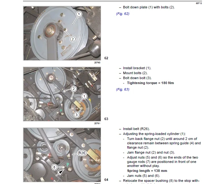
9 10 8 Removing the belt (1) 635
9 10 9 Installing the belt (1) 635
9 10 10Removing the belt (2) 636
9 10 11 Installing the belt (2) 638
9 10 12Removing the belt (3) 639
9 10 13Installing the belt (3) 640
9 10 14Removing the belt (4) 642
9 10 15Installing the belt (4) 644
9 10 16Removing the belt (5) 645
9 10 17Installing the belt (5) 647
9 10 18Removing belt (6) (without torque support) 648
9 10 19Installing belt (6) (without torque support) 649
9 10 20Removing belt (6) (with torque support) 650
9 10 21Installing belt (6) (with torque support) 651
9 10 22Removing the belt (7) 652
9 10 23Installing the belt (7) 655
9 10 24Removing the belt (8) 657
9 10 25Installing the belt (8) 658
9 10 26Removing the belt (9) 659
9 10 27Installing the belt (9) 662
9 10 28Removing the belt (10) 664
9 10 29Installing the belt (10) 665
9 10 30Removing the chain (11) 667
9 10 31Installing the chain (11) 668
9 10 32Removing the belt (12) 669
9 10 33Installing the belt (12) 670
9 10 34Removing the belt (13) 672
9 10 35Installing the belt (13) 673
9 10 36Removing the belt (14) 674
9 10 37Installing the belt (14) 675
9 10 38Removing the belt (15) 676
20
69704
9 10 39Installing the belt (15) 677
9 10 40Removing the belt (16) 678
9 10 41Installing the belt (16) 679
9 10 42Removing the belt (17) 680
9 10 43Installing the belt (17) 681
9 10 44Removing the belt (18) 683
9 10 45Installing the belt (18) 685
9 10 46Removing the belt (19) 686
9 10 47Installing the belt (19) 687
9 10 48Removing the belt (20) 689
9 10 49Installing the belt (20) 691
9 10 50Removing belt (21) (up to serial no ) 693
9 10 51Installing belt (21) (up to serial no ) 695
9 10 52Removing the belt (21) (from serial no ) 696
9 10 53Installing belt (21) (from serial no ) 698
9 10 54Removing the belt (23) 699
9 10 55Installing the belt (23) 700
9 10 56Removing the belt (24) 701
9 10 57Installing the belt (24) 702
9 10 58Removing the belt (25) 702
9 10 59Installing the belt (25) 704
9 10 60Removing the belt (26) 707
9 10 61Installing the belt (26) 709
9 10 62Removing the belt (40) 711
9 10 63Installing the belt (40) 712
9 10 64Removing the belt (41) 713
9 10 65Installing the belt (41) 714
9 10 66Removing the belt (42) 716
9 10 67Installing the belt (42) 717
9 10 68Removing the belt (46) 718
9 10 69Installing the belt (46) 719
9 10 70Removing belt (R47) 720
9 10 71Installing belt (R47) 721
9 10 72Adjusting belt (R47) 722
9 10 73Removing the belt (48) 723
9 10 74Installing the belt (48) 724
9 10 75Removing the belt (49) 725
9 10 76Installing the belt (49) 726
9 10 77Removing the belt (50) 727
9 10 78Installing the belt (50) 729
9 10 79Removing the belt (51) 730
9 10 80Installing the belt (51) 731
9 10 81Removing the belt (52) 732
9 10 82Installing the belt (52) 733
9 10 83Removing the belt (53) 735
9 10 84Installing the belt (53) 737
9 10 85Removing the belt (54) 738
21
69704
9 10 86Installing the belt (54) 739
9 10 87Removing the chain (55) 740
9 10 88Installing the chain (55) 741
9 10 89Removing the chain (56) 741
9 10 90Installing the chain (56) 742
9 10 91Removing the belt (57) 743
9 10 92Installing the belt (57) 744
9 10 93Removing and installing belts (58), (60) and (61) 745
9 10 94Removing chain (K62) 745
9 10 95Installing the chain (K62) 746
9 10 96Adjusting chain (K62) 746
9 10 97Removing belt (R63) 747
9 10 98Installing belt (R63) 747
9 10 99Adjusting belt (R63) 747
9 11 Cab / air conditioner 749
9 11 1 Cleaning the cab filters 749
9 11 2 Cleaning the units located in the cab roof 749
9 11 3 Cleaning the windscreen and the side windows 750
9 11 4 Cleaning the condenser 751
9 11 5 Checking the refrigerant level 751
9 11 6 Replacing the filter receiver drier 752
9 11 7 Required refrigerant quantity – refrigerant R 134 a 752
9 11 8 Oil for the compressor 752
9 11 9 Maintenance work before the harvest 752
9 11 10Putting the air conditioner into operation 753
9 12 Fire extinguisher 754
9 12 1 Checking the fire extinguisher 754
9 13 Compressed-air system (accessory) 755
9 13 1 Compressed-air system 755
9 13 2 Compressed-air connections 756
9 13 3 Compressed-air gun and woven hose 756
9 13 4 Draining the accumulator 757
9 13 5 Pressure controller 757
9 13 6 Checking the safety valve 758
9 14 Straw chopper with uni-spreader 759
9 14 1 Replacing the free-swinging knives for grain 759
9 14 2 Removing the straw guide plate (straw chopper with uni-spreader) 759
9 14 3 Installing the straw guide plate (straw chopper with uni-spreader) 760
9 14 4 Removing the straw guide plate (rice straw chopper with standard spreader) 760
9 14 5 Installing the straw guide plate (rice straw chopper with standard spreader) 762
9 14 6 Removing the free-swinging knives for grain 763
9 14 7 Bolting down the free-swinging knives for grain 764
9 14 8 Replacing the stationary knives 766
9 15 Rice straw chopper with standard spreader 767
9 15 1 Replacing the free-swinging knives for grain 767
9 15 2 Removing the straw guide plate (rice straw chopper with standard spreader) 767
9 15 3 Installing the straw guide plate (rice straw chopper with standard spreader) 769
9 15 4 Removing the free-swinging knives for grain 770
22
69704
9 15 5 Bolting down the free-swinging knives for grain 771
9 15 6 Replacing the stationary knives 773
9 16 Straw chopper with radial spreader 774
9 16 1 Replacing the free-swinging knives for grain 774
9 16 2 Removing the straw guide plate (straw chopper with radial spreader) 774
9 16 3 Installing the straw guide plate (straw chopper with radial spreader) 775
9 16 4 Removing the free-swinging knives for grain 776
9 16 5 Bolting down the free-swinging knives for grain 777
9 16 6 Replacing the stationary knives 779
9 17 Straw chopper with standard spreader 780
9 17 1 Replacing the free-swinging knives for grain 780
9 17 2 Removing the straw guide plate (straw chopper with standard spreader) 780
9 17 3 Installing the straw guide plate (straw chopper with standard spreader) 782
9 17 4 Removing the free-swinging knives for grain 783
9 17 5 Bolting down the free-swinging knives for grain 784
9 17 6 Replacing the stationary knives 786
9 18 Winter storage 787
9 18 1 Winter storage instructions for combines 787
10 Maintenance – Engine
10 1 Important maintenance instructions 789
10 1 1 Important maintenance instructions and safety rules 789
10 1 2 Cooling water and air intake hoses 789
10 1 3 Coolant 789
10 1 4 Belts 789
10 1 5 Cleaning the engine compartment and hazard areas 790
10 1 6 Alternator 790
10 1 7 Warranty on non genuine CATERPILLAR products 790
10 1 8 Approved engine oils 790
10 1 9 Engine oils with dry lubricant additives 790
10 2 Maintenance schedules 791
10 2 1 Maintenance schedule Mercedes-Benz OM 502 LA 791
10 2 2 CATERPILLAR C-12 maintenance schedule 793
10 2 3 Maintenance schedule CATERPILLAR C-13 795
10 3 Lubricants charts 797
10 3 1 Lubricants chart of Mercedes-Benz OM 502 LA engine 797
10 3 2 Lubricants chart of Mercedes-Benz OM 502 LA cooling system 797
10 3 3 Engine lubricants chart CATERPILLAR C13, C12 798
10 3 4 Cooling system lubricants chart CATERPILLAR C13, C12 799
10 4 Engine overview 800
10 4 1 Engine overview of Mercedes-Benz OM 502 LA 800
10 4 2 Engine overview CATERPILLAR C-13 801
10 4 3 Engine overview CATERPILLAR C-12 802
10 5 Fuel system / engine oil 803
10 5 1 Fuel system 803
10 5 2 Fuel tank 803
10 5 3 Fuel tank breather (from serial no ) 804
10 5 4 Additional fuel tank (LEXION 580, accessory) 804
23
69704
10 5 5 Shut-off tap for additional fuel tank (LEXION 580, accessory) 804
10 5 6 Replaceable filter – Additional fuel tank (LEXION 580, up to serial no ) 805
10 5 7 Replaceable filter – Additional fuel tank (LEXION 580 from serial no ) 805
10 5 8 Fuel shut-off tap 806
10 5 9 Water separator / fuel prefilter (standard equipment – small version) 806
10 5 10Water separator / Fuel pre-filter (accessory) 807
10 5 11Manual fuel pump with fuel sediment bowl (Mercedes-Benz OM 502 LA) 808
10 5 12Replacing the fuel filter element (Mercedes-Benz OM 502 LA) 808
10 5 13Replacing the fuel filter cartridge (CATERPILLAR C-13 / C-12) 809
10 5 14Bleeding the fuel system 810
10 5 15Engine oil level check 810
10 5 16Engine oil change 811
10 5 17Draining used oil 812
10 5 18Oil filter 813
10 5 19Topping up engine oil 814
10 6 Cooling system 815
10 6 1 Coolant 815
10 6 2 Draining coolant from the water radiator 815
10 6 3 Topping up coolant 816
10 6 4 Identify the coolant type 818
10 6 5 Coolant mixing ratio 819
10 6 6 Changing the coolant 819
10 6 7 Shut down the overheated engine 821
10 6 8 Rotary chaff screen 822
10 6 9 Cleaning the water cooler (rotary chaff screen) 823
10 6 10Cleaning the cooling unit (planar rotary chaff screen) 824
10 6 11Greasing the chain (K62) 827
10 6 12Installing the deflector (planar rotary chaff screen) 827
10 6 13Adjusting the nozzle (planar rotary chaff screen) 829
10 6 14Diesel engine fault 830
10 7 Dry-type air cleaner 832
10 7 1 Dry-type air cleaner in general 832
10 7 2 Warning device 833
10 7 3 Cleaning the air filter suction screen (up to serial no ) 834
10 7 4 Cleaning the air filter suction screen (from serial no ) 834
10 7 5 Cleaning the air filter with plastic housing 835
10 7 6 Cleaning the air filter with metal housing 837
10 7 7 Safety filter cartridge 839
10 7 8 Removing and installing safety cartridge (plastic housing) 840
10 7 9 Removing and installing safety cartridge (metal housing) 841
10 8 Alternator 842
10 8 1 Cleaning the alternator 842
10 9 Electrical system 843
10 9 1 Battery 843
10 9 2 Alternator 844
10 10Problem, cause and / or remedy 845
10 10 1Engine 845
24
69704
10 11Winter storage 847
10 11 1Engine winter storage 847
11 Lubrication chart
11 1 Lubrication points 848
11 1 1 Greasing cycles 848
11 1 2 Lubrication points – 10 h on the left 851
11 1 3 Lubrication points – 50 h on the left 852
11 1 4 Lubrication points – 50 h on the right 854
11 1 5 Lubrication points – 100 h on the left 856
11 1 6 Lubrication points – 100 h on the right 859
11 1 7 Lubrication points – 500 h on the left 861
11 1 8 Lubrication points – 500 h on the right 862
IMAGES PREVIEW OF THE MANUAL:
Need help? Contact: [email protected]
PLEASE NOTE:
- This is the SAME exact manual used by your dealers to fix your vehicle.
- The same can be yours in the next 2-3 mins as you will be directed to the download page immediately after paying for the manual.
- Any queries / doubts regarding your purchase, please feel free to contact [email protected]
S.V