CLAAS LEXION 600 – 510 Technical & Electric System Service Manual – PDF DOWNLOAD
Original price was: $80.00.$29.95Current price is: $29.95.
CLAAS LEXION 600 – 510 Technical & Electric System Service Manual – PDF DOWNLOAD
From serial number: 589 00018
586 00918
585 00358
584 02256
583 00868
Description
CLAAS LEXION 600 – 510 Technical & Electric System Service Manual – PDF DOWNLOAD
DESCRIPTION:
CLAAS LEXION 600 – 510 Technical & Electric System Service Manual – PDF DOWNLOAD
Description of function:
Starting
The engine controller module (A15) is activated via relay K51 by the ignition lock (S64). During the starting procedure, the engine controller module (A15) receives the speed signal from the sensor provided on the camshaft and starts the injection.
Engine monitoring
All sensors relevant for operation and monitoring of the engine are mounted on the engine wiring loom. Only the water level sensor is connected to the CLAAS wiring loom. The engine controller module (A15) transmits the signals for displaying the engine speed, coolant level and the coolant temperature to the CAB module (A10) via the CAN bus J1939. The CAN module (A10) converts this signal to the CLAAS CAN bus, thus allowing display on the terminal.
TABLE OF CONTENTS:
CLAAS LEXION 600 – 510 Technical & Electric System Service Manual – PDF DOWNLOAD
Technical Systems – Electric System LEXION 600 – 510, from serial number: 589 00018, 586 00918, 585 00358, 584 02256, 583 00868 1
Layout of electric circuit diagrams 3
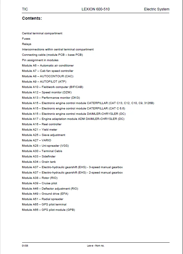
Contents 7
Central terminal compartment 11
Fuses 13
Relays 16
Interconnections within central terminal compartment 19
Connecting cable (module PCB – base PCB) 31
Pin assignment in modules 35
Module A6 – Automatic air conditioner 37
Module A7 – Cab fan speed controller 37
Module A8 – AUTOCONTOUR (CAC) 38
Module A9 – AUTOPILOT (ATP) 39
Module A10 – Fieldwork computer (BIF/CAB) 40
Module A12 – Speed monitor (DZW) 41
Module A13 – Performance monitor (DKG) 42
Module A15 – Electronic engine control module CATERPILLAR (CAT C13, C12, C10, C9, 3126B) 43
Module A15 – Electronic engine control module CATERPILLAR (CAT C 66) 43
Module A15 – Electronic engine control module DAIMLER-CHRYSLER (DC) 44
Module A17 – Engine adaptation module ADM DAIMLER-CHRYSLER (DC) 44
Module A16 – Reel controller 45
Module A21 – Yield meter 46
Module A25 – Sieve adjustment 47
Module A27 – VARIO 48
Module A28 – Uni-spreader (VGS) 49
Module A30 – Terminal Cebis 50
Module A33 – Sidefinder 51
Module A34 – Grain tank 52
Module A37 – Electro-hydraulic gearshift (EHS) – 3-speed manual gearbox 53
Module A37 – Electro-hydraulic gearshift (EHS) – 2-speed manual gearbox 53
Module A38 – Rotor (RIO) 54
Module A39 – Cruise pilot 54
Module A46 – Deflector adjustment (RIO) 56
Module A49 – Ground drive (EFA) 57
Module A51 – Radial spreader 58
Module A65 – GPS pilot terminal 59
Module A66 – GPS pilot module (GPB) 59
Circuit diagrams 01a – 50a 61
01a Main power supply, diesel engine electric starting motor 61
02a Starting the diesel engine, diesel engine electric starting motor – C13 ACERT, C9 ACERT (TIER III) 65
02b Starting the diesel engine, diesel engine electric starting motor – CAT C12, 3126B 69
02c Starting the diesel engine, diesel engine electric starting motor – CAT C66 73
02d Starting the diesel engine, diesel engine electric starting motor – DC 502 LA 77
03a Diesel engine cut-off system 81
04a Road travel activation, master valve (not with electro-hydraulic ground drive) 93
04b Road travel activation, master valve – with electro-hydraulic ground drive (EFA) 97
05a Terminal, keyboard, rotary switch, printer (not with electro-hydraulic ground drive) 101
05b Terminal, keyboard, rotary switch, printer – with electro-hydraulic ground drive (EFA) 105
06a CAN bus, module power supply, for diesel engine CATERPILLAR – C13, C12, C10, C9, 3126B 109
06b CAN bus, module power supply, for diesel engine CATERPILLAR – C66 117
06c CAN bus, module power supply, for diesel engine Daimler – Chrysler DC 502 LA 125
07a Threshing mechanism circuit 133
08a Concave adjustment / Threshing drum variable-speed drive 137
09a Rotor flap adjustment / Rotor variable-speed drive 143
10a Fan variable-speed drive 149
11a Sieve adjustment 153
12a Deflector adjustment 157
13a Straw and chaff spreader, uni-spreader 161
13b Straw and chaff spreader, radial spreader 167
14a Swinging the grain tank unloading tube 173
15a Grain tank unloading / Grain tank unloading aid 177
16a Rape cutting knife circuit 183
17a Front attachment drive, reverser drive, front attachment quick stop 189
18a Front attachment variable-speed drive 195
19a Straw chopper – Standard chopper for LEXION 570 – 510 199
19b Straw chopper – Radial spreader for LEXION 600 – 570 203
20a Front attachment raise/lower, cross levelling 209
21a Reel adjustment – Standard cutterbar, folding cutterbar, MaxFlex soybean header 215
21b Reel adjustment – VARIO cutterbar 221
21c Maize picker Conspeed – Folding the maize picker, snapping plate adjustment, down maize augers 227
21d Rake-up – Drive, rake-up crop guard adjustment 233
22a Reel variable-speed drive 239
23a Cutting table adjustment (Vario), folding the cutterbar 245
23b Cutting table adjustment – MaxFlex 251
24a AUTOCONTOUR (CAC) 257
25a Speed monitor 263
26a Machine monitor (not with electro-hydraulic ground drive) 269
26b Machine monitor – with electro-hydraulic ground drive (EFA) 275
27a Yield meter / Grainmeter 281
28a AUTOPILOT – Laser system 287
28b AUTOPILOT – Feeler system 295
28c AUTOPILOT – GPS-controlled steering 303
29a Performance monitor 309
30a Open / close grain tank (electric), grain tank full signal, warning beacon 313
30b Open / close grain tank (hydraulic), grain tank full signal, warning beacon 317
31a Front attachment dampening 321
32a All-wheel drive – overdrive, fuel tank (not with electro-hydraulic ground drive) 327
32b All-wheel drive – overdrive, fuel tank – with electro-hydraulic ground drive (EFA) 331
33a Cutterbar spring lock (only when front attachment cylinder is equipped with a spring) 335
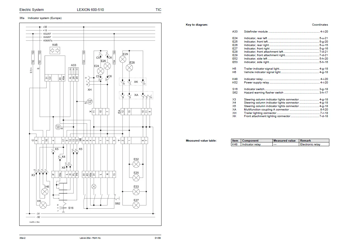
36a Indicator system (Europe) 339
36b Indicator system (USA) 345
37a Windscreen wiper, windscreen washer 351
38a Compressor-type air conditioner 355
38b Automatic air conditioner 359
39a Cab comfort equipment – operator’s seat 369
40a Additional sockets, fuse tester 373
42a Ground drive and brake control – with electro-hydraulic ground drive (EFA) 377
43a Electro-hydraulic ground drive (EFA), „CRUISE PILOT“ 381
44a Electro-hydraulic gearshift (EHS) – 3-speed manual gearbox 397
44b Electro-hydraulic gearshift (EHS) – 2-speed manual gearbox (not for LEXION Montana*) 403
45a Main lighting circuit, taillight, position light 409
46a Dipped headlights, full beam, dipped headlights changeover switch 415
47a Work lights I 419
48a Work lights II 423
49a Sieve, grain tank and returns lighting, reversing horn, brake light (not with electro-hydraulic ground drive) 427
49b Sieve, grain tank and returns lighting, reversing horn, brake light – with electro-hydraulic ground drive (EFA) 433
50a Instrument lighting, broadcast receiver, mirror adjustment 439
Component grid 444
Index447
A – C448
D – F449
G – L450
M – R451
S – Y452
0294 0591454
IMAGES PREVIEW OF THE MANUAL:
Questions? Email us: [email protected]
https://vimeo.com/676544765
CLAAS LEXION 600 – 510 TECHNICAL & ELECTRIC SYSTEM SERVICE MANUAL – PDF DOWNLOAD:
PLEASE NOTE:
- This is the SAME exact manual used by your dealers to fix your vehicle.
- The same can be yours in the next 2-3 mins as you will be directed to the download page immediately after paying for the manual.
- Any queries / doubts regarding your purchase, please feel free to contact [email protected]
S.M