CLAAS LEXION 600 – 510 Technical & Hydraulic System Service Manual – PDF DOWNLOAD
Original price was: $80.00.$27.95Current price is: $27.95.
CLAAS LEXION 600 – 510 Technical & Hydraulic System Service Manual – PDF DOWNLOAD
Description
CLAAS LEXION 600 – 510 Technical & Hydraulic System Service Manual – PDF DOWNLOAD
DESCRIPTION:
CLAAS LEXION 600 – 510 Technical & Hydraulic System Service Manual – PDF DOWNLOAD
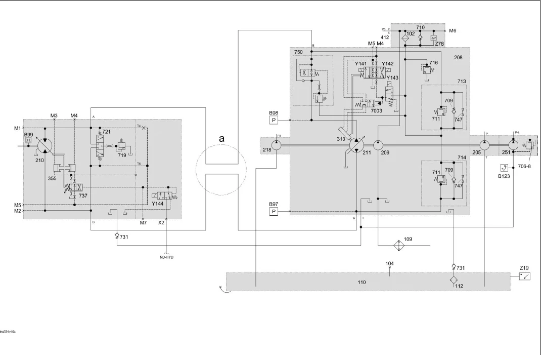
Description of function:
Steering actuation function
- Via the rotor (229) and the rotary disc valve (609), the volume flow is released to the piston or the piston rod side of the steering cylinder (323) as a function of sense of rotation and rotational speed of the steering wheel. Here, the displacing surface of the steering cylinder (323) is connected with the return line to the tank via the rotary disc valve (609).
- As soon as there is no more steering motion, leaf springs bring the inner and outer rotary discs (609) back to neutral position. Now both sides of the steering cylinder are shut off again and the connection from the pump (218) to the tank is re-established.
Emergency steering function
- When the steering system is not supplied any more externally by pump (218), the non-return valve (742) closes and thus ensures that no oil will escape from the steering system.
- When actuating the steering in one direction, the inner and outer rotary disc of the rotary disc valve (609) are twisted against each other correspondingly. Now the oil can be conveyed from one side of the steering cylinder (323) via non-return valve (728) to the other side through human power by driving the rotor (229).
- On machines with one steering cylinder (323), a reservoir in the return line to the tank compensates the volumetric difference between the piston and piston ring surface.
- When actuating the steering in one direction, the inner rotary disc (609) is twisted against the outer rotary disc (609) by up to 8°. During this process, the return line from the pump (218) to the tank is closed and the connection to the proportioning pump (229) is released.
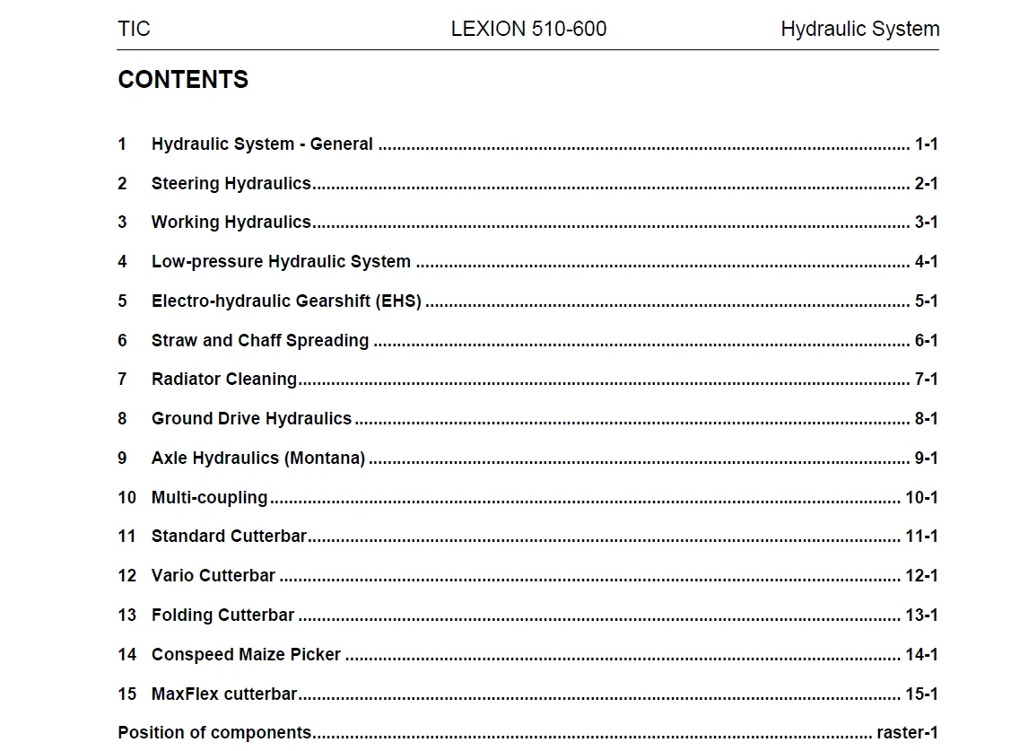
TABLE OF CONTENTS:
CLAAS LEXION 600 – 510 Technical & Hydraulic System Service Manual – PDF DOWNLOAD
Technical Systems – Hydraulic System LEXION 600 – 510 1
Contents 3
1 Hydraulic System – General 5
11 Hydraulic System – General 7
111 Oil Tank (entire hydraulic system) 8
112 Hydraulic Pumps 10
113 Hydraulic Motors 14
114 Valve Inserts 16
12 Overall Hydraulic System Circuit Diagram 19
121 Overall Hydraulic System Circuit Diagram of Rotor Machines LEXION 600 – Wheeled machine 21
122 Overall Hydraulic System Circuit Diagram of Rotor Machines LEXION 600 Terra Trac 23
123 Overall Hydraulic System Circuit Diagram of Rotor Machines LEXION 580 up to serial no 586 00336 25
124 Overall Hydraulic System Circuit Diagram of Rotor Machines LEXION 580 from serial no 586 00337 27
125 Overall Hydraulic System Circuit Diagram of Rotor Machines LEXION 570 with standard straw chopper, up to serial no 585 00162 29
126 Overall Hydraulic System Circuit Diagram of Rotor Machines LEXION 570 with standard straw chopper, from serial no 585 00163 31
127 Overall Hydraulic System Circuit Diagram of Rotor Machines LEXION 570 with radial spreader, up to serial no 585 00162 33
128 Overall Hydraulic System Circuit Diagram of Rotor Machines LEXION 570 with radial spreader, from serial no 585 00163 35
129 Overall Hydraulic System Circuit Diagram of Straw Walker Machines LEXION 560-510 up to serial no 584 00895, 583 00298 37
1210 Overall hydraulic system circuit diagram of straw walker machines LEXION 560-510 from serial no 584 00896, 583 00299 39
2 Steering Hydraulics 49
21 Steering Hydraulics Circuit Diagrams 51
211 Steering Hydraulics Circuit Diagram with AUTOPILOT for concave adjustment with filling valve – LEXION 600 / 580 / 570 53
212 Steering Hydraulics Circuit Diagram with AUTOPILOT for concave adjustment without filling valve – LEXION 560 – 510 57
213 Steering Hydraulics Circuit Diagram without AUTOPILOT 61
22 Steering 65
221 Function of Steering 66
222 Function of Steering – double-stage Orbitrol units 72
23 AUTOPILOT 75
231 AUTOPILOT Right/Left Function 76
3 Working Hydraulics 0
31 Working Hydraulics Circuit Diagram 85
311 Working Hydraulics Circuit Diagram of Rotor Machines LEXION 600 – Wheeled machine 87
312 Working Hydraulics Circuit Diagram of Rotor Machines LEXION 600 Terra Trac 89
313 Working Hydraulics Circuit Diagram of Rotor Machines LEXION 580 up to serial no 586 00336 91
314 Working Hydraulics Circuit Diagram of Rotor Machines LEXION 580 from serial no 586 00337 93
315 Working Hydraulics Circuit Diagram of Rotor Machines LEXION 570 with standard straw chopper, up to serial no 585 00162 95
316 Working Hydraulics Circuit Diagram of Rotor Machines LEXION 570 with standard straw chopper, from serial no 585 00163 97
317 Working Hydraulics Circuit Diagram of Rotor Machines LEXION 570 with radial spreader, up to serial no 585 00162 99
318 Working Hydraulics Circuit Diagram of Rotor Machines LEXION 570 with radial spreader, from serial no 585 00163101
319 Working Hydraulics Circuit Diagram of Straw Walker Machines LEXION 560-510 up to serial no 584 00895, 583 00298103
3110 Working Hydraulics Circuit Diagram of Straw Walker Machines LEXION 560-510 from serial no 584 00896, 583 00299105
32 Front attachment raise/lower main solenoid valve111
321 Main Valve 112
33 Concave Adjustment123
331 Concave Adjustment – LEXION 600 / 580 / 570 Hydro-Pneumatic Overload System with Filling Valve 124
332 Concave Adjustment – LEXION 560 – 510 Hydraulic Overload System without Filling Valve 130
34 Threshing Drum Speed Control135
341 Threshing Drum Speed Control 136
35 Uni-spreader / Radial spreader / Swing Swathing Flap141
351 Swing Uni-spreader 142
352 Swing Radial spreader 146
353 Swing Swathing Flap 150
36 Swing Grain Tank Unloading Tube155
361 Swing Grain Tank Unloading Tube 156
37 Rotor Speed Control161
371 Rotor Speed Control 162
38 Front Attachment Quick Stop167
381 Front Attachment Quick Stop 168
39 Cutterbar Spring Lock173
391 Cutterbar Spring Lock 174
310 Feed Rake Conveyor / Front Attachment Speed Controller179
3101 Feed Rake Conveyor / Front Attachment Speed Controller 180
311 Open / close grain tank (hydraulic) Grain Tank Unloading Aid185
3111 Open / close grain tank (hydraulic) 186
3112 Grain Tank Unloading Aid 190
312 AUTO-CONTOUR (CAC)195
3121 AUTO-CONTOUR (CAC) – Front attachment cross levelling – LEXION 580 – 510 up to serial no 586 00336, 585 00162, 584 00895, 583 00298 197
3122 AUTO-CONTOUR (CAC) – Front attachment cross levelling – LEXION 600 – 510 from serial no 589 00011, 586 00337, 585 00163, 584 00896, 583 00299 205
313 Reverse Front Attachment213
3131 Reverse Front Attachment with AUTO-CONTOUR LEXION 600-510 215
3132 Reverse Front Attachment without AUTO-CONTOUR 221
314 Front Attachment Dampening227
3141 Front attachment dampening – on front attachment cylinders with a spring 228
3142 Front attachment dampening – on front attachment cylinders with a spring 230
315 Half-tracks Tension233
3151 Half tracks tension 234
3152 Half tracks tension 236
316 Cutting frame adjustment Montana239
317 Cutting angle adjustment Montana241
318 Service brake (filling the brake accumulator)243
3181 Filling the brake accumulator – LEXION 600 Terra Trac, LEXION Montana 244
4 Low-pressure Hydraulic System249
41 Low-pressure Hydraulic System LEXION 600-510251
411 Low-pressure hydraulic system circuit diagram LEXION 600 (Wheeled machine) 253
412 Low-pressure hydraulic system circuit diagram LEXION 600 Terra Trac 257
413 Low-pressure Hydraulic System Diagram LEXION 580-510 261
414 Pressure Relief Valve Of Low-pressure Hydraulic System 264
415 Low-pressure hydraulic system solenoid valves 266
416 Hydraulic Cylinder of Low-pressure Hydraulic System 272
417 3-D Cleaning System 288
418 Grain Tank Unloading Chain Lubrication 290
5 Electro-hydraulic Gearshift (EHS)293
51 Electro-hydraulic Gearshift (EHS) Circuit Diagram LEXION 580-510 295
52 Electro-hydraulic gearshift (EHS) LEXION 600 301
6 Straw and Chaff Spreading305
61 Straw and Chaff Spreader307
611 Straw and Chaff Spreader Circuit Diagram 309
612 Straw and Chaff Spreader Drive 312
62 Uni-spreader315
621 Uni-spreader (VGS) Circuit Diagram 317
622 Uni-spreader (VGS) Drive 320
63 Radial spreader327
631 Radial spreader circuit diagram 329
632 Radial spreader working/transport position 332
633 Radial spreader transport position 338
634 Radial spreader – deflector drive 342
7 Radiator Cleaning347
71 Rotary Chaff Screen349
711 Rotary Chaff Screen Circuit Diagram 351
712 Rotary Chaff Screen Drive 354
72 Planar rotary chaff screen cleaning357
721 Planar rotary chaff screen cleaning circuit diagram 359
722 Planar rotary chaff screen cleaning drive 362
8 Ground Drive Hydraulics365
81 Hydrostatic Ground Drive – Mechanical Control367
811 Hydrostatic Ground Drive Circuit Diagram – Mechanical Control up to serial no 586 00336, 585 00162, 584 00895, 583 00298, 582 00051, 581 00037, 580 00028 369
812 Hydrostatic Ground Drive Circuit Diagram – Mechanical Control from serial no 586 00337, 585 00163, 584 00896, 583 00299, 582 00052, 581 00038, 580 00029 371
813 Pump Unit 376
814 Motor Unit 382
815 Ground Drive Hydraulic Motor Brake Restrictor (HBM) Control – up to serial no 586 00336, 585 00162, 584 00895, 583 00298, 582 00051, 581 00037, 580 00028 384
816 Ground Drive Hydraulic Motor Brake Restrictor Control – Integrated brake function from serial no 586 00337, 585 00163, 584 00896, 583 00299, 582 00052, 581 00038, 580 00029 386
82 Hydrostatic Ground Drive – Electronic Control (EFA)389
821 Circuit diagram of hydrostatic ground drive – Electronic control (EFA) 392
822 Circuit diagram of hydrostatic ground drive – Electronic control (EFA) 396
823 Ground drive variable-displacement pump with valve unit 398
824 Hydraulic motor speed adjustment sensor 404
83 4-Trac Drive (All-wheel drive)407
831 MUD HOG valve unit 408
832 POCLAIN radial piston motor 410
833 4-Trac Overdrive 412
9 Axle Hydraulics (Montana)415
10 Multi-coupling417
11 Standard Cutterbar421
111 Standard Cutterbar Circuit Diagram 423
112 Vertical Reel Adjustment (Standard Cutterbar) 426
113 Horizontal Reel Adjustment (Standard Cutterbar) 430
114 Reel Rpm Adjustment (Standard Cutterbar) 434
115 Rape Knife Drive (Standard Cutterbar) 438
12 Vario Cutterbar441
121 Vario Cutterbar Circuit Diagram 443
122 Vertical Reel Adjustment (Vario Cutterbar) 446
123 Horizontal Reel Adjustment (Vario Cutterbar) 450
124 Reel Rpm Adjustment (Vario Cutterbar) 454
125 Cutting Table Adjustment (Vario Cutterbar) 458
126 Rape Knife Drive (Vario Cutterbar) 462
13 Folding Cutterbar465
131 Folding Cutterbar Circuit Diagram 467
132 Vertical Reel Adjustment (Folding Cutterbar) 470
133 Horizontal Reel Adjustment (Folding Cutterbar) 474
134 Reel Rpm Adjustment (Folding Cutterbar) 478
135 Folding the cutterbar 482
14 Conspeed Maize Picker487
141 Conspeed Maize Picker Circuit Diagram / 6-row 489
142 Conspeed Maize Picker Circuit Diagram / 8-row 493
143 Folding the Snapping Units / Adjusting the Snapping Plates – Conspeed Maize Picker 496
15 MaxFlex cutterbar499
151 MaxFlex Cutterbar Circuit Diagram 501
152 Vertical Reel Adjustment (MaxFlex Cutterbar) 504
153 Horizontal Reel Adjustment (MaxFlex Cutterbar) 508
154 Cutterbar lock (MaxFlex cutterbar) 512
Position of components517
Component grid566
Index569
A – F571
G – P572
R – W573
0299 6962 576
IMAGES PREVIEW OF THE MANUAL:
Contact us: [email protected]
https://vimeo.com/676563006
CLAAS LEXION 600 – 510 TECHNICAL & HYDRAULIC SYSTEM SERVICE MANUAL – PDF DOWNLOAD:
PLEASE NOTE:
- This is not a physical manual but a digital manual – meaning no physical copy will be couriered to you. The manual can be yours in the next 2 mins as once you make the payment, you will be directed to the download page IMMEDIATELY.
- This is the same manual used by the dealers inorder to diagnose your vehicle of its faults.
- Require some other service manual or have any queries: please WRITE to us at [email protected]
S.M