Claas Liebherr D934 A7-04 D936 A7-04 D944 A7-04 D946 A7-04 Diesel engine Repair Manual – PDF DOWNLOAD
Original price was: $89.00.$25.95Current price is: $25.95.
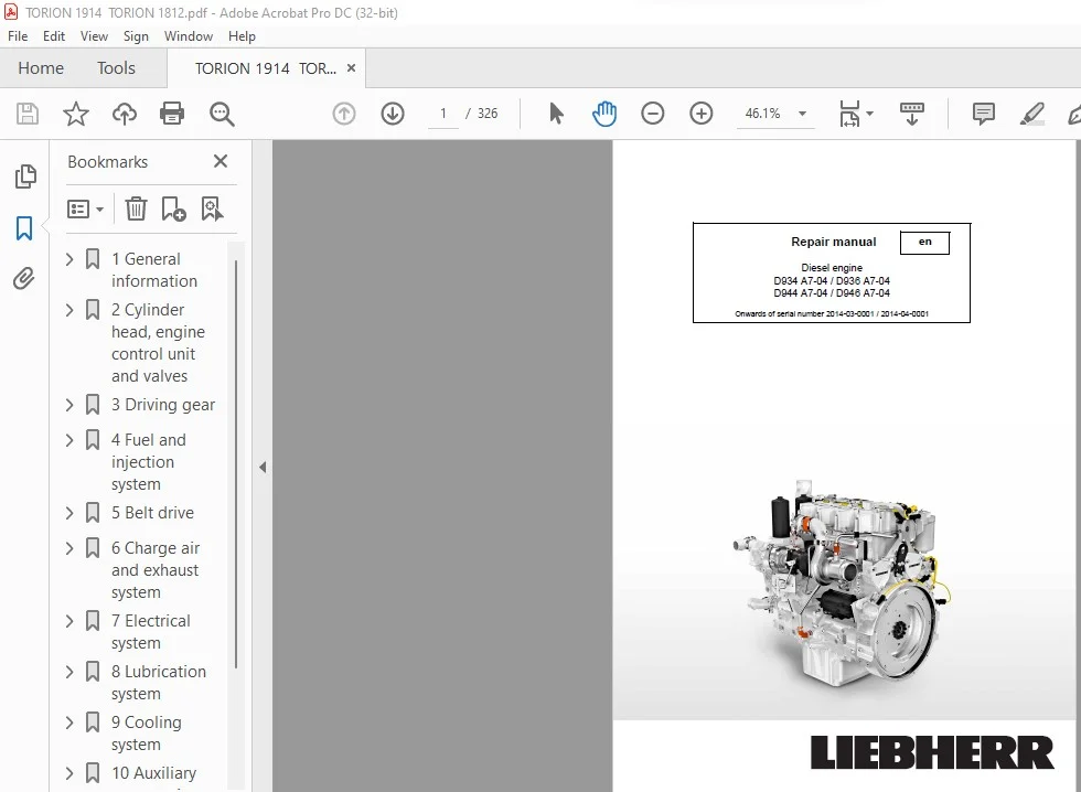
Claas Liebherr D934 A7-04 D936 A7-04 D944 A7-04 D946 A7-04 Diesel engine Repair Manual – PDF DOWNLOAD
serial number 2014-03-0001 / 2014-04-0001
Description
Claas Liebherr D934 A7-04 D936 A7-04 D944 A7-04 D946 A7-04 Diesel engine Repair Manual – PDF DOWNLOAD
DESCRIPTION:
Claas Liebherr D934 A7-04 D936 A7-04 D944 A7-04 D946 A7-04 Diesel engine Repair Manual – PDF DOWNLOAD
serial number 2014-03-0001 / 2014-04-0001
Preface
Target group
These repair instructions are written for fitters and workshop personnel of LIEBHERR dealers and LIEBHERR branches, whose task is to ensure that the diesel engines are ready to operate.
Contents
These repair instructions provide you with technical documents to hand, which you can use for removal and installation, dismantling and assembling, setting tasks and technical data for Liebherr diesel engines. The operating instructions D934 A7-04 / D936 A7-04 / D944 A7-04 / D946 A7-04 are part of these repair instructions and provide descriptions for maintenance and care
Safety instructions
The accident prevention regulations and all generally recognised safety and occupational health regulations are to be observed during all maintenance and repair work on Liebherr diesel engines. Observe the national regulations in the country and place of use if necessary. Furthermore, the safety instructions for diesel engines provided in the “Safety instructions” chapter must be observed.
General information
Safety instructions
- Regularly check that personnel are conscious of safety and hazards involved in their work while considering the accident prevention regulations and the generally recognised safety and occupational health regulations, as well as the repair instructions.
- Ensure that the personnel wear safe work clothing. Forbid the wearing of rings, wristwatches, ties, scarves, open jackets, dresses that are not form-fitting, etc. A risk of injury exists, e.g. by getting caught or pulled in.
- A prerequisite for a safe repair is a proper and complete basic tool, as well as the required devices and special tools.
- Use only clean and undamaged tools. Damaged tools must not be re-used; they must be replaced in good time. • Cleanliness and order contribute to safety at the workplace.
- Make preparations for potential emergencies that could arise. Keep fire extinguishers and first aid kits at hand. Keep emergency telephone numbers at hand.
- Ensure that the work area is sufficiently lit.
- Repair work may only be carried out when the diesel engine is switched off. Ensure that unauthorised people cannot start the diesel engine inadvertently.
TABLE OF CONTENTS:
Claas Liebherr D934 A7-04 D936 A7-04 D944 A7-04 D946 A7-04 Diesel engine Repair Manual – PDF DOWNLOAD
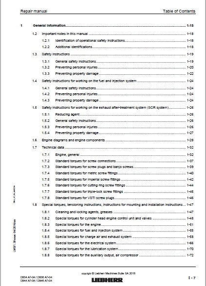
1 General information 1-13
12 Important notes in this manual 1-18
121 Identification of operational safety instructions 1-18
122 Additional identifications 1-18
13 Safety instructions 1-19
131 General safety instructions 1-19
132 Preventing personal injuries 1-20
133 Preventing property damage 1-22
14 Safety instructions for working on the fuel and injection system 1-24
141 General safety instructions 1-24
142 Preventing personal injuries 1-24
143 Preventing property damage 1-24
15 Safety instructions for working on the exhaust after-treatment system (SCR system) 1-26
151 Reducing agent 1-26
152 General safety instructions 1-26
153 Preventing personal injuries 1-26
154 Preventing property damage 1-27
16 Engine diagrams and engine components 1-28
17 Technical data 1-32
171 Engine, general 1-32
172 Standard torques for screw connections 1-37
173 Standard torques for screw plugs and banjo screws 1-39
174 Standard torques for metric screw fittings 1-40
175 Standard torques for imperial screw fittings 1-42
176 Standard torques for cutting ring screw fittings 1-44
177 Standard torques for triple-lock screw fittings 1-45
178 Standard torques for VSTI screw plugs 1-46
18 Special torques, tensioning instructions, instructions for mounting and installation instructions 1-47
181 Cleaning and locking agents, greases 1-47
182 Special torques for cylinder head engine control unit and valves 1-48
183 Special torques for the engine 1-51
184 Special torques for fuel and injection system 1-55
185 Special torques for charge air and exhaust system 1-58
186 Special torques for the electrical system 1-66
187 Special torques for the lubrication system 1-70
188 Special torques for the auxiliary output, air compressor 1-72
Table of Contents
i – 8
Repair manual
D934 A7-04 / D936 A7-04
D944 A7-04 / D946 A7-04
LMB/13/Issue: 04/2016/en D9xx_A7_04_deIVZfm
copyright © Liebherr Machines Bulle SA 2015
19 Fuel diagram 1-74
110 Lubricating oil diagram 1-75
111 Coolant diagram 1-76
1111 Coolant diagram, general overview 1-76
1112 Coolant circuit, engine 1-78
112 Assigning the channels in the crankcase and the cylinder head 1-81
113 Transport device and fastening parts 1-82
1131 Removing and installing the transport device and fastening parts 1-83
114 Tools 1-84
1141 Special tools 1-84
2 Cylinder head, engine control unit and valves 2-107
21 Removing and installing the cylinder head cover 2-108
22 Removing and installing the rocker arm bracket and push rods 2-109
23 Removing and installing the valve bridge (engines with and without ABS) 2-111
24 Removing and installing the cylinder head 2-112
25 Removing and installing the injector sleeve 2-115
26 Removing and installing the valve stem seal, valve springs, valves 2-117
261 Remove 2-118
262 Installing 2-119
263 Removing and installing the valve stem seal without removing the cylinder head 2-120
27 Removing and installing the roller tappet (valve controller) 2-122
28 Removing and installing the camshaft 2-123
281 Remove 2-124
282 Installing 2-125
3 Driving gear 3-127
31 Removing and installing the piston with crank and piston rings 3-129
311 Overview 3-129
312 A: Removing and installing the piston with crank from the engine 3-130
313 B: Removing and installing the piston rings 3-136
314 C: Removing and installing the pistons 3-138
32 Removing and installing the cylinder liner 3-139
321 Checking the cylinder liners’ projection 3-141
33 Removing and installing the crankshaft attachments 3-143
34 Removing and installing the front crankshaft seal 3-145
Repair manual
D934 A7-04 / D936 A7-04
D944 A7-04 / D946 A7-04
i – 9
Table of Contents
LMB/13/Issue: 04/2016/en D9xx_A7_04_deIVZfm copyright ©
Liebherr Machines Bulle SA 2015
341 General instructions 3-146
342 Remove 3-146
343 Installing 3-147
35 Removing and installing the unit carrier 3-150
36 Removing and installing the flywheel 3-153
361 Remove 3-156
362 Installing 3-158
363 Removing and installing the starting gear ring 3-160
37 Removing and installing the rear crankshaft seal 3-162
371 General instructions 3-163
372 Remove 3-163
373 Installing 3-164
38 Removing and installing the flywheel housing 3-167
39 Removing and installing the top right intermediate wheel 3-169
310 Removing and installing the top middle intermediate wheel 3-170
311 Removing and installing the crankshaft 3-171
3111 Remove 3-174
3112 Installing 3-177
4 Fuel and injection system 4-181
41 Removing and installing the fuel lines 4-182
42 Removing and installing the injection lines 4-184
421 Removing fuel lines 4-186
422 Installing fuel lines 4-187
43 Removing and installing the pressure pipe branch and injector 4-190
431 Removing the pressure pipe branch and injector 4-192
432 Installing the pressure pipe branch and injector 4-193
44 Removing and installing the fuel fine filter with console 4-196
441 Installing and filling the fuel fine filter 4-197
45 Removing and installing the fuel high pressure pump 4-199
451 Removing and installing the fuel pre-feed pump 4-202
452 Removing and installing the suction throttle valve 4-203
46 Removing and installing the fuel high pressure pump drive 4-204
5 Belt drive 5-205
51 Overview of belt drives 5-206
Table of Contents
i – 10
Repair manual
D934 A7-04 / D936 A7-04
D944 A7-04 / D946 A7-04
LMB/13/Issue: 04/2016/en D9xx_A7_04_deIVZfm
copyright © Liebherr Machines Bulle SA 2015
52 Removing and installing the belt drive cover 5-207
53 Removing and installing the V-ribbed belt tensioning device 5-208
54 Removing and installing the V-ribbed belt deflection roller 5-209
55 Removing and installing belt drive II (air conditioning compressor variant II) 5-210
56 Removing and installing belt drive III (fan drive) 5-211
6 Charge air and exhaust system 6-213
61 Removing and installing the air intake pipe 6-215
62 Removing and installing the air intake attachment 6-216
63 Removing and installing the clock valve 6-217
64 Removing and installing the connecting line (turbocharger – charge air cooler) 6-218
641 Connecting line (turbocharger – charge air cooler) variant 1 6-218
642 Connecting line (turbocharger – charge air cooler) variant 2 6-219
643 Connecting line (turbocharger – charge air cooler) variant 3 6-220
65 Removing and installing the heat protection plate 6-221
66 Removing and installing the exhaust pipe 6-222
661 Dismantling and assembling the 6-cylinder exhaust pipe 6-224
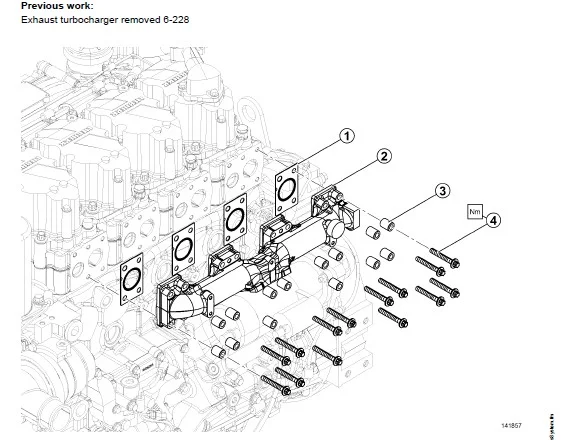
67 Removing and installing the exhaust branch 6-225
68 Removing and installing the intake branch 6-227
69 Removing and installing the turbocharger 6-228
610 SCR exhaust after-treatment system 6-231
6101 SCR functional overview 6-231
6102 SCR module 6-233
6103 Reducing agent pump 6-235
6104 Heating system for reducing agent lines 6-239
6105 Air compressor 6-240
6106 Reducing agent extraction module 6-242
6107 Mixing section, installing the injector and the high temperature sensor in the mixing
section 6-243
6108 Sensor section 6-246
6109 Removing and installing sensors 6-247
61010 WABCO water valve 6-250
611 Troubleshooting in SCR system 6-252
7 Electrical system 7-253
71 Removing and installing the heating flange 7-254
72 Removing and installing the alternator 7-256
Repair manual
D934 A7-04 / D936 A7-04
D944 A7-04 / D946 A7-04
i – 11
Table of Contents
LMB/13/Issue: 04/2016/en D9xx_A7_04_deIVZfm copyright ©
Liebherr Machines Bulle SA 2015
73 Removing and installing the starter 7-258
74 Removing and installing sensors 7-260
741 Instructions for mounting sensors 7-261
75 Removing and installing the engine control unit 7-262
751 Instructions for dismounting the engine control unit 7-263
752 Instructions for mounting the engine control unit 7-263
76 Replacing the cable harness 7-264
761 Preparation 7-264
762 Removing the cable harness 7-264
763 Installing the cable harness 7-265
8 Lubrication system 8-269
81 Replacing the oil filter 8-270
82 Removing and installing the crankcase ventilation 8-271
83 Removing and installing the oil return line (crankcase ventilation) 8-273
84 Removing and installing the oil dipstick and guiding pipe 8-274
85 Removing and installing the oil filler neck 8-275
86 Removing and installing the single-piece oil pan 8-276
87 Removing and installing the connecting piece (oil pan – crankcase) 8-280
88 Removing and installing the oil cooler housing with oil cooler 8-281
881 Dismantling and assembling the oil cooler housing with oil cooler 8-283
882 Removing and installing the cold start valve from/in the oil cooler housing 8-285
89 Removing and installing the oil pressure pump 8-287
810 Removing and installing the oil extraction pump (D936, D946) 8-289
8101 Removing and installing the suction and feed lines for the oil extraction pump (D 936, D
946) 8-290
811 Removing and installing the locking pieces for the oil extraction pump (D 936, D 946) 8-291
812 Removing and installing the piston cooling injector 8-292
813 Removing and installing the end control valve 8-294
9 Cooling system 9-295
91 Removing and installing the coolant ventilation line 9-296
92 Removing and installing the coolant pump 9-297
93 Removing and installing the coolant manifold 9-298
94 Removing and installing the thermostat housing and the thermostat 9-299
10 Auxiliary output, air compressor and air conditioning compressor 10-301
4 – 12
Repair manual
D934 A7-04 / D936 A7-04
D944 A7-04 / D946 A7-04
LMB/13/Issue: 04/2016/en D9xx_A7_04_deIVZfm
copyright © Liebherr Machines Bulle SA 2015
101 Overview of auxiliary outputs 10-302
102 Removing and installing auxiliary output 1 10-303
103 Removing and installing auxiliary output 2 10-305
104 Removing and installing auxiliary output 3 10-307
105 Removing and installing auxiliary output 4 10-308
106 Removing and installing the air compressor 10-310
107 Removing and installing the switchable auxiliary output on the flywheel housing 10-312
1071 Remove 10-313
1072 Installing 10-313
108 Dismantling the switchable auxiliary output for the spool repair kit 10-314
109 Dismantling and assembling the switchable auxiliary output bearing housing 10-319
1010 Installing and removing the air conditioning compressor, variant 1 10-321
1011 Installing and removing the air conditioning compressor, variant 2 10-322
11 Appendix 11-323
111 Symbols in this manual 11-324
112 Abbreviations used 11-325
IMAGES PREVIEW OF THE MANUAL:
CLAAS LIEBHERR D934 A7-04 D936 A7-04 D944 A7-04 D946 A7-04 DIESEL ENGINE REPAIR MANUAL – PDF DOWNLOAD:
PLEASE NOTE:
- This is the SAME MANUAL used by the dealerships to diagnose your vehicle
- No waiting for couriers / posts as this is a PDF manual and you can download it within 2 minutes time once you make the payment.
- Your payment is all safe and the delivery of the manual is INSTANT – You will be taken to the DOWNLOAD PAGE.
- So have no hesitations whatsoever and write to us about any queries you may have : heydownloadss @gmail.com