CLAAS MEDION 340 MEDION 330 MEDION 320 MEDION 310 Operator’s Manual- PDF DOWNLOAD
Original price was: $78.00.$24.95Current price is: $24.95.
CLAAS MEDION 340 MEDION 330 MEDION 320 MEDION 310 Operator’s Manual- PDF DOWNLOAD
Description
CLAAS MEDION 340 MEDION 330 MEDION 320 MEDION 310 Operator’s Manual- PDF DOWNLOAD
DESCRIPTION:
CLAAS MEDION 340 MEDION 330 MEDION 320 MEDION 310 Operator’s Manual- PDF DOWNLOAD
INTRODUCTION
- This Operator’s Manual is for the MEDION 340, MEDION 330, MEDION 320 and MEDION 310 combine harvester and is primarily intended for the machine operator to provide information on the use, the settings and the operation of the machine.
- In general, texts and pictures apply to all machine models covered by this manual. The information given applies equally, except where reference is made to a particular model in captions to the pictures or in the main text. Operation and maintenance of important accessories is also covered by this manual.
- Please read the instructions which apply to the appropriate accessories on your machine. Provided all instructions regarding maintenance and care of your machine are followed, you can count on many years of reliable service. Please have your authorised CLAAS dealer carry out the recommended regular inspections.
- The neglecting of regular maintenance and proper machine operation lead to reduced performance and loss of time. If proper operation and careful maintenance is ensured, your combine harvester, which incorporates latest harvesting technology, will render you excellent service
General information
ROAD TRAFFIC REGULATIONS
- Aside from a driving licence, the machine operator must always carry a photocopy of the general operating approval of the federal motor vehicle department, a hazard warning triangle and, for machines with a total permissible load over 4 metric tons, at least one wheel chock when driving the combine harvester.
- When driving on public roads with the combine harvester comply with all the requirements stated under letter C in the copy of the vehicle type approval registration (§ 18 Section 5 StVZO) issued by the Kraftfahrt-Bundesamt (the Federal Motor Vehicle Executive).
- On machines with excess width (width over the tyres), a vehicle type approval registration for individual vehicles (single expert opinion) and a special approval in accordance with § 70, Section 1, clauses 1 and 2 of the StVZO must be carried instead of the General Operating Permit. Furthermore, all the requirements stated in the vehicle type approval registration for individual vehicles and in the special approval must be observed.
- The issue of a special approval differs from country to country. The excess width must be marked in accordance with the regulations for the marking of road vehicles with excess width. (two marker boards at the front and back, protective bar, two amber flashing warning beacons.) If any part(s) of the combine harvester is/are subsequently modified whose condition is/are prescribed or the operation of which (after being modified) could represent a hazard to other road users, then the vehicle type approval registration shall no longer be valid and application must be made for a new vehicle type approval registration.
- In this case the machine must be presented to the motor vehicle safety inspection authority responsible (TÜV) in order to obtain an expert opinion certificate (§ 19 section 2 StVZO). If you are in any doubt as to whether this situation applies in your case, please contact us as manufacturers.
- If a transport vehicle for front end attachments is towed behind the combine harvester then the cable for the lighting system must be connected and the good condition of the lighting system assured. If the combine is equipped with a maize picker head or folding cutterbar, the regulations and requirements of the machine’s General Operating Permit must be observed, in particular the requirements concerning ballast weights and tyres
Registration
- As a self propelled working machine with a maximum speed of up to 20 km/h, the combine is not subject to registration and does not need to have licence plates fitted.
- The machine must be clearly and indelibly marked on the left-hand side with the Christian name and surname of the owner and his address.
- The towing of trailers in the trailer hitch when driving on public roads is not permitted. Road traffic regulations may vary between countries.
- In case of discrepancies between the instructions provided by the manufacturer and the traffic regulations of the relevant countries, the traffic regulations of the countries concerned apply.
TABLE OF CONTENTS:
CLAAS MEDION 340 MEDION 330 MEDION 320 MEDION 310 Operator’s Manual- PDF DOWNLOAD
1 Introduction
Introduction 111
2 Contents
Contents 211
3 General information
Road traffic regulations 311
Important note 321
Identification plate / Serial number 331
Identification plate 332
Machine serial number 332
Engine serial no PERKINS 1006-6 TA 332
Engine serial number
DAIMLER CHRYSLER OM 906 LA 333
Cutterbar identification plate 333
Straw chopper 333
Cab serial number 333
4 Safety Rules
Safety Regulations 411
Cylinder safety lock 414
Fire extinguisher 414
Battery isolating switch 415
Wheel chock (not for all countries) 415
Apply a wheel chock 415
Safety decals with pictorials 421
5 Specifications
CLAAS MEDION 340 511
CLAAS MEDION 330 / 320 / 310 521
Safety features 531
Front attachments – weights and dimensions 541
Sectional view of machine 551
Description and function 552
Cutterbar 552
Threshing mechanism 553
Straw walkers 553
Cleaning unit 553
Disawning 553
Basic rules for combining 554
6 Prior to operation
Carry out prior to initial operation 611
Cab 621
Cab with automatic air conditioner 621
Automatic air conditioner 622
Operating and display elements 622
Putting the automatic air conditioner into operation 623
Setting the cab temperature 624
Manually setting the evaporator blower speed 624
Activating ECON operating mode 625
Deactivating ECON operating mode 625
REHEAT operation (Dehumidify cab windows) 626
Displaying the outside temperature 627
Changing the temperature display to °Fahrenheit 627
Floor heating 627
Display of malfunction:
error in thermometer F0 (cab, blue) 628
Display of malfunction:
error in thermometer F1 (exhaust, yellow) 628
Display of malfunction:
error in thermometer F2 (outside, red) 628
Cab with air conditioner 629
Cab with fan 6210
Cab with fan and air conditioner 6210
Cab with fan and heater 6212
Floor heating 6212
Reheat system
(Dehumidify cab windows) 6212
Malfunction, possible cause or remedy –
air conditioner 6213
Opening and closing the cab roof 6215
Opening the cab roof 6215
Closing the cab roof 6215
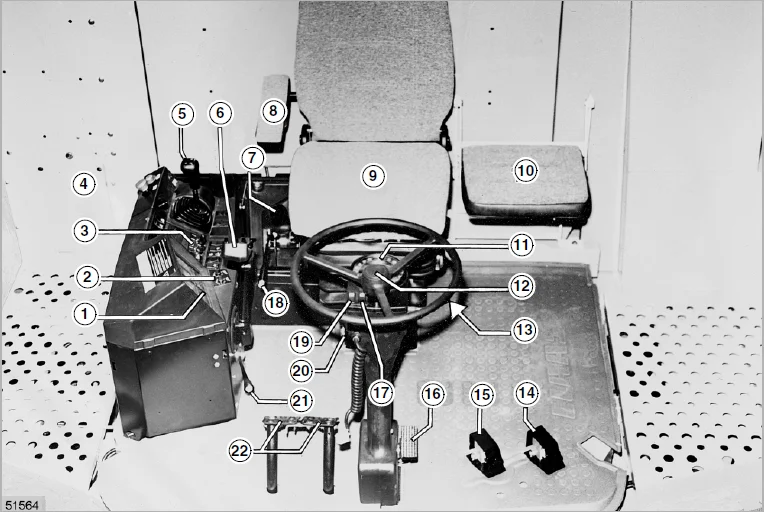
Operator’s platform 631
Steering column 632
Ignition switch 632
Vehicle information unit 633
Function of vehicle information unit 634
Operations display screen 635
Function of operations display screen 636
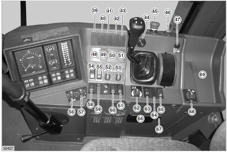
Switch console (up to serial no ) 637
Switch console (from serial no ) 638
Multifunction lever (up to serial no ) 639
Multifunction lever (from serial no ) 639
Central terminal compartment 6310
Plug-in type module (P) CLAAS Autopilot 6310
Positioning the cutterbar / maize picker head
for road travel 6311
Steering column adjustment 6311
Operator’s seat “air suspension” (option) 6312
Height adjustment 6312
Weight adjustment 6312
Seat angle adjustment 6313
Seat depth adjustment 6313
Lumbar support 6313
Armrest angle adjustment 6313
Horizontal adjustment of operator’s seat 6313
Operator’s seat, mechanical (option) 6314
Weight adjustment 6314
Height adjustment 6314
Seat angle adjustment 6315
Seat depth adjustment 6315
Lumbar support 6315
Armrest angle adjustment 6315
Horizontal adjustment of operator’s seat 6315
Master safety switch in driver’s seat
(from serial no ) 6315
Access ladder 6316
Front ladder 6316
Access and ladder extension 6317
Rear ladder 6321
Contents
212 BA MEDION 340 – 310 – 000 297 764 6
Contents
Driving the combine 641
Engine speed rotary switch 641
Start the engine 642
Adjusting the stiffness of ground speed control lever 643
Gear ranges 643
Stopping 644
Driving behaviour 644
Steering 644
Brakes 645
Foot brake 645
Hand brake 645
Stopping the engine 646
CLAAS Autopilot 646
Rear axle 651
Converting the adjustable rear axle 651
Changing the rear axle from transport
to working position 652
CLAAS 4-Trac System 653
Towing a machine with rear wheel drive axle 653
Cutterbar cylinders 661
Hydraulic cylinders 661
Attaching cutterbar hydraulic cylinders 661
Attaching the right-hand cutterbar cylinder 661
Third cutterbar cylinder necessary 662
Towing and catwalk railing 671
Towing 671
Forward 671
Backwards 671
Catwalk railing 672
Tilting the catwalk railing 672
Cab and lighting 681
Cab 681
Headlights, worklights and mirrors 681
Side panels 691
Opening and closing the side panels 691
Adjusting the panel locks 692
7 Operation – Cutterbar
Installing the cutterbar 711
Adjusting the stripper angle MEDION 330 – 310 711
Machine equipped with CLAAS Auto Contour 711
Align the coupling pin cylinder (up to serial no ) 713
Machines without Auto Contour 713
Levelling the cutterbar 714
Connecting the universal drive shafts 715
Connecting the hydraulic hoses 715
Connecting the cables 716
Mounting the stands 716
Adjustments at the cutterbar 721
Crop dividers 721
Crop lifters 722
Knife 723
Removing the knives 723
Installing the knives 723
Adjusting the height of the knife head 724
Adjusting the knife clips 724
Spare knife 724
Cutterbar skids 725
Reel 725
Reel tines 726
Reel drive 726
Reel fore and aft adjustment (mechanical) 727
Reel fore and aft adjustment (hydraulic) 727
Reel variable speed drive 728
Intake auger 729
Adjusting the clearance to the
cutterbar trough bottom plate 729
Adjusting position of auger fingers 729
Adjusting the stripper bars 7210
Replacing knife sections in the field 7210
8 Operation – Basic machine
Feed rake conveyor 811
Feeder chains 811
Front attachment reverser 812
CLAAS Auto Contour
Automatic cutting height control
with cutterbar cross levelling 813
Preset cutting height control with automatic control
(Machines equipped with Auto Contour) 815
Adjusting the cutterbar floatation springs 816
Checking the cutterbar floatation springs
and checking the feed rake conveyor suspension
for smooth movement 816
Setting the cutting height indicator 817
Spring pressure indicator 817
Adjusting the front attachment drop rate
(up to serial no ) 818
Adjusting the front attachment drop rate
(from serial no ) 818
Put CLAAS Auto Contour in operation
(up to serial no ) 819
Put CLAAS Auto Contour in operation
(from serial no ) 8110
Operation with maize picker head 8111
Programming of CLAAS Auto Contour
(up to serial no ) 8111
Programming of CLAAS Auto Contour
(from serial no ) 8113
Setting chart for automatic cutting height control 8114
Putting the cutterbar automatic pre-set
cutting height control system into operation
(Machines equipped with Auto Contour) 8114
CLAAS Contour System
(ground pressure control) 8116
Setting the cutterbar ground pressure 8116
Putting the CLAAS Contour system in operation
(up to serial no ) 8117
Putting the CLAAS Contour system in operation
(from serial no ) 8118
CLAAS Pre-set cutting height control 8119
Putting the preset cutting height control in operation
(up to serial no ) 8119
Putting the preset cutting height control in operation
(from serial no ) 8120
Cutterbar adjusting range 8120
Clearance height 8121
Cutterbar adjusting range without Auto Contour 8121
000 297 764 6 – BA MEDION 340 – 310 213
Contents
Clearance height to bottom edge of cutterbar skid 8121
Cutterbar clutch 8122
Engaging the front attachment (up to serial no ) 8122
Disengaging the front attachment (up to serial no ) 8122
Engaging the front attachment (from serial no ) 8122
Disengaging the front attachment / Switch console
(from serial no ) 8123
Disengaging the front attachment /
Multi-function handle (from serial no ) 8123
Threshing mechanism 821
Stone trap 821
Engaging and disengaging the threshing mechanism 821
Engaging the threshing mechanism
(up to serial no ) 822
Engaging the threshing mechanism
(from serial no ) 822
Disengaging the threshing mechanism 822
Concave adjustment 823
Safety stop bolt for concave adjustment 824
Concave settings 825
Concave settings 826
Basic setting with various concaves 827
Basic rule for concave-to-drum clearance setting 827
Threshing drum 828
Cleaning the threshing mechanism 828
Threshing drum speed 829
Adjusting the threshing drum speed
(up to serial no ) 8210
Adjusting the threshing drum speed
(from serial no ) 8210
Two-step variable-speed drive 8210
Disawning 8211
Unslugging the threshing drum 8213
Impeller 8213
Deflector curtain 8213
Straw walkers and cleaning 831
Straw walkers 831
Intensive separation system 831
Cleaning the straw walkers 832
Straw walker risers 832
Warning signal 834
Sieve pan 834
Preparation floor 835
Cleaning fan 835
Electrical fan speed adjustment 836
Adjusting the wind direction 837
Sieves 837
Adjusting the frogmouth sieves 837
Hillside riser plates
(Machines without 3-D cleaning system) 838
Lower sieves 838
Removing the upper sieves 838
Installing the upper sieves 838
Removing the lower sieves 839
Installing lower sieves 839
Tightening torques of axial mountings
for the upper and lower sieves 839
Dynamic slope compensation (3-D cleaning system) 8310
Returns 8310
Combine performance monitor 8312
Adjusting the monitor to crop type 8313
Adjusting sensitivity of sensors 8313
Putting the performance monitor into operation 8314
Grain delivery 841
Augers and auger troughs 841
Elevators 841
Grain tank 842
Grain tank covers 843
Unloading the grain tank 844
Rear ladder with safety switch
(up to serial no ) 844
Grain tank unloading tube 845
Engaging/disengaging grain tank unloading
(up to serial no ) 846
Engaging/disengaging grain tank unloading
(from serial no ) 847
Grain tank unloading tube transport position 847
Cleaning flap on grain tank unloading tube 847
Grain tank unloading auger drive 848
Shear bolt for grain tank unloading 848
Lateral auger drive 848
Grain tank fill indicator 849
Acoustic grain tank fill indicator 849
Straw chopper / Chaff spreader 851
Straw chopper 851
Before using the chopper for the first time, check 851
Adjusting the length of cut 852
Adjusting the cross blade 852
Putting the straw chopper into operation 853
Adjusting the spreading width 854
Electric deflector adjustment
(option) 854
Adjusting the deflectors 854
Putting the chopper out of operation and
converting the machine for laying swaths 855
Hitching the cutterbar trailer to the combine 856
Changing the chopper speed from grain to maize
(MEDION 340) 856
Replacing the front V-belt pulley 858
Changing the chopper speed from maize to grain
(MEDION 340) 8510
Replacing the front V-belt pulley 8512
Changing the chopper speed from grain to maize
(MEDION 330 – 310) 8513
Chaff spreader 8514
Setting the chaff spreader 8514
Sieve chart and suggested combine adjustments 861
Sieve chart 861
Suggested combine adjustments 862
Chassis 871
Jacking up the machine 871
Malfunction, cause and / or remedy – Basic machine 881
9 Maintenance – basic machine, cutterbar
Important maintenance instructions 911
Important maintenance instructions and safety rules 911
214 BA MEDION 340 – 310 – 000 297 764 6
Contents
Maintenance schedules and lubricants charts 921
Maintenance schedules 921
Lubricants charts 924
Hydraulic system 931
Hydraulic accumulators 931
Checking the oil level
(Hydrostatic ground drive and working hydraulics) 932
Changing hydraulic oil
(Hydrostatic ground drive and working hydraulics) 932
Changing the hydraulic oil filter 933
Changing the return filter (up to serial no ) 934
Changing the return filter (from serial no ) 934
Filling instructions when carrying out
hydraulic oil change 935
Adjusting the hydrostatic pump 935
Bleeding the reel cylinders 936
Venting the cutterbar cross levelling hydraulic cylinder
(machines with Auto Contour, up to serial no ) 937
Venting the cutterbar cross levelling hydraulic cylinder 938
Foot brake / brake fluid 938
Gearboxes 941
Gear shift control adjustment 941
Manual gearbox 941
Checking the oil level 941
Oil change 941
Axle drive MEDION 340 942
Checking the oil level 942
Oil change 942
Axle drive MEDION 330 – 310 942
Checking the oil level 942
Oil change 942
Rear wheel drive planetary gears
CLAAS 4-Trac System 943
Checking the oil level 943
Oil change 943
Knife drive casing 943
Checking the oil level / oil change 943
Threshing drum reduction gearbox 944
Checking the oil level 944
Oil change 944
Angle drive in grain tank MEDION 340 944
Feed rake conveyor 951
Tension feeder chains 951
Elevator chains 961
Tensioning the grain elevator chain 961
Tensioning the returns elevator chain 961
Drive belts / drive chains – basic machine 971
General Information 971
Drive system diagram, left-hand side 972
Drive system diagram, right-hand side 973
Removing the belt (1) 974
Installing the belt (1) 977
Removing the belt (2) (up to serial no ) 979
Installing the belt (2) (up to serial no ) 9710
Removing the belt (3) 9711
Installing the belt (3) 9713
Removing the belt (4) (up to serial no ) 9714
Installing the belt (4) (up to serial no ) 9716
Removing the belt (4) (from serial no ) 9717
Installing the belt (4) (from serial no ) 9718
Removing the belt (5) 9719
Installing the belt (5) 9720
Removing the belt (6) 9722
Installing the belt (6) 9723
Removing the belt (7) 9724
Installing the belt (7) 9724
Removing the belt (8) 9725
Installing the belt (8) 9726
Removing the belt (9) 9727
Installing the belt (9) 9728
Removing the belt (10) 9729
Installing the belt (10) 9730
Removing the belt (11) 9731
Installing the belt (11) 9731
Removing the belt (12) 9732
Installing the belt (12) 9733
Removing the belt (14) 9734
Installing the belt (14) 9735
Removing the belt (15) 9736
Installing the belt (15) 9736
Removing the belt (16) 9737
Installing the belt (16) 9737
Removing the belt (20) 9738
Installing the belt (20) 9740
Removing the belt (21) (up to serial no ) 9741
Installing the belt (21) (up to serial no ) 9741
Removing the belt (21) (from serial no ) 9742
Installing the belt (21) (from serial no ) 9743
Removing the belt (22) 9744
Installing the belt (22) 9745
Removing the belt (23) 9747
Installing the belt (23) 9748
Removing the belt (24) (up to serial no ) 9749
Installing the belt (24) (up to serial no ) 9751
Removing and installing the belt (24)
(from serial no ) 9753
Removing the belt (25) (without intermediate drive) 9754
Installing the belt (25) (without intermediate drive) 9755
Removing the belt (26) (up to serial no ) 9756
Installing the belt (26) (up to serial no ) 9757
Removing the belt (27) (up to serial no ) 9757
Installing the belt (27) (up to serial no ) 9758
Removing the belt (28) 9759
Installing the belt (28) 9760
Removing the chain (30) 9760
Installing the chain (30) 9761
Removing the chain (31) 9762
Installing the chain (31) 9762
Removing the chain (32) (MEDION 340) 9763
Installing the chain (32) (MEDION 340) 9763
Removing the chain (33) 9764
Installing the chain (33) 9764
Removing the belt (35) (from serial no ) 9765
Installing the belt (35) (from serial no ) 9765
Drive belts / drive chains – cutterbar 981
General Information 981
000 297 764 6 – BA MEDION 340 – 310 215
Contents
Drive system diagram cutterbar 982
Tensioning the knife drive belt (40) 983
Tensioning the intake auger drive chain (41) 983
Tensioning the reel drive chain (42) 984
Removing and installing the reel drive belt (43) 984
Tensioning the reel drive chain (44) 986
Tensioning the reel drive chain (45) 986
Cab / air conditioner 991
Cab 991
Cleaning the filters 991
Air conditioner 991
Cleaning the condenser 991
Checking refrigerant level 992
Replacing the filter receiver drier 992
Required refrigerant quantity – refrigerant R 134 a 993
Maintenance work before the harvest 993
Fire extinguisher 9101
Have fire extinguisher checked
for serviceable condition 9101
Speeds 9111
Checking the speed of the straw walker shaft 9111
Adjusting the magnetic pick-ups (sensors) 9111
Machines equipped with fieldwork computer 9111
Straw chopper 9121
Changing the free-swinging knives 9121
Removing the knives 9121
Installing the knives 9122
Replacing the stationary knives 9122
Winter storage instructions for combines 9131
10 Maintenance – Engine
Important maintenance instructions 1011
Important maintenance instructions and safety rules 1011
Maintenance schedules and lubricants charts 1021
Maintenance schedule
DAIMLER CHRYSLER OM 906 LA 1021
Lubricants chart DAIMLER CHRYSLER OM 906 LA 1022
Maintenance schedule PERKINS 1006-6 TA 1024
Lubricants chart PERKINS 1006-6 TA 1025
Engine maintenance 1031
Engine overview DAIMLER CHRYSLER OM 906 LA
(up to serial no ) 1031
Engine overview DAIMLER CHRYSLER OM 906 LA
(from serial no ) 1031
Engine overview PERKINS 1006-6 TA 1032
Engine access door in grain tank 1032
Access to the engine compartment from the cab 1032
Fuel system 1034
Fuel tank 1034
Fuel shut-off tap 1035
Water separator / fuel prefilter
(accessory – small version) 1035
Fuel pre-filter DAIMLER CHRYSLER OM 906 LA 1036
Fuel pre-filter PERKINS 1006-6 TA
(Standard version) 1036
Water separator / fuel pre-filter
(accessory – large version) 1037
Fuel filter DaimlerChrysler OM 906 LA
(up to serial no ) 1037
Cleaning the fuel pre-filter
DaimlerChrysler OM 906 LA (from serial no ) 1038
Replacing the fuel filter
DaimlerChrysler OM 906 LA (from serial no ) 1038
Fuel filter PERKINS 1006-6 TA 1038
Bleeding the fuel system
DAIMLER CHRYSLER OM 906 LA 1039
Bleeding the fuel system with an
electrical feed pump PERKINS 1006-6 TA 1039
Engine oil level check 1039
Engine oil change 10310
Draining used oil 10310
Oil filter DAIMLER CHRYSLER OM 906 LA 10311
Oil filter PERKINS 1006-6 TA 10311
Topping up engine oil 10312
Tensioning the V-belt PERKINS 1006-6 TA 10312
Tensioning the alternator V-belt
DAIMLER CHRYSLER OM 906 LA 10312
Tensioning the alternator / fan drive V-belt
PERKINS 1006-6 TA 10313
Cooling System 1041
Coolant 1041
Water drain plugs on the engine block 1041
Observe coolant type 1041
Identifying the coolant type 1041
Topping up coolant 1042
Changing the coolant 1043
Coolant mixing ratio 1045
Radiator 1046
Topping up coolant (up to serial no ) 1046
Topping up coolant (from serial no ) 1047
Overpressure 1047
Frost protection / corrosion protection 1048
Warning sign 1048
Coolant temperature 1048
Shut down the overheated engine 1048
Rotary chaff screen 1049
Cleaning the rotary chaff screen 1049
Folding up rotary chaff screen 1049
Swinging up the oil cooler (up to serial no ) 10410
Swinging up the oil cooler (from serial no ) 10410
Cleaning the oil cooler 10411
Cleaning the radiator 10411
Dry-type air filter 1051
Warning device 1051
Cleaning air filter suction screen 1051
Cleaning the air filter 1051
Cleaning the dry-type air filter
with dust extractor unit 1052
Removing the air cleaner main cartridge
(housing – metal version) 1052
Installing the air cleaner main cartridge
(housing – metal version) 1053
Dry air cleaner with safety filter cartridge
(housing – metal version) 1054
Removing the air cleaner main cartridge
(housing – plastic version) 1055
216 BA MEDION 340 – 310 – 000 297 764 6
Contents
Installing the air cleaner main cartridge
(housing – plastic version) 1056
Safety filter cartridge (housing – plastic version) 1056
Electrical system 1061
Battery 1061
Alternator 1062
Engine problems, cause and / or remedy 1071
Engine winter storage 1081
Engine preservation 1081
11 Lubrication chart
Lubricants and lubrication instructions 1111
12 Index
Index 1211
IMAGES PREVIEW OF THE MANUAL:
CLAAS MEDION 340 MEDION 330 MEDION 320 MEDION 310 OPERATOR’S MANUAL- PDF DOWNLOAD:
PLEASE NOTE:
- This is the SAME manual used by the dealers to troubleshoot any faults in your vehicle. This can be yours in 2 minutes after the payment is made.
- Contact us at [email protected] should you have any queries before your purchase or that you need any other service / repair / parts operators manual.
S.M