CLAAS MEDION 340 MEDION 330 MEDION 320 MEDION 310 Repair manual- PDF DOWNLOAD
Original price was: $78.00.$31.95Current price is: $31.95.
CLAAS MEDION 340 MEDION 330 MEDION 320 MEDION 310 Repair manual- PDF DOWNLOAD
Description
CLAAS MEDION 340 MEDION 330 MEDION 320 MEDION 310 Repair manual- PDF DOWNLOAD
DESCRIPTION:
CLAAS MEDION 340 MEDION 330 MEDION 320 MEDION 310 Repair manual- PDF DOWNLOAD
GENERAL
Introduction
- The present CLAAS REPAIR MANUAL is intended to assist in preserving the permanent operational readiness and therefore the high value of your CLAAS combine harvester by thorough maintenance and service supervision. Experience gathered by both our service engineers and factory staff has been compiled in this REPAIR MANUAL.
- The sequences of pictures illustrate the course of a repair process while the text provides the necessary information on adjustments, application of CLAAS special tools and the like. The illustrations included in support to the explanations show the sequence of major repairs so that minor repairs can easily be followed. The CLAAS REPAIR MANUAL is filled in a folder
- which allows to insert supplementary pages as issued following technical developments and to always have an updated manual at hand for reference. To be sure, always compare settings and filling capacities with specifications stated in the current Operator’s Manual of the combine-harvester.
- TABLE OF CONTENTS:
CLAAS MEDION 340 MEDION 330 MEDION 320 MEDION 310 Repair manual- PDF DOWNLOAD
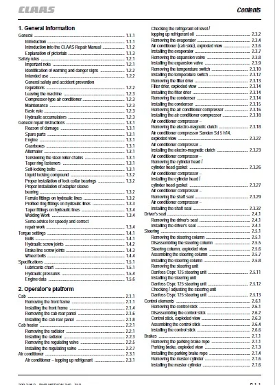
1 General information
General 111
Introduction 111
Introduction into the CLAAS Repair Manual 112
Explanation of pictorials 113
Safety rules 121
Important note 121
Identification of warning and danger signs 122
Intended use 122
General safety and accident prevention
regulations 122
Leaving the machine 123
Compressor-type air conditioner 123
Maintenance 123
Basic rule 123
Hydraulic accumulators 123
General repair instructions 131
Reason of damage 131
Spare parts 131
Engine 131
Gearboxes 131
Alternator 131
Tensioning the steel roller chains 131
Taper ring fasteners 131
Self-locking bolts 131
Liquid locking compound 132
Proper installation of lock collar bearings 132
Proper installation of adapter sleeve
bearing 132
Ferrule fittings on hydraulic lines 132
Profiled ring fittings on hydraulic lines 133
Taper fittings on hydraulic lines 134
Welding Work 134
Some advice for speedy and correct
repair work 134
Torque settings 141
Bolts 141
Hydraulic screw joints 142
Brake line screw joints 143
Wheel bolts 144
Specifications 151
Lubricants chart 151
Hydraulic pressures 154
Engine data 156
2 Operator’s platform
Cab 211
Removing the front frame 211
Installing the front frame 214
Removing the cab rear panel 216
Installing the cab rear panel 218
Cab heater 221
Removing the radiator 221
Installing the radiator 223
Removing the regulating valve 225
Installing the regulating valve 227
Air conditioner 231
Air conditioner – topping up refrigerant 231
Checking the refrigerant oil level /
topping up refrigerant oil 232
Removing the evaporator 234
Air conditioner (cab side), exploded view 236
Installing the evaporator 237
Removing the expansion valve 238
Installing the expansion valve 239
Removing the temperature switch 2310
Installing the temperature switch 2312
Removing the filter drier 2313
Filter drier, exploded view 2314
Installing the filter drier 2314
Removing the condenser 2314
Installing the condenser 2315
Removing the air conditioner compressor 2316
Installing the air conditioner compressor 2318
Air conditioner compressor –
Removing the electro-magnetic clutch 2318
Air conditioner compressor Sanden Sd 5 h14,
exploded view 2322
Air conditioner compressor –
Installing the electro-magnetic clutch 2323
Air conditioner compressor –
Removing the cylinder head /
cylinder head gasket 2326
Air conditioner compressor –
Installing the cylinder head /
cylinder head gasket 2327
Air conditioner compressor –
Removing the shaft seal 2329
Air conditioner compressor –
Installing the shaft seal 2332
Driver’s seat 241
Removing the driver’s seat 241
Installing the driver’s seat 241
Steering 251
Removing the steering column 251
Disassembling the steering column 255
Steering column, exploded view 256
Assembling the steering column 257
Installing the steering column 258
Removing the steering unit
Danfoss Ospc 125 steering unit 2511
Installing the steering unit
Danfoss Ospc 125 steering unit 2512
Checking / adjusting the steering unit
Danfoss Ospc 125 steering unit 2513
Control elements 261
Removing the control stick 261
Disassembling the control stick 262
Control stick, exploded view 263
Assembling the control stick 264
Installing the control stick 266
Brakes 271
Removing the parking brake rope 271
Parking brake, exploded view 273
Installing the parking brake rope 274
Removing the master cylinder 276
Installing the master cylinder 276
012 RHB MEDION 340 – 310 – 299 2160
Contents
Gear shift mechanism 281
Removing the gear shift mechanism 281
Disassembling the gear shift mechanism 282
Gear shift mechanism, exploded view 283
Assembling the gear shift mechanism 284
Installing the gear shift mechanism 285
Power supply 291
Removing the starter 291
Installing the starter 291
Removing the alternator 292
Installing the alternator 293
3 Threshing mechanism
Feed rake conveyor 311
Removing the feed rake conveyor 311
Installing the feed rake conveyor 313
Removing the wooden ledges 316
Installing the wooden ledges 318
Replacing the slide rails 3110
Replacing the feeder chains 3110
Removing the upper feed rake shaft 3113
Upper feed rake shaft, exploded view
(MEDION 340) 3119
Upper feed rake shaft, exploded view
(MEDION 330 – 310) 3120
Installing the upper feed rake shaft 3121
Removing the lower feed rake roller 3124
Disassembling the lower feed rake roller 3127
Lower feed rake roller, exploded view 3128
Assembling the lower feed rake roller 3129
Installing the lower feed rake roller 3130
Removing the intermediate drive shaft 3131
Installing the intermediate drive shaft 3136
Removing the (electric) reverser drive 3139
Reverser drive (electric), exploded view 3141
Installing the reverser drive (electric) 3142
Removing the reverser guard (hydraulic) 3143
Disassembling the reverser drive
(hydraulic) 3144
Reverser drive (hydraulic), exploded view 3145
Assembling the reverser drive (hydraulic) 3146
Threshing concave 321
Removing the stone trap 321
Installing the stone trap 322
Basic concave setting 324
Removing the concave 325
Installing the concave 329
Threshing drum 331
Removing the left threshing drum bearing 331
Disassembling the left threshing
drum bearing 335
Assembling the left threshing drum bearing 336
Installing the left threshing drum bearing 337
Removing the right threshing drum bearing 3311
Disassembling the right threshing
drum bearing 3315
Right threshing drum bearing,
exploded view 3316
Assembling the right threshing
drum bearing 3316
Installing the right threshing drum bearing 3317
Removing the threshing drum 3321
Replacing the beater bars 3325
Replacing the threshing drum shaft 3327
Threshing drum, exploded view 3328
Installing the threshing drum 3329
Impeller 341
Removing the left impeller bearing 341
Installing the left impeller bearing 343
Removing the right impeller bearing 344
Installing the right impeller bearing 346
Removing the impeller 348
Disassembling the impeller 349
Impeller, exploded view 3411
Assembling the impeller 3412
Installing the impeller 3413
4 Cleaning unit
Under-walker return floor 411
Removing the under-walker return floor 411
Front rocker arm, exploded view 412
Rear rocker arm, exploded view 412
Installing the under-walker return floor 412
Straw walker 421
Removing the straw walker racks 421
Installing the straw walker racks 423
Removing the front straw walker crankshaft 425
Installing the front straw walker crankshaft 427
Removing the rear straw walker crankshaft 428
Installing the rear straw walker crankshaft 4212
Disassembling the straw walker crankshafts
(for straw walker crankshafts
with ball bearings) 4215
Straw walker bearing, exploded view 4216
Assembling the straw walker crankshafts
(for straw walker crankshafts
with ball bearings) 4216
Intensive separation system 431
Removing the front intensive separation
system crankshaft 431
Installing the front intensive separation
system crankshaft 434
Removing the rear intensive separation
system crankshaft 438
Installing the rear intensive separation
system crankshaft 4310
Disassembling the intensive separation
system crankshaft 4313
Assembling the intensive separation
system crankshaft 4314
Replacing the intensive separation
system control shaft 4314
Replacing the agitator tine 4315
Sieve pan 441
Removing the upper sieves 441
Installing the upper sieves 441
Removing the lower sieves 441
299 2160 – RHB MEDION 340 – 310 013
Contents
Installing the lower sieves 441
Removing the sieve frame 442
Sieve frame, exploded view 445
Installing the sieve frame 446
Removing the sieve pan 449
Installing the sieve pan 4412
Preparation floor 451
Removing the preparation floor 451
Preparation floor, exploded view 455
Installing the preparation floor 456
Sieve frame linkage 461
Removing the 3-D sieve pan control system 461
Installing the 3-D sieve pan control system 461
3-D sieve frame suspension and sieve
pan control system, exploded view 462
Adjusting the 3-D sieve pan control system 463
Rocker arm drive 471
Removing the rocker arm drive 471
Rocker arm drive, exploded view 474
Installing the rocker arm drive 476
Cleaning fan 481
Removing the left and right cleaning
fan bearings 481
Self-aligning ball bearing, exploded view 484
Installing the left and right cleaning
fan bearings 484
Removing the centre cleaning fan bearing
(MEDION 340) 488
Centre cleaning fan bearing, exploded view
(MEDION 340) 488
Installing the centre cleaning fan bearing
(MEDION 340) 489
Removing the fan shaft
(MEDION 340) 489
Installing the fan shaft
(MEDION 340) 4812
Removing the fan rotors
(MEDION 340) 4815
Installing the fan rotors
(MEDION 340) 4816
Removing the fan housing
(MEDION 340) 4817
Installing the fan housing
(MEDION 340) 4818
Removing the wind boards
(MEDION 340) 4820
Installing the wind board
(MEDION 340) 4821
Removing the fan blast reduction kit
(MEDION 340) 4822
Installing the fan blast reduction kit
(MEDION 340) 4823
Removing the fan shaft
(MEDION 330 – 310) 4826
Installing the fan shaft
(MEDION 330 – 310) 4826
Replacing the fan blades
(MEDION 330 – 310) 4827
Removing the fan housing
(MEDION 330 – 310) 4828
Installing the fan housing
(MEDION 330 – 310) 4830
Removing the wind boards
(MEDION 330 – 310) 4831
Installing the wind boards
(MEDION 330 – 310) 4832
5 Grain delivery
Returns elevator 511
Removing the returns elevator chain 511
Installing the returns elevator chain 512
Removing the top returns auger 514
Installing the top returns auger 516
Removing the returns elevator 518
Disassembling the returns elevator 518
Assembling the returns elevator 5110
Installing the returns elevator 5112
Removing the bottom returns auger 5113
Installing the bottom returns auger 5116
Removing the returns elevator boot 5119
Installing the returns elevator boot 5121
Grain elevator 521
Removing the grain elevator chain 521
Installing the grain elevator chain 523
Removing the grain tank filler auger 524
Disassembling the grain tank filler auger
angle drive 526
Grain tank filler auger, exploded view 529
Assembling the grain tank filler auger
angle drive 5210
Installing the grain tank filler auger 5212
Removing the grain elevator head 5213
Disassembling the grain elevator head 5214
Grain elevator head, exploded view 5217
Assembling the grain elevator head 5218
Installing the grain elevator head 5220
Removing the grain elevator shaft 5221
Installing the grain elevator shaft 5222
Removing the grain auger 5223
Installing the grain auger 5227
Removing the grain elevator boot 5230
Installing the grain elevator boot 5231
Grain tank unloading 531
Removing the lateral augers
(MEDION 340 / 330) 531
Installing the lateral augers
(MEDION 340 / 330) 534
Removing the grain tank unloading auger 537
Installing the grain tank unloading auger 5311
Removing the grain tank unloading
tube auger 5313
Grain tank unloading tube, exploded view 5315
Installing the grain tank unloading
tube auger 5316
Removing the grain tank unloading tube 5318
Installing the grain tank unloading tube 5319
Replacing the wear ring 5321
014 RHB MEDION 340 – 310 – 299 2160
Contents
Chaff spreader 541
Removing the chaff spreader
flange housing 541
Disassembling the chaff spreader
flange housing 542
Chaff spreader, exploded view 544
Assembling the chaff spreader
flange housing 546
Installing the chaff spreader
flange housing 548
Removing the chaff spreader drive shaft 549
Disassembling the chaff spreader
drive shaft 5410
Assembling the chaff spreader drive shaft 5411
Installing the chaff spreader drive shaft 5411
6 Straw discharge
Straw spreader 611
Removing the straw spreader 611
Disassembling the straw spreader 612
Straw spreader, exploded view 615
Assembling the straw spreader 616
Installing the straw spreader 618
Straw chopper 621
Removing the right straw chopper bearing 621
Removing the left straw chopper bearing 623
Disassembling the left and right straw
chopper bearing 625
Assembling the left and right straw
chopper bearing 625
Installing the right straw chopper bearing 626
Installing the left straw chopper bearing 628
Removing the cutting cylinder 629
Cutting cylinder, exploded view 6212
Pre-assembling the cutting cylinder 6213
Installing the cutting cylinder 6214
7 Drives
Drive diagram 711
Drive diagram, left side 711
Drive diagram, right side 712
Drive belts on left side 721
Removing the cutterbar drive belt (1) 721
Installing and adjusting the cutterbar
drive belt (1) 723
Removing the compressor drive belt (2) 725
Installing and adjusting the compressor
drive belt (2) 726
Hydrostatic ground drive –
Removing the drive belt (3) 727
Hydrostatic ground drive –
Installing and adjusting the drive belt (3) 729
Working hydraulics pump drive –
Removing the drive belt (4) 7210
Working hydraulics pump drive –
Installing and adjusting the drive belt (4) 7211
Removing the threshing mechanism
drive belt (5) 7212
Installing and adjusting the threshing mechanism
drive belt (5) 7213
Removing the grain tank unloading drive
belt (6) 7215
Installing and adjusting the grain tank unloading
drive belt (6) 7216
Removing the sieve pan / fan intermediate
drive belt (7) 7217
Installing and adjusting the sieve pan /
fan intermediate drive belt (7) 7217
Removing the fan variable-speed belt (8) 7218
Installing the fan variable-speed belt (8) 7219
Removing the sieve pan intermediate
drive belt (9) 7219
Installing and adjusting the sieve pan
intermediate drive belt (9) 7220
Removing the sieve pan drive belt (10) 7220
Installing and adjusting the sieve pan
drive belt (10) 7221
Removing the straw walker
drive belt (11) 7221
Installing and adjusting the straw walker
drive belt (11) 7222
Removing the intensive separation system
drive belt (12) 7223
Installing and adjusting the intensive separation
system drive belt (12) 7224
Removing the straw spreader
drive belt (14) 7224
Installing and adjusting the straw spreader
drive belt (14) 7225
Removing the chaff spreader intermediate
drive belt (15) 7226
Installing and adjusting the chaff spreader
intermediate drive belt (15) 7226
Removing the chaff spreader
drive belt (16) 7227
Installing and adjusting the chaff spreader
drive belt (16) 7227
Right drive belt 731
Removing the straw chopper drive belt (20) 731
Installing and adjusting the straw chopper
drive belt (20) 732
Removing the straw chopper intermediate
drive belt (21) 733
Installing and adjusting the straw chopper
intermediate drive belt (21) 733
Removing the suction blower
drive belt (22) 734
Installing and adjusting the suction blower
drive belt (22) 735
Removing the threshing drum variable-speed
belt (23) 736
Installing the threshing drum variable-speed
belt (23) 737
Removing the threshing drum drive belt (24) 738
Installing and adjusting the threshing cylinder
drive belt (24) 7310
299 2160 – RHB MEDION 340 – 310 015
Contents
Removing the threshing drum variable-speed belt (25)
(without intermediate drive) 7312
Installing the threshing drum variable-speed belt (25)
(without intermediate drive) 7313
Removing the rotary chaff screen
drive belt (26) 7314
Installing the rotary chaff screen
drive belt (26) 7315
Removing the rotary chaff screen intermediate
drive belt (27) 7315
Installing and adjusting the rotary chaff screen
intermediate drive belt (27) 7316
Removing the alternator /
fan drive belt (28) 7317
Installing the alternator /
fan drive belt (28) 7317
Removing the grain elevator top
drive chain (30) 7318
Installing the grain elevator top
drive chain (30) 7318
Removing the grain tank unloading
intermediate drive chain (31) 7319
Installing and adjusting the grain tank unloading
intermediate drive chain (31) 7319
Removing the grain tank unloading
intermediate drive chain (32)
(MEDION 340 / 330) 7319
Installing and adjusting the grain tank
unloading intermediate drive chain (32)
(MEDION 340 / 330) 7320
Removing the returns drive chain (33) 7320
Installing and adjusting the returns
drive chain (33) 7321
Treshing mechanism drive on left side 741
Removing the threshing mechanism drive
jockey pulley 741
Treshing mechanism drive jockey pulley,
exploded view 742
Installing the threshing mechanism
drive jockey pulley 742
Removing the threshing mechanism
drive V-belt pulley 743
Installing the threshing mechanism
drive V-belt pulley 743
Right treshing mechanism drive 751
Removing the threshing drum variable-speed
drive (hydraulic) 751
Disassembling the threshing drum variable-speed
drive (hydraulic) 753
Threshing drum variable-speed drive (hydraulic),
exploded view 755
Assembling the threshing drum variable-speed
drive (hydraulic) 757
Installing the threshing drum variable-speed
drive (hydraulic) 759
Removing the threshing drum variable-speed
drive (spring-loaded) 7511
Disassembling the threshing drum variable-speed
drive (spring-loaded) 7513
Threshing drum variable-speed drive (spring-loaded),
exploded view 7516
Assembling the threshing drum variable-speed
drive (spring-loaded) 7518
Installing the threshing drum variable-speed
drive (spring-loaded) 7521
Removing the threshing drum variable-speed
drive intermediate drive 7525
Disassembling the threshing drum variable-speed
intermediate drive 7526
Threshing drum variable-speed intermediate drive,
exploded view 7528
Assembling the threshing drum variable-speed
intermediate drive 7529
Installing the threshing drum variable-speed drive
intermediate drive 7531
Removing the drum drive jockey pulley
(with intermediate drive) 7532
Drum drive jockey pulley, exploded view
(with intermediate drive) 7532
Installing the drum drive jockey pulley
(with intermediate drive) 7533
Removing the threshing drum reduction
gearbox 7534
Disassembling the threshing drum reduction
gearbox 7535
Threshing drum reduction gearbox,
exploded view 7540
Assembling the threshing drum reduction
gearbox 7542
Installing the threshing drum reduction
gearbox 7547
Removing the drum drive V-belt pulley 7549
Installing the drum drive V-belt pulley 7550
Cutterbar drive 761
Removing the cutterbar clutch 761
Cutterbar clutch, exploded view 765
Installing the cutterbar clutch 767
Removing the cutterbar drive
jockey pulley 7611
Cutterbar drive jockey pulley,
exploded view 7611
Installing the cutterbar drive jockey pulley 7612
Removing the cutterbar drive guide roller 7613
Cutterbar drive guide roller, exploded view
(MEDION 340) 7613
Cutterbar drive guide roller, exploded view
(MEDION 330 – 310) 7613
Installing the cutterbar drive guide roller 7614
Removing the front cutterbar
drive V-belt pulley 7615
Installing the front cutterbar
drive V-belt pulley 7616
Removing the cutterbar drive slip clutch 7617
Disassembling the cutterbar
drive slip clutch 7618
Cutterbar drive slip clutch, exploded view 7620
Assembling the cutterbar drive slip clutch 7620
Installing the cutterbar drive slip clutch 7622
016 RHB MEDION 340 – 310 – 299 2160
Contents
Straw walker drive 771
Removing the straw walker
drive jockey pulley 771
Straw walker drive jockey pulley,
exploded view 771
Installing the straw walker
drive jockey pulley 772
Removing the intensive separation
system jockey pulley 773
Intensive separation system jockey pulley,
exploded view 773
Installing the intensive separation
system jockey pulley 774
Removing the intensive separation
system guide roller 775
Intensive separation system guide roller,
exploded view 775
Installing the intensive separation system guide roller 776
Sieve pan drive 781
Removing the sieve pan /
fan drive intermediate drive jockey pulley 781
Sieve pan / fan drive intermediate drive jockey pulley,
exploded view 781
Installing the sieve pan /
fan drive intermediate drive jockey pulley 782
Removing the sieve pan / straw walker drive
intermediate drive guide roller 783
Sieve pan / straw walker drive intermediate drive
guide roller, exploded view 783
Installing the sieve pan / straw walker drive
intermediate drive guide roller 784
Removing the sieve pan / straw walker drive
intermediate drive V-belt pulley 785
Disassembling the sieve pan / straw walker drive
intermediate drive V-belt pulley 786
Sieve pan / straw walker drive intermediate
drive V-belt pulley, exploded view 787
Assembling the sieve pan / straw walker drive
intermediate drive V-belt pulley 787
Installing the sieve pan / straw walker drive
intermediate drive V-belt pulley 789
Removing the sieve pan drive guide roller 7810
Sieve pan drive guide roller, exploded view 7810
Installing the sieve pan drive guide roller 7811
Fan drive 791
Removing the fan adjustment (electric) 791
Disassembling the fan adjustment (electric) 792
Fan adjustment (electric), exploded view 793
Assembling the fan adjustment (electric) 794
Installing the fan adjustment (electric) 796
Removing the fan variable-speed
drive (electric) 797
Disassembling the fan variable-speed
drive (electric) 798
Fan variable-speed drive (electric), exploded view
(MEDION 340) 7910
Fan variable-speed drive (electric), exploded view
(MEDION 330 – 310) 7910
Assembling the fan variable-speed
drive (electric) 7911
Installing the fan variable-speed
drive (electric) 7913
Aligning the fan variable-speed pulleys 7916
Removing the fan variable-speed
drive (spring-loaded) 7917
Disassembling the spring-loaded fan
variable-speed drive 7918
Fan variable-speed drive (spring-loaded),
exploded view 7919
Assembling the spring-loaded fan
variable-speed drive 7920
Installing the fan variable-speed drive
(spring-loaded) 7922
Chaff spreader drive 7101
Removing the chaff spreader
drive bracket 7101
Disassembling the chaff spreader
drive bracket 7102
Chaff spreader bracket, exploded view 7103
Assembling the chaff spreader
drive bracket 7103
Installing the chaff spreader drive bracket 7105
Removing the chaff spreader
drive jockey pulley 7106
Chaff spreader drive jockey pulley,
exploded view 7106
Installing the chaff spreader
drive jockey pulley 7107
Grain tank drive 7111
Removing the grain tank
drive jockey pulley 7111
Grain tank drive jockey pulley,
exploded view 7111
Installing the grain tank drive jockey pulley 7112
Removing the grain tank drive
intermediate drive shaft 7112
Grain tank drive intermediate drive shaft,
exploded view 7115
Installing the grain tank drive
intermediate drive shaft 7116
Removing the grain tank
drive safety clutch 7118
Disassembling the grain tank
drive safety clutch 7119
Grain tank drive safety clutch,
exploded view 71110
Assembling the grain tank
drive safety clutch 71110
Installing the grain tank drive safety clutch 71111
Removing the equalising auger 71111
Disassembling the equalising auger 71113
Equalising auger, exploded view 71115
Assembling the equalising auger 71116
Installing the equalising auger 71118
Straw chopper drive 7121
Removing the straw chopper intermediate
drive jockey pulley 7121
299 2160 – RHB MEDION 340 – 310 017
Contents
Straw chopper intermediate drive jockey pulley,
exploded view
(MEDION 340) 7121
Straw chopper intermediate drive jockey pulley,
exploded view
(MEDION 330 – 310
with threshing drum reduction gearbox) 7122
Straw chopper intermediate drive jockey pulley,
exploded view
(MEDION 330 – 310
without threshing drum reduction gearbox) 7122
Installing the straw chopper intermediate
drive jockey pulley 7123
Removing the straw chopper drive
intermediate drive 7124
Disassembling the straw chopper
drive intermediate drive 7125
Straw chopper drive intermediate drive,
exploded view
(MEDION 340) 7127
Assembling the straw chopper drive
intermediate drive 7128
Installing the straw chopper drive
intermediate drive 71210
Removing the straw chopper drive
jockey pulley (stage 1) 71211
Straw chopper drive jockey pulley, exploded view
(stage 1) 71211
Installing the straw chopper drive jockey pulley
(stage 1) 71212
Removing the straw chopper drive jockey pulley
(stage 2) 71213
Straw chopper drive jockey pulley, exploded view
(stage 2) 71213
Installing the straw chopper drive jockey pulley
(stage 2) 71214
Removing the straw chopper drive guide roller
(stage 2) 71215
Straw chopper drive guide roller, exploded view
(stage 2) 71215
Installing the straw chopper drive guide roller
(stage 2) 71216
Removing the cutting cylinder drive 71217
Cutting cylinder drive, exploded view 71217
Installing the cutting cylinder drive 71218
Straw spreader drive 7131
Removing the straw spreader tensioning
device 7131
Disassembling the straw spreader tensioning
device 7132
Straw spreader tensioning device,
exploded view 7133
Assembling the straw spreader tensioning
device 7134
Installing the straw spreader tensioning
device 7135
Ground drive 7141
Removing the ground drive jockey pulley 7141
Ground drive jockey pulley, exploded view 7141
Installing the ground drive jockey pulley 7142
Removing the actuating rope 7142
Installing the actuating rope 7143
Rotary chaff screen drive 7151
Removing the rotary chaff screen
drive shaft 7151
Disassembling the rotary chaff screen
drive shaft 7152
Rotary chaff screen drive, exploded view 7156
Assembling the rotary chaff screen
drive shaft 7157
Installing the rotary chaff screen
drive shaft 7159
Rotary chaff screen suction blower 7161
Removing the rotary chaff screen
suction blower 7161
Disassembling the rotary chaff screen
suction blower 7161
Rotary chaff screen suction blower,
exploded view 7164
Assembling the rotary chaff screen
suction blower 7165
Installing the rotary chaff screen
suction blower 7167
Drive axle 7171
Removing the drive axle 7171
Installing the drive axle 7175
Manual gearbox 7181
Removing the manual gearbox 7181
Disassembling the manual gearbox
and the differential 7186
Manual gearbox, exploded view 71815
Differential, exploded view 71816
Assembling the manual gearbox
and the differential 71817
Installing the manual gearbox 71831
Brakes 7191
Removing the brake shoes
of the parking brake 7191
Installing the brake shoes
of the parking brake 7192
Bleeding the brake system 7193
Removing the brake linings
of the foot brake 7194
Installing the brake linings
of the foot brake 7196
Removing the fixed caliper 7197
Installing the fixed caliper 7199
Removing the brake disc 71911
Installing the brake disc 71912
Final drives 7201
Removing the axle drives 7201
Installing the axle drive 7203
Disassembling the axle drive
(MEDION 340) 7205
Axle drive, exploded view
(MEDION 340) 72014
Assembling the axle drive
(MEDION 340) 72016
018 RHB MEDION 340 – 310 – 299 2160
Contents
Disassembling the axle drive
(MEDION 330 – 310) 72026
Axle drive, exploded view
(MEDION 330 – 310) 72032
Assembling the axle drive
(MEDION 330 – 310) 72033
Rear axle 7211
Removing the wheel bearings
(205 m rear axle) 7211
Wheel bearing, exploded view
(205 m rear axle) 7213
Installing the wheel bearings
(205 m rear axle) 7213
Removing the stub axles
(205 m rear axle) 7215
Stub axle, exploded view
(205 m rear axle) 7218
Installing the stub axles
(205 m rear axle) 7218
Removing the wheel bearings
(240 m rear axle / adjustable rear axle) 72110
Wheel bearing, exploded view
(240 m rear axle / adjustable rear axle) 72112
Installing the wheel bearings
(240 m rear axle / adjustable rear axle) 72113
Removing the stub axles
(240 m rear axle / adjustable rear axle) 72115
Stub axle, exploded view
(240 m rear axle / adjustable rear axle –
MEDION 330 – 310) 72118
Stub axle, exploded view
(adjustable rear axle – MEDION 340) 72118
Installing the stub axles
(240 m rear axle / adjustable rear axle) 72118
Adjusting the rear axle stops
(205 m rear axle, 240 m rear axle,
adjustable rear axle) 72121
Adjusting the rear axle stops
(CLAAS 4-Trac axle) 72122
Adjusting the track width 72123
Removing the rear axle 72125
Installing the rear axle 72127
Removing the CLAAS 4-Trac axle 72129
Installing the CLAAS 4-Trac axle 72131
Removing the CLAAS 4-Trac system 72134
CLAAS 4-Trac system, exploded view 72137
Installing the CLAAS 4-Trac system 72138
Removing the stub axle housings
(CLAAS 4-Trac system) 72140
Installing the stub axle housings
(CLAAS 4-Trac system) 72142
8 Machine body
9 Hydraulic system
Hydraulic tank 911
Removing the hydraulic tank 911
Hydraulic tank, exploded view 913
Installing the hydraulic tank 913
Checking the hydraulic oil level
(Hydrostatic ground drive
and working hydraulics) 915
Hydraulic oil cooler 921
Removing the hydraulic oil cooler 921
Installing the hydraulic oil cooler 922
Hydraulic pump 931
Removing the double pump 931
Disassembling the double pump 932
Double pump, exploded view 933
Assembling the double pump 933
Installing the double pump 934
Removing the hydraulic variable-displacement pump
(Linde HPV 105) 937
Hydrostatic ground drive, exploded view
(Linde HPV 105) 9310
Installing the hydraulic variable-displacement pump
(Linde HPV 105) 9311
Venting the hydrostatic system 9316
Bleeding the CLAAS 4-Trac system 9317
Hydraulic motor 941
Removing the ground drive hydraulic motor
(Linde HMV 105) 941
Installing the ground drive hydraulic motor
(Linde HMV 105) 943
Low-pressure hydraulic system control valves 951
Removing the low-pressure hydraulic system
solenoid valve 951
Low-pressure hydraulic system solenoid valve,
exploded view 954
Installing the low-pressure hydraulic system
solenoid valve 955
Removing the low-pressure hydraulic system
pressure relief valve 956
Installing the low-pressure hydraulic system
pressure relief valve 957
Adjusting / checking the low-pressure hydraulic
system pressure relief valve 957
Removing the 3-D sieve pan
pendulum control 958
Disassembling the 3-D sieve pan
pendulum control 958
3-D sieve pan pendulum control,
exploded view 9510
Assembling the 3-D sieve pan
pendulum control 9511
Installing the 3-D sieve pan
pendulum control 9512
Working hydraulics control valves 961
Removing the grain tank unloading tube lock-up
valve unit 961
Grain tank unloading tube lock-up valve unit,
exploded view 961
Installing the grain tank unloading tube lock-up
valve unit 962
Removing the CLAAS Auto-Contour lock-up
valve unit 963
CLAAS Auto-Contour lock-up valve unit,
exploded view 963
299 2160 – RHB MEDION 340 – 310 019
Contents
Installing the CLAAS Auto-Contour lock-up
valve unit 964
Removing the working hydraulics pressure
relief valve 965
Disassembling the working hydraulics pressure
relief valve 965
Working hydraulics pressure relief valve,
exploded view 967
Assembling the working hydraulics pressure
relief valve 968
Installing the working hydraulics pressure relief valve 969
Adjusting / checking the working hydraulics pressure
relief valve 9610
Removing the front working hydraulics
valve block 9611
Installing the front working hydraulics
valve block 9612
Removing the 3/3-way drum speed adjustment valve 9612
Disassembling the 3/3-way drum speed
adjustment valve 9613
3/3-way drum speed adjustment valve,
exploded view 9615
Assembling the 3/3-way drum speed
adjustment valve 9616
Installing the 3/3-way drum speed adjustment valve 9617
Removing the 4/3-way hydraulic fore and aft reel
adjustment and CLAAS Auto-Contour solenoid valve 9618
4/3-way hydraulic fore and aft reel adjustment and
CLAAS Auto-Contour solenoid valve, exploded view 9619
Installing the 4/3-way hydraulic fore and aft reel adjustment
and CLAAS Auto-Contour solenoid valve 9620
Removing the rear working hydraulics
valve block 9621
Installing the rear working hydraulics
valve block 9623
Removing the 3/3-way raise / lower reel and
raise / lower cutterbar solenoid valve 9623
Disassembling the 3/3-way raise / lower reel and
raise / lower cutterbar solenoid valve 9624
3/3-way raise / lower reel and raise / lower cutterbar
solenoid valve, exploded view 9629
Assembling the 3/3-way
raise/lower reel and
raise/lower cutterbar solenoid valve 9630
Installing the 3/3-way
raise / lower reel and
raise / lower cutterbar solenoid valve 9631
Removing the 4/3-way swing grain tank
unloading tube solenoid valve 9632
4/3-way swing grain tank unloading tube
solenoid valve, exploded view 9633
Installing the 4/3-way swing grain tank unloading tube
solenoid valve 9634
Removing the CLAAS Auto-Contour flow
control valve 9635
CLAAS Auto-Contour flow control valve,
exploded view 9635
Installing the CLAAS Auto-Contour flow
control valve 9636
Removing the CLAAS Autopilot
master valve 9636
CLAAS Autopilot master valve,
exploded view 9637
Installing the CLAAS Autopilot
master valve 9637
Removing the CLAAS Autopilot solenoid
valve block 9638
CLAAS Autopilot solenoid valve block,
exploded view 9640
Installing the CLAAS Autopilot solenoid
valve block 9641
Low-pressure hydraulic system
hydraulic cylinder 971
Removing the threshing mechanism circuit
hydraulic cylinder 971
Disassembling the threshing mechanism
circuit hydraulic cylinder 972
Threshing mechanism circuit hydraulic cylinder,
exploded view 973
Assembling the threshing mechanism circuit
hydraulic cylinder 974
Installing the threshing mechanism circuit
hydraulic cylinder 975
Removing the grain tank circuit hydraulic cylinder
(MEDION 340) 976
Installing the grain tank circuit hydraulic cylinder
(MEDION 340) 977
Removing the grain tank circuit hydraulic cylinder
(MEDION 330 – 310) 978
Installing the grain tank circuit hydraulic cylinder
(MEDION 330 – 310) 979
Disassembling the grain tank circuit
hydraulic cylinder 9710
Grain tank circuit hydraulic cylinder,
exploded view 9711
Assembling the grain tank circuit
hydraulic cylinder 9711
Removing the cutterbar clutch
rotary coupling 9712
Disassembling the cutterbar clutch
rotary coupling 9713
Assembling the cutterbar clutch
rotary coupling 9715
Installing the cutterbar clutch
rotary coupling 9717
Removing the cutterbar clutch
hydraulic cylinder 9717
Disassembling the cutterbar clutch
hydraulic cylinder 9718
Rotary coupling / Cutterbar clutch hydraulic cylinder,
exploded view 9719
Assembling the cutterbar clutch
hydraulic cylinder 9720
Installing the cutterbar clutch
hydraulic cylinder 9722
Removing the 3-D cleaning system
hydraulic cylinder 9722
0110 RHB MEDION 340 – 310 – 299 2160
Contents
Disassembling the 3-D cleaning system
hydraulic cylinder 9723
3-D sieve pan control system hydraulic cylinder,
exploded view 9725
Assembling the 3-D cleaning system
hydraulic cylinder 9726
Installing the 3-D cleaning system
hydraulic cylinder 9727
Working hydraulics hydraulic cylinders 981
Removing the cutterbar cylinders 981
Disassembling the cutterbar cylinder 982
Cutterbar cylinder, exploded view 984
Assembling the cutterbar cylinders 985
Installing the cutterbar cylinder 987
Removing the CLAAS Auto-Contour
hydraulic cylinder 988
Disassembling the CLAAS Auto-Contour
hydraulic cylinder 988
CLAAS Auto-Contour hydraulic cylinder,
exploded view 9810
Assembling the CLAAS Auto-Contour
hydraulic cylinder 9811
Installing the CLAAS Auto-Contour
hydraulic cylinder 9813
Removing the grain tank unloading tube
hydraulic cylinder 9814
Disassembling the grain tank unloading tube
hydraulic cylinder 9815
Grain tank unloading tube hydraulic cylinder,
exploded view 9817
Assembling the grain tank unloading tube
hydraulic cylinder 9818
Installing the grain tank unloading tube
hydraulic cylinder 9820
Removing the drum variable-speed drive
rotary coupling 9821
Disassembling the drum variable-speed drive
rotary coupling 9822
Assembling the drum variable-speed drive
rotary coupling 9824
Installing the drum variable-speed drive
rotary coupling 9825
Removing the drum variable-speed drive
hydraulic cylinder 9826
Disassembling the drum variable-speed drive
hydraulic cylinder 9826
Drum variable-speed drive hydraulic cylinder,
exploded view 9827
Assembling the drum variable-speed drive
hydraulic cylinder 9828
Installing the drum variable-speed drive
hydraulic cylinder 9829
Removing the reverser drive
hydraulic cylinder 9829
Disassembling the reverser drive
hydraulic cylinder 9830
Reverser drive hydraulic cylinder,
exploded view 9831
Assembling the reverser drive
hydraulic cylinder 9832
Installing the reverser drive
hydraulic cylinder 9833
Adjusting the reverser drive
hydraulic cylinder 9834
Steering hydraulics hydraulic cylinders 991
Removing the steering cylinders
(for 205 m rear axle) 991
Disassembling the steering cylinders
(for 205 m rear axle) 992
Steering cylinder, exploded view
(for 205 m rear axle) 993
Assembling the steering cylinders
(for 205 m rear axle) 994
Assembling the steering cylinders
(for 205 m rear axle) 996
Removing the steering cylinders
(for adjustable rear axle,
for CLAAS 4-Trac axle) 997
Disassembling the steering cylinders
(for adjustable rear axle,
for CLAAS 4-Trac axle) 998
Steering cylinder, exploded view
(for adjustable rear axle,
for CLAAS 4-Trac axle) 999
Assembling the steering cylinders
(for adjustable rear axle,
for CLAAS 4-Trac axle) 9910
Installing the steering cylinders
(for adjustable rear axle,
for CLAAS 4-Trac axle) 9912
10 Engine
Engine output 1011
Removing the engine output shaft
(DAIMLER CHRYSLER OM 906 LA) 1011
Engine output, exploded view
(DAIMLER CHRYSLER OM 906 LA) 1018
Installing the engine output shaft
(DAIMLER CHRYSLER OM 906 LA) 1019
Engine 1021
Removing the engine
(DAIMLER CHRYSLER OM 906 LA) 1021
Installing the engine
(DAIMLER CHRYSLER OM 906 LA) 1028
Fuel system 1031
Removing the fuel tank 1031
Fuel tank, exploded view 1033
Installing the fuel tank 1034
Engine cooling system 1041
Removing the radiator 1041
Engine cooling system, exploded view
(DaimlerChrysler OM 906 LA) 1044
Installing the radiator 1045
Removing the charge air cooler 1048
Installing the charge air cooler 10410
IMAGES PREVIEW OF THE MANUAL:
CLAAS MEDION 340 MEDION 330 MEDION 320 MEDION 310 REPAIR MANUAL- PDF DOWNLOAD:
PLEASE NOTE:
- This is the SAME manual used by the dealers to troubleshoot any faults in your vehicle. This can be yours in 2 minutes after the payment is made.
- Contact us at [email protected] should you have any queries before your purchase or that you need any other service / repair / parts operators manual.
S.M