CLAAS MEGA 360 – 350 Technical & Electric System Manual – PDF DOWNLOAD
Original price was: $80.00.$28.95Current price is: $28.95.
CLAAS MEGA 360 – 350 Technical & Electric System Manual – PDF DOWNLOAD
Up to serial number:
845 00386
835 00360
Description
CLAAS MEGA 360 – 350 Technical & Electric System Manual – PDF DOWNLOAD
DESCRIPTION:
CLAAS MEGA 360 – 350 Technical & Electric System Manual – PDF DOWNLOAD
Description of function
A plus potential (+30) is fed in via the central power supply from the positive terminal of battery (G1) and/or from generator (G2) pin 30. The minus terminal of battery (G1) and the central earthing point (-31) are connected to the machine chassis.
Ignition ON
With the ignition switched on, battery plus (+30) is passed on as switched plus (+15) via the ignition switch (S64).
Electric starting motor circuit
The start relay K11 is used as safety start switch only if the ground speed control lever is in neutral position and consequently the ground speed control lever safety start switch (Z57) is closed. At the same time, the threshing mechanism must be switched off at switch S 25. When the power supply is applied at the electric starting motor, the start relay (K11/87) applies a signal voltage in parallel to the electronic engine control module (A15) and sets the electronic injection unit to start mode.
Generator release
With the generator (G2) running, the generator release relay (K61) switches battery plus (+30) on to generator release relay (K61/87). Perfect generator function therefore is the pre-condition for the system operating voltage.
Generator charging light
With the ignition switched on, the generator charging light (H19) must light up in order to excite the generator (G2) internally. When the generator charging light (H19) lights up while the engine/generator are running, no charging voltage is generated a total failure of the generator must be assumed. In this case, buzzer H 44 and the signal lights “Stop” (H42) in the operations display screen and/or the warning light (H45) on the vehicle information unit are permanently activated as a warning (see circuit diagram 3a and/or 3b).
TABLE OF CONTENTS:
CLAAS MEGA 360 – 350 Technical & Electric System Manual – PDF DOWNLOAD
Technical Systems Electric System Mega 360 – 350 1
Layout of electric circuit diagrams 3
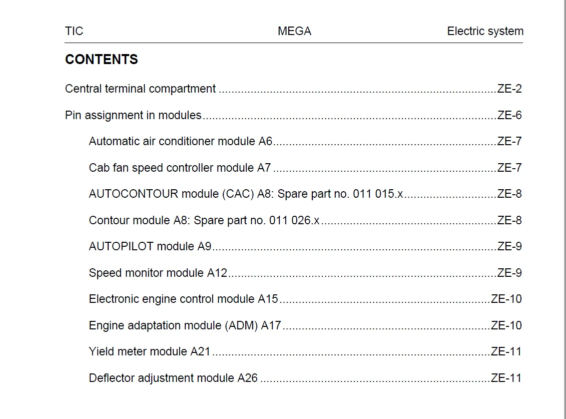
Contents 5
Central terminal compartment 10
Pin assignment in modules 13
Automatic air conditioner module A6: 15
Cab fan speed controller module A7: 15
AUTOCONTOUR module (CAC) A8: Spare part no 011 015x 16
Contour module A8: Spare part no 011 026x 16
AUTOPILOT module A9: 17
Speed monitor module A12: 17
Electronic engine control module A15: 18
Engine adaptation module (ADM) A17: 18
Yield meter module A21: 19
Deflector adjustment module A26: 19
Circuit diagrams 01a – 50a 21
1a Main power supply, Diesel engine electric starting motor 21
2a Starting the diesel engine, diesel engine speed adjustment 27
3a Diesel engine cut-off system 31
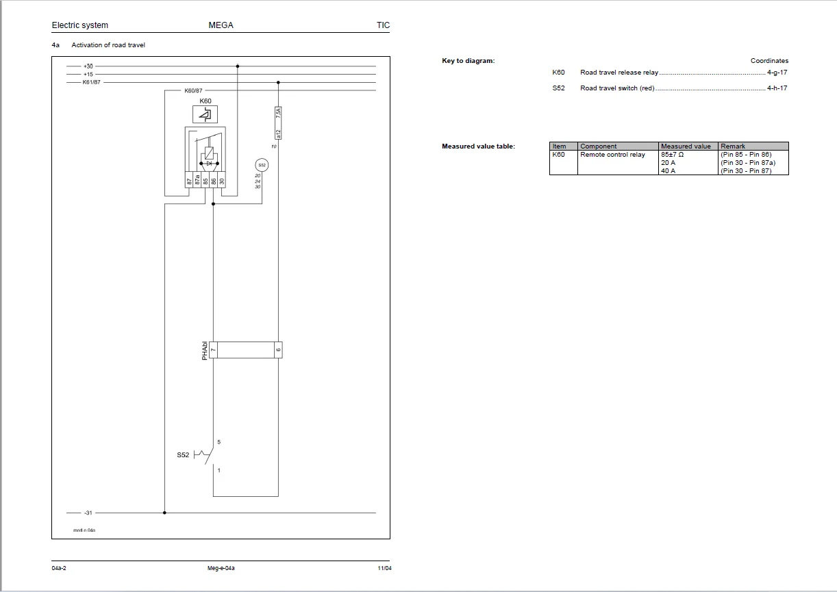
4a Activation of road travel 37
5a Fieldwork computer 41
7a Threshing mechanism circuit up to serial no 835 00146, 845 00123 47
7b Threshing mechanism circuit from serial no 835 00147, 845 00124 51
10a Fan variable-speed drive 55
12a Deflector adjustment, performance monitor 61
14a Swinging the grain tank unloading tube 67
15a Grain tank unloading 71
17a Front attachment drive, reverser drive (electric) 75
17b Front attachment drive, reverser drive (hydraulic) up to serial no 835 00146, 845 00123 79
17c Front attachment drive, Reverser drive (hydraulic) from serial no 835 00147, 845 00124 83
19a Reel variable-speed drive 87
20a Front attachment raise/lower, transverse control 91
21a Reel adjustment 95
21b Folding the maize picker / snapping plate adjustment 99
23a Folding the cutterbar 103
24a AUTOCONTOUR (CAC) 107
24b CONTOUR 113
25a Speed monitoring 117
26a Machine monitoring up to serial no 835 00146, 845 00123121
26b Machine monitoring from serial no 835 00147, 845 00124127
27a Yield meter 133
28a AUTOPILOT 137
29a All-wheel drive 145
30a Grain tank full indicator / warning beacon 149
31a Turn flasher system 153
32a Main light circuit, position light 159
33a Dipped headlights, dipped headlights changeover 165
34a Work lights up to serial no 835 00146, 845 00123169
34b Work lights from serial no 835 00147 845 00124175
35a Grain tank, sieve pan and returns lighting, reversing horn, brake light 181
36a Interior lights, instrument lighting 185
37a Windscreen wiper 191
38a Compressor-type air conditioner, cab fan 195
38b Automatic air conditioner 199
39a Air-suspended seat compressor 203
40a Additional sockets 207
50a Electric mirror adjustment 211
Component grid 217
Index220
A – E220
F – R221
S – Y222
0299 5052224
IMAGES PREVIEW OF THE MANUAL:
CLAAS MEGA 360 – 350 TECHNICAL & ELECTRIC SYSTEM MANUAL – PDF DOWNLOAD:
https://vimeo.com/676539820
PLEASE NOTE:
- This is not a physical manual but a digital manual – meaning no physical copy will be couriered to you. The manual can be yours in the next 2 mins as once you make the payment, you will be directed to the download page IMMEDIATELY.
- This is the same manual used by the dealers inorder to diagnose your vehicle of its faults.
- Require some other service manual or have any queries: please WRITE to us at [email protected]
S.M