CLAAS MEGA 370 MEGA 360 MEGA 350 Operator’s Manual – PDF DOWNLOAD
Original price was: $89.95.$29.95Current price is: $29.95.
CLAAS MEGA 370 MEGA 360 MEGA 350 Operator’s Manual – PDF DOWNLOAD
Description
CLAAS MEGA 370 MEGA 360 MEGA 350 Operator’s Manual – PDF DOWNLOAD
DESCRIPTION:
CLAAS MEGA 370 MEGA 360 MEGA 350 Operator’s Manual – PDF DOWNLOAD
INTRODUCTION :
This manual applies to CLAAS MEGA 370, MEGA 360 and MEGA 350 Combine Harvesters. It is primarily intended for the machine operator and contains information on using, setting and operating the machine. In general, texts and pictures apply to all machine models covered by this manual.
- The information given applies equally, except where reference is made to a particular model in captions to the pictures or in the main text. Operation and maintenance of important accessories is also covered by this manual. Please read the instructions which apply to the appropriate accessories on your machine.
- Provided all instructions regarding maintenance and care of your machine are followed, you can count on many years of reliable service.
- Please have your authorised CLAAS dealer carry out the recommended regular inspections. The neglecting of regular maintenance and proper machine operation lead to reduced performance and loss of time. If proper operation and careful maintenance is ensured, your combine harvester, which incorporates latest harvesting technology, will render you excellent service.
This Operator’s Manual as well as the manuals listed below can be ordered from your CLAAS Dealer:
• Threshing Instructions for special crops
• Fitting and Operating Instructions for accessories
TABLE OF CONTENTS:
CLAAS MEGA 370 MEGA 360 MEGA 350 Operator’s Manual – PDF DOWNLOAD
1 Introduction
Introduction 1 1 1
2 Contents
Contents 2 1 1
3 General information
Road traffic regulations 3 1 1
Important notice 3 2 1
Identification plate / Serial number 3 3 1
Identification plate 3 3 2
Machine serial number 3 3 2
Engine serial number
DAIMLER CHRYSLER OM 906 LA 3 3 2
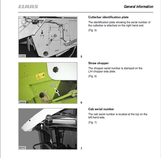
Cutterbar identification plate 3 3 3
Straw chopper 3 3 3
Cab serial number 3 3 3
4 Safety Rules
Safety Rules 4 1 1
Cylinder safety lock 4 1 4
Fire extinguisher 4 1 4
Battery isolating switch 4 1 5
Wheel chock
(not for all countries) 4 1 5
Apply a wheel chock 4 1 5
Safety decals with pictorials 4 2 1
5 Specifications
CLAAS MEGA 370 / 360 5 1 1
CLAAS MEGA 350 5 2 1
Safety features 5 3 1
Front attachments – weights and dimensions 5 4 1
Sectional view of machine 5 5 1
Description and function 5 5 2
Cutterbar 5 5 2
Threshing mechanism 5 5 3
Straw walkers 5 5 3
Cleaning unit 5 5 3
Disawning 5 5 3
Basic rules for combining 5 5 4
6 Prior to operation
Carry out prior to initial operation 6 1 1
Cab 6 2 1
Cab with automatic air conditioner 6 2 1
Automatic air conditioner 6 2 2
Operating and display elements 6 2 2
Putting the automatic air conditioner into operation 6 2 3
Setting the cab temperature 6 2 4
Manually setting the evaporator blower speed 6 2 4
Activating ECON operating mode 6 2 5
Deactivating ECON operating mode 6 2 5
REHEAT operation
(Dehumidify cab windows) 6 2 6
Displaying the outside temperature 6 2 7
Changing the temperature display to °Fahrenheit 6 2 7
Floor heating 6 2 7
Display of malfunction:
error in thermometer F0 (cab, blue) 6 2 8
Display of malfunction:
error in thermometer F1 (exhaust, yellow) 6 2 8
Display of malfunction:
error in thermometer F2 (outside, red) 6 2 8
Cab with air conditioner 6 2 9
Cab with fan 6 2 10
Cab with fan and air conditioner 6 2 10
Cab with fan and heater 6 2 12
Floor heating 6 2 12
Reheat system (Dehumidify cab windows) 6 2 12
Malfunction, possible cause or remedy –
air conditioner 6 2 13
Opening and closing the cab roof 6 2 15
Opening the cab roof 6 2 15
Closing the cab roof 6 2 15
Operator’s platform 6 3 1
Steering column 6 3 2
Ignition switch 6 3 2
Vehicle information unit 6 3 3
Function of vehicle information unit 6 3 4
Operations display screen 6 3 5
Function of operations display screen 6 3 6
Switch console (up to serial no ) 6 3 7
Switch console (from serial no ) 6 3 8
Multifunction lever (up to serial no ) 6 3 9
Multifunction lever (from serial no ) 6 3 9
Central terminal compartment 6 3 10
Plug-in type module (P) CLAAS Autopilot 6 3 10
Positioning the cutterbar /
maize picker head for road travel 6 3 11
Steering column adjustment 6 3 11
Operator’s seat “air suspension” (option) 6 3 12
Height adjustment 6 3 12
Weight adjustment 6 3 12
Seat angle adjustment 6 3 13
Seat depth adjustment 6 3 13
Lumbar support 6 3 13
Armrest angle adjustment 6 3 13
Horizontal adjustment of operator’s seat 6 3 13
Operator’s seat, mechanical (option) 6 3 14
Weight adjustment 6 3 14
Height adjustment 6 3 14
Seat angle adjustment 6 3 15
Seat depth adjustment 6 3 15
Lumbar support 6 3 15
Armrest angle adjustment 6 3 15
Horizontal adjustment of operator’s seat 6 3 15
Master safety switch in driver’s seat
(from serial no ) 6 3 15
Access ladder 6 3 16
Front ladder 6 3 16
Access and ladder extension 6 3 17
Rear ladder 6 3 22
Contents
2 1 2 BA MEGA 370 / 360 / 350 – 000 299 823 2
Contents
Driving the combine 6 4 1
Engine speed rotary switch 6 4 1
Start the engine 6 4 2
Adjusting the stiffness of
ground speed control lever 6 4 3
Gear ranges 6 4 3
Stopping 6 4 4
Driving behaviour 6 4 4
Steering 6 4 4
Brakes 6 4 5
Foot brake 6 4 5
Hand brake 6 4 5
Stopping the engine 6 4 6
CLAAS Autopilot 6 4 6
Rear axle 6 5 1
Converting the adjustable rear axle 6 5 1
Changing the rear axle from transport
to working position 6 5 2
CLAAS 4-Trac System 6 5 3
Towing a machine with rear wheel drive axle 6 5 3
Cutterbar cylinders 6 6 1
Hydraulic cylinders 6 6 1
Attaching cutterbar hydraulic cylinders 6 6 1
Attaching the right-hand cutterbar cylinder 6 6 1
Third cutterbar cylinder necessary 6 6 2
Towing and catwalk railing 6 7 1
Towing 6 7 1
Forward 6 7 1
Backwards 6 7 1
Catwalk railing 6 7 2
Tilting the catwalk railing 6 7 2
Cab and lighting 6 8 1
Cab 6 8 1
Headlights, worklights and mirrors 6 8 1
Side panels 6 9 1
Opening and closing the side panels 6 9 1
Adjusting the panel locks 6 9 2
7 Operation – Cutterbar
Installing the cutterbar 7 1 1
Adjusting the stripper angles MEGA 350 7 1 1
Machine equipped with CLAAS Auto Contour 7 1 1
Align the coupling pin cylinder (up to serial no ) 7 1 3
Machines without Auto Contour 7 1 3
Levelling the cutterbar 7 1 4
Connecting the universal drive shafts 7 1 5
Connecting the hydraulic hoses 7 1 5
Connecting the cables 7 1 6
Mounting the stands 7 1 6
Adjustments at the cutterbar 7 2 1
Crop dividers 7 2 1
Crop lifters 7 2 2
Knife 7 2 3
Removing the knife 7 2 3
Installing the knife 7 2 3
Adjusting the height of the knife head 7 2 4
Adjusting the knife clips 7 2 4
Spare knife 7 2 4
Cutterbar skids 7 2 5
Reel 7 2 5
Reel tines 7 2 6
Reel drive 7 2 6
Reel fore and aft adjustment (mechanical) 7 2 7
Reel fore and aft adjustment (hydraulic) 7 2 7
Reel variable speed drive 7 2 8
Intake auger 7 2 9
Adjusting the clearance to the
cutterbar trough bottom plate 7 2 9
Adjusting position of auger fingers 7 2 9
Adjusting the stripper bars 7 2 10
Replacing knife sections in the field 7 2 10
8 Operation – Basic machine
Feeder housing 8 1 1
Feeder chains 8 1 1
Front attachment reverser 8 1 2
CLAAS Auto Contour
Automatic cutting height control
with cutterbar cross levelling 8 1 3
Preset cutting height control with automatic control
(Machines equipped with Auto Contour) 8 1 5
Adjusting the cutterbar floatation springs 8 1 6
Checking the cutterbar floatation springs
and checking the feed rake conveyor suspension
for smooth movement 8 1 6
Setting the cutting height indicator 8 1 7
Spring pressure indicator 8 1 7
Adjusting the front attachment drop rate
(up to serial no ) 8 1 8
Adjusting the front attachment drop rate
(from serial no ) 8 1 8
Put CLAAS Auto Contour in operation
(up to serial no ) 8 1 9
Put CLAAS Auto Contour in operation
(from serial no ) 8 1 10
Operation with maize picker head 8 1 11
Programming of CLAAS Auto Contour
(up to serial no ) 8 1 11
Programming of CLAAS Auto Contour
(from serial no ) 8 1 13
Setting chart for automatic cutting height control 8 1 14
Putting the cutterbar automatic preset height
system into operation
(Machines equipped with Auto Contour) 8 1 14
CLAAS Contour System (ground pressure control) 8 1 16
Setting the cutterbar ground pressure 8 1 16
Putting the CLAAS Contour system in operation
(up to serial no ) 8 1 17
Putting the CLAAS Contour system in operation
(from serial no ) 8 1 18
CLAAS Preset cutting height control 8 1 19
Putting the preset cutting height control in operation
(up to serial no ) 8 1 19
Putting the preset cutting height control in operation
(from serial no ) 8 1 20
Cutterbar adjusting range 8 1 20
Clearance height 8 1 21
Cutterbar adjusting range without Auto Contour 8 1 21
000 299 823 2 – BA MEGA 370 / 360 / 350 2 1 3
Contents
Clearance height to bottom edge of cutterbar skid 8 1 21
Cutterbar clutch 8 1 22
Engaging the front attachment (up to serial no ) 8 1 22
Disengaging the front attachment (up to serial no ) 8 1 22
Engaging the front attachment (from serial no ) 8 1 22
Disengaging the front attachment /
Switch console (from serial no ) 8 1 23
Disengaging the front attachment /
Multi-function handle (from serial no ) 8 1 23
Threshing mechanism 8 2 1
Stone trap 8 2 1
Engaging and disengaging the threshing mechanism 8 2 1
Engaging the threshing mechanism
(up to serial no ) 8 2 2
Engaging the threshing mechanism
(from serial no ) 8 2 2
Disengage the threshing mechanism 8 2 2
Concave adjustment 8 2 3
Concave settings 8 2 4
Threshing drum 8 2 5
Cleaning the threshing mechanism 8 2 5
Threshing drum speed 8 2 6
Adjusting the threshing drum speed
(up to serial no ) 8 2 7
Adjusting the threshing drum speed
(from serial no ) 8 2 7
Two-step variable-speed drive 8 2 7
Preconcave 8 2 8
Disawning 8 2 9
Concave segment 8 2 10
Unslugging the threshing drum 8 2 11
Impeller 8 2 12
Deflector curtain 8 2 12
Straw walkers and cleaning 8 3 1
Straw walkers 8 3 1
Intensive separation system 8 3 1
Cleaning the straw walkers 8 3 2
Straw walker risers 8 3 2
Warning signal 8 3 4
Sieve pan 8 3 4
Preparation floor 8 3 5
Cleaning fan 8 3 5
Electrical fan speed adjustment 8 3 6
Under-ventilated cleaning step 8 3 7
Adjusting the butterfly valve 8 3 7
Adjusting the wind board 8 3 7
Sieves 8 3 8
Adjusting the frogmouth sieves 8 3 8
Hillside riser plates
(Machines without 3-D cleaning system) 8 3 8
Lower sieves 8 3 8
Removing the upper sieves 8 3 9
Installing the upper sieves 8 3 9
Removing the lower sieves 8 3 9
Installing lower sieves 8 3 9
Tightening torques of axial mountings
for the upper and lower sieves 8 3 9
Dynamic slope compensation (3-D cleaning system) 8 3 10
Returns 8 3 10
Combine performance monitor 8 3 12
Adjusting the monitor to crop type 8 3 13
Adjusting sensitivity of sensors 8 3 13
Putting the performance monitor into operation 8 3 14
Grain delivery 8 4 1
Augers and auger troughs 8 4 1
Elevators 8 4 1
Grain tank 8 4 2
Grain tank covers 8 4 3
Unloading the grain tank 8 4 4
Rear ladder with safety switch (up to serial no ) 8 4 4
Grain tank unloading tube 8 4 5
Engaging/disengaging grain tank unloading
(up to serial no ) 8 4 6
Engaging/disengaging grain tank unloading
(from serial no ) 8 4 7
Grain tank unloading tube transport position 8 4 7
Cleaning flap on grain tank unloading tube 8 4 7
Grain tank unloading auger drive 8 4 8
Shear bolt for grain tank unloading 8 4 8
Lateral auger drive 8 4 8
Grain tank fill indicator 8 4 9
Acoustic grain tank fill indicator 8 4 9
Straw chopper / Chaff spreader 8 5 1
Straw chopper 8 5 1
Before using the chopper for the first time, check 8 5 1
Adjusting the length of cut 8 5 2
Adjusting the cross blade 8 5 2
Putting the straw chopper into operation 8 5 3
Adjusting the spreading width 8 5 4
Electric deflector adjustment
(option) 8 5 4
Adjusting the deflectors 8 5 4
Putting the chopper out of operation
and converting the machine for laying swaths 8 5 5
Hitching the cutterbar trailer to the combine 8 5 6
Converting the chopper speed from grain to maize 8 5 6
Replacing the front V-belt pulley 8 5 8
Converting the chopper speed from maize to grain 8 5 10
Replacing the front V-belt pulley 8 5 12
Chaff spreader 8 5 14
Setting the chaff spreader 8 5 14
Sieve chart and suggested combine adjustments 8 6 1
Sieve chart 8 6 1
Suggested combine adjustments 8 6 2
Disawner plates 8 6 8
Concave segment 8 6 8
Chassis 8 7 1
Jacking up the machine 8 7 1
Malfunction, cause and / or remedy – Basic machine 8 8 1
9 Maintenance – Basic machine, cutterbar
Important maintenance instructions 9 1 1
Important maintenance instructions and safety rules 9 1 1
Maintenance schedules and lubricants charts 9 2 1
Maintenance schedules 9 2 1
Lubricants charts 9 2 4
2 1 4 BA MEGA 370 / 360 / 350 – 000 299 823 2
Contents
Hydraulic system 9 3 1
Accumulators 9 3 1
Checking the oil level
(Hydrostatic ground drive and working hydraulics) 9 3 2
Changing hydraulic oil
(Hydrostatic ground drive and working hydraulics) 9 3 2
Changing the hydraulic oil filter 9 3 3
Changing the return filter (up to serial no ) 9 3 4
Changing the return filter (from serial no ) 9 3 4
Filling instructions when carrying out
hydraulic oil change 9 3 5
Adjusting the hydrostatic pump 9 3 5
Bleeding the reel cylinders 9 3 6
Venting the cutterbar cross levelling hydraulic cylinder
(machines with Auto Contour, up to serial no ) 9 3 7
Venting the cutterbar cross levelling hydraulic cylinder 9 3 8
Foot brake / brake fluid 9 3 8
Gearboxes 9 4 1
Gear shift control adjustment 9 4 1
Manual gearbox 9 4 1
Checking the oil level 9 4 1
Oil change 9 4 1
Final drives MEGA 370 / 360 9 4 2
Checking the oil level 9 4 2
Oil change 9 4 2
Final drives MEGA 350 9 4 2
Checking the oil level 9 4 2
Oil change 9 4 2
Rear wheel drive planetary gears
CLAAS 4-Trac System 9 4 3
Checking the oil level 9 4 3
Oil change 9 4 3
Knife drive casing 9 4 3
Checking the oil level / oil change 9 4 3
Threshing drum reduction gearbox 9 4 4
Checking the oil level 9 4 4
Oil change 9 4 4
Angle drives in grain tank 9 4 4
Feeder housing 9 5 1
Tension feeder chains 9 5 1
Elevator chains 9 6 1
Drive belts / drive chains – basic machine 9 7 1
General Information 9 7 1
Drive system diagram, left-hand side 9 7 2
Drive system diagram, right-hand side 9 7 3
Removing the belt (1) 9 7 4
Installing the belt (1) 9 7 7
Removing the belt (2) (up to serial no ) 9 7 9
Installing the belt (2) (up to serial no ) 9 7 10
Removing the belt (3) 9 7 11
Installing the belt (3) 9 7 13
Removing the belt (4) (up to serial no ) 9 7 14
Installing the belt (4) (up to serial no ) 9 7 16
Removing the belt (4) (from serial no ) 9 7 17
Installing the belt (4) (from serial no ) 9 7 18
Removing the belt (5) 9 7 19
Installing the belt (5) 9 7 20
Removing the belt (6) 9 7 22
Installing the belt (6) 9 7 23
Removing the belt (7) 9 7 24
Installing the belt (7) 9 7 24
Removing the belt (8) 9 7 25
Installing the belt (8) 9 7 26
Removing the belt (9) 9 7 27
Installing the belt (9) 9 7 28
Removing the belt (10) 9 7 29
Installing the belt (10) 9 7 30
Removing the belt (11) 9 7 31
Installing the belt (11) 9 7 31
Removing the belt (12) 9 7 32
Installing the belt (12) 9 7 33
Removing the belt (14) 9 7 34
Installing the belt (14) 9 7 35
Removing the belt (15) 9 7 36
Installing the belt (15) 9 7 36
Removing the belt (16) 9 7 37
Installing the belt (16) 9 7 37
Removing the belt (17) (up to serial no ) 9 7 38
Installing belt (17) (up to serial no ) 9 7 40
Removing the belt (17) (from serial no ) 9 7 40
Installing the belt (17) (from serial no ) 9 7 41
Removing the belt (20) 9 7 42
Installing the belt (20) 9 7 44
Removing the belt (21) (up to serial no ) 9 7 45
Installing the belt (21) (up to serial no ) 9 7 45
Removing the belt (21) (from serial no ) 9 7 46
Installing the belt (21) (from serial no ) 9 7 47
Removing the belt (22) 9 7 48
Installing the belt (22) 9 7 49
Removing the belt (23) 9 7 50
Installing the belt (23) 9 7 52
Removing the belt (24) (up to serial no ) 9 7 53
Installing the belt (24) (up to serial no ) 9 7 55
Removing and installing the belt (24)
(from serial no ) 9 7 56
Removing the belt (26) (up to serial no ) 9 7 57
Installing the belt (26) (up to serial no ) 9 7 58
Removing the belt (27) (up to serial no ) 9 7 58
Installing the belt (27) (up to serial no ) 9 7 59
Removing the belt (28) 9 7 59
Installing the belt (28) 9 7 60
Removing the chain (30) 9 7 61
Installing the chain (30) 9 7 62
Removing the chain (31) 9 7 62
Installing the chain (31) 9 7 63
Removing the chain (32) 9 7 63
Installing the chain (32) 9 7 64
Removing the chain (33) 9 7 64
Installing the chain (33) 9 7 65
Removing the belt (35) (from serial no ) 9 7 66
Installing the belt (35) (from serial no ) 9 7 66
Drive belts / drive chains – cutterbar 9 8 1
General Information 9 8 1
Drive system diagram cutterbar 9 8 2
Tensioning the knife drive belt (40) 9 8 3
Tensioning the intake auger drive chain (41) 9 8 3
000 299 823 2 – BA MEGA 370 / 360 / 350 2 1 5
Contents
Tensioning the reel drive chain (42) 9 8 4
Removing and installing the reel drive belt (43) 9 8 4
Tensioning the reel drive chain (44) 9 8 6
Tensioning the reel drive chain (45) 9 8 6
Cab / air conditioner 9 9 1
Cab 9 9 1
Cleaning the filters 9 9 1
Air conditioner 9 9 1
Cleaning the condenser 9 9 1
Checking refrigerant level 9 9 2
Replacing the filter receiver drier 9 9 2
Required refrigerant quantity – refrigerant R 134 a 9 9 3
Maintenance work before the harvest 9 9 3
Fire extinguisher 9 10 1
Have fire extinguisher checked
for serviceable condition 9 10 1
Speeds 9 11 1
Checking the speed of the straw walker shaft 9 11 1
Adjusting the magnetic pick-ups (sensors) 9 11 1
Machines equipped with fieldwork computer 9 11 1
Straw chopper 9 12 1
Changing the free-swinging knives 9 12 1
Removing the knives 9 12 1
Installing the knives 9 12 2
Replacing the stationary knives 9 12 2
Winter storage instructions for combines 9 13 1
10 Maintenance – Engine
Important maintenance instructions 10 1 1
Important maintenance instructions and safety rules 10 1 1
Maintenance schedules and lubricants charts 10 2 1
Maintenance schedule
DAIMLER CHRYSLER OM 906 LA 10 2 1
Lubricants chart
DAIMLER CHRYSLER OM 906 LA 10 2 2
Engine maintenance 10 3 1
Engine overview DAIMLER CHRYSLER OM 906 LA
(up to serial no ) 10 3 1
Engine overview DAIMLER CHRYSLER OM 906 LA
(from serial no ) 10 3 1
Fuel system 10 3 2
Fuel tank 10 3 2
Fuel shut-off tap 10 3 3
Water separator / fuel prefilter
(accessory – small version) 10 3 4
Water separator / fuel prefilter disassembled: 10 3 4
Fuel prefilter 10 3 4
Water separator / fuel prefilter
(accessory – large version) 10 3 5
Water separator / fuel prefilter disassembled: 10 3 5
Fuel filter (up to serial no ) 10 3 5
Cleaning the fuel pre-filter (from serial no ) 10 3 6
Replacing the fuel filter (from serial no ) 10 3 6
Bleed fuel system 10 3 6
Engine oil level check 10 3 6
Engine oil change 10 3 7
Draining used oil 10 3 7
Oil filter 10 3 8
Topping up engine oil 10 3 8
Tensioning the alternator V-belt 10 3 8
Cooling system 10 4 1
Coolant 10 4 1
Water drain plugs on the engine block 10 4 1
Observe coolant type 10 4 1
Identifying the coolant type 10 4 1
Topping up coolant 10 4 2
Changing the coolant 10 4 3
Coolant mixing ratio 10 4 5
Radiator 10 4 5
Topping up coolant (up to serial no ) 10 4 6
Topping up coolant (from serial no ) 10 4 7
Overpressure 10 4 7
Frost protection / corrosion protection 10 4 8
Warning sign 10 4 8
Coolant temperature 10 4 8
Shut down the overheated engine 10 4 8
Rotary chaff screen 10 4 9
Cleaning the rotary chaff screen 10 4 9
Folding up rotary chaff screen 10 4 9
Swinging up the oil cooler (up to serial no ) 10 4 10
Swinging up the oil cooler (from serial no ) 10 4 10
Cleaning the oil cooler 10 4 11
Cleaning the radiator 10 4 11
Dry-type air filter 10 5 1
Warning device 10 5 1
Cleaning air filter suction screen 10 5 1
Cleaning the air filter 10 5 1
Cleaning the dry-type air filter
with dust extractor unit 10 5 2
Removing the air filter main cartridge 10 5 3
Installing the air filter main cartridge 10 5 4
Safety filter cartridge 10 5 4
Electrical system 10 6 1
Battery 10 6 1
Alternator 10 6 2
Engine problems, cause and / or remedy 10 7 1
Engine winter storage 10 8 1
Engine preservation 10 8 1
11 Lubrication chart
Lubricants and lubrication instructions 11 1 1
12 Index
Index 12 1 1
CLAAS MEGA 370 MEGA 360 MEGA 350 OPERATOR’S MANUAL – PDF DOWNLOAD:
IMAGES PREVIEW OF THE MANUAL:
PLEASE NOTE:
- This is the SAME MANUAL used by the dealerships to diagnose your vehicle
- No waiting for couriers / posts as this is a PDF manual and you can download it within 2 minutes time once you make the payment.
- Your payment is all safe and the delivery of the manual is INSTANT – You will be taken to the DOWNLOAD PAGE.
- So have no hesitations whatsoever and write to us about any queries you may have : heydownloadss @gmail.com
S.V