CLAAS Mowers DISCO CORTO VOLTO LINER Technical systems Manual – PDF DOWNLOAD
Original price was: $78.00.$28.95Current price is: $28.95.
CLAAS Mowers DISCO CORTO VOLTO LINER Technical systems Manual – PDF DOWNLOAD
Description
CLAAS Mowers DISCO CORTO VOLTO LINER Technical systems Manual – PDF DOWNLOAD
FILE DETAILS:
CLAAS Mowers DISCO CORTO VOLTO LINER Technical systems Manual – PDF DOWNLOAD
Language : English
Pages :470
Downloadable : Yes
File Type : PDF
Size:27.9 MB
TABLE OF CONTENTS:
CLAAS Mowers DISCO CORTO VOLTO LINER Technical systems Manual – PDF DOWNLOAD
Contents
1 DISCO 3000 TC, TRC, AS, FG – Hydraulic system
Hydraulic circuit diagram 15
Circuit diagram DISCO 3000 TC, TRC, AS, FG 16
Key to diagram 17
2 DISCO 3050 TCAS
Hydraulic circuit diagram 19
Hydraulic circuit diagram 20
Key to diagram 21
Position of components 22
Swathing belt speed adjustment 24
Control unit 24
Troubleshooting 26
3 DISCO 2700, 3100, 3500 Contour – Hydraulic system
Hydraulic circuit diagram 27
Circuit diagram 28
Key to diagram 28
Description of function 29
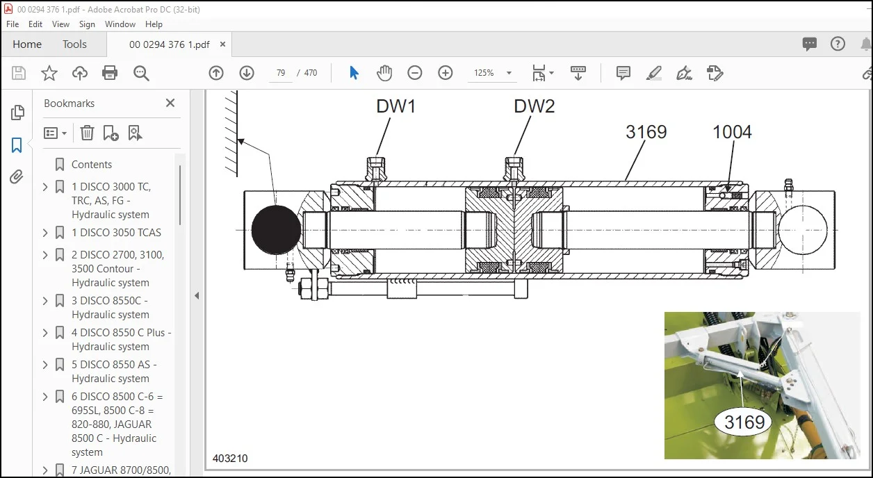
Working / transport position hydraulic cylinder (3169) 30
Description of function 30
4 DISCO 8550C – Hydraulic system
Hydraulic circuit diagram 31
Circuit diagram 32
Key to diagram 32
5 DISCO 8550 C Plus – Hydraulic system
Hydraulic circuit diagram 35
Circuit diagram 36
Key to diagram 36
6 DISCO 8550 AS – Hydraulic system
Overall circuit diagram 39
Raise/lower mower units and swath displacers hydraulic circuit diagram 40
Designations 41
Swath displacers hydraulic circuit diagram (belt drive) 42
Designations 43
Functions of overall hydraulic system 45
Raise mower units, raise swathers 46
Lowering the mower units, lowering the swather 48
Swath displacer 50
Position of components 54
Figures 54
7 DISCO 8500 C-6 = 695SL, 8500 C-8 = 820-880, JAGUAR 8500 C – Hydraulic system
Overall circuit diagram 57
Circuit diagram (DIN A3) 58
Key to diagram 59
4 000 294 376 1 – SYSEHD DISCO CORTO VOLTO LINER – 10/07
18204
Position of components 61
Description of function 62
8 JAGUAR 8700/8500, DISCO 8700 Plus – Hydraulic system
Overall circuit diagram 67
Circuit diagram (DIN A3) 68
Key to diagram 69
9 DISCO 8700 Plus, DISCO 8550 C-8 for JAGUAR 880-820 (491) – Hydraulic system
Overall circuit diagram 71
Circuit diagram (DIN A3) 72
Key to diagram 73
10 DISCO 3100 Contour / 2700C Contour
Hydraulic circuit diagram 75
Circuit diagram 76
Key to diagram 77
Description of function 78
Working / transport position hydraulic cylinder (3169) 79
Description of function 79
One-way restrictor valve, one-sided 80
Key to diagram 80
11 DISCO 3100C
Hydraulic circuit diagram 83
Circuit diagram 84
Key to diagram 85
Description of function 86
Working / transport position hydraulic cylinder (3169) 87
Description of function 87
One-way restrictor valve, one-sided 88
Key to diagram 88
89
12 DISCO 3900
Hydraulic circuit diagram 91
Circuit diagram 92
Key to diagram 93
Description of function 93
Working / transport position hydraulic cylinder (3169) 96
Description of function 96
One-way restrictor valve, one-sided 97
Key to diagram 97
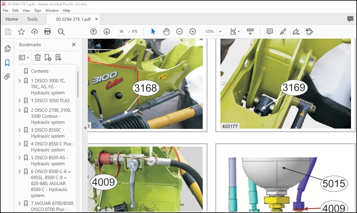
Position of components 98
13 CORTO 8100F – Hydraulic system
Overall circuit diagram 101
Circuit diagram (DIN A3) 102
Key to diagram 103
Description of function 104
000 294 376 1 – SYSEHD DISCO CORTO VOLTO LINER – 10/07 5
18204
14 CORTO 8100T – Hydraulic system
Overall circuit diagram 105
Circuit diagram (DIN A3) 106
Key to diagram 107
Description of function 108
15 VOLTO 52 T – Hydraulic system
Hydraulic circuit diagram up to serial no: 407 0 2422 109
Circuit diagram 110
Key to diagram 110
Hydraulic circuit diagram from serial no: 407 0 2423 113
Circuit diagram 114
Key to diagram 114
Windrowing rubber hydraulic circuit diagram 115
Circuit diagram 116
Key to diagram 116
Drawbar hydraulic cylinder (3154) 119
Graphics 120
Key to diagram 120
Description of function 120
16 VOLTO 640 H, VOLTO 64 H – Hydraulic system
Hydraulic circuit diagram 121
Circuit diagram 122
Key to diagram 122
17 VOLTO 770, 770 H – Hydraulic system
Hydraulic circuit diagram VOLTO 770 123
Circuit diagram 124
Key to diagram 124
Description of function 125
Flow divider (7069) 126
Key to diagram 127
Hydraulic circuit diagram VOLTO 770 H 129
Circuit diagram 130
Key to diagram 130
Description of function 131
Flow divider (7069) 132
Key to diagram 133
18 VOLTO 770 T – Hydraulic system
Hydraulic circuit diagram 135
Circuit diagram 136
Key to diagram 136
19 VOLTO 870 – Hydraulic system
Hydraulic circuit diagram up to serial no: 1225 139
Circuit diagram 140
Key to diagram 140
Hydraulic circuit diagram from serial no: 1226 143
6 000 294 376 1 – SYSEHD DISCO CORTO VOLTO LINER – 10/07
18204
Circuit diagram 144
Key to diagram 144
20 VOLTO 870 T – Hydraulic system
Hydraulic circuit diagram 147
Circuit diagram 148
Key to diagram 149
21 VOLTO 1050 – Hydraulic system
Hydraulic circuit diagram 151
Circuit diagram 152
Key to diagram 153
Description of function 153
22 VOLTO 1050 T – Hydraulic system
Hydraulic circuit diagram up to serial no: 6250 1537 155
Circuit diagram 156
Key to diagram 157
Description of function 158
Working position 160
Description of function 161
Transport position 162
Description of function 163
Hydraulic circuit diagram from serial no: 6250 1538 165
Circuit diagram 166
Key to diagram 167
Description of function 168
Working position 170
Description of function 171
Transport position 172
Description of function 173
23 VOLTO 1320 – Hydraulic system
Hydraulic circuit diagram 175
Circuit diagram 176
Key to diagram 177
Working position 178
Description of function 179
Transport position 180
Description of function 181
24 LINER 3000 – Hydraulic system
Hydraulic circuit diagram 183
Circuit diagram 184
Key to diagram 185
Description of function 187
Position of components 188
Key to diagram 188
Valve block I 191
Graphics 192
000 294 376 1 – SYSEHD DISCO CORTO VOLTO LINER – 10/07 7
18204
Key to diagram 193
Description of function 193
Valve block II 195
Graphics 196
Key to diagram 197
Description of function 197
Raise rear rotors solenoid valve (Y292) 199
Graphics 200
Key to diagram 201
Lock-up valve unit (7034) 203
Graphics 204
Description of function 205
25 LINER 3000 with Communicator – overall hydraulic system
Hydraulic circuit diagram – up to serial no 14 207
Circuit diagram (DIN A3) 208
Key to diagram 209
Description of function – Tractor hydraulic system port 211
Adjusting the rotor height 214
Key to diagram 214
Description of function 215
Hydraulic circuit diagram – from serial no 15 217
Circuit diagram (DIN A3) 218
Key to diagram 219
Description of function – Tractor hydraulic system port 221
Adjusting the rotor height 224
Key to diagram 224
Description of function 225
Valve block – up to serial no 14 227
Graphics 228
Key to diagram 229
Description of function – Tractor hydraulic system port 230
Valve block – from serial no 15 233
Graphics 234
Key to diagram 235
Input pressure balance up to serial no: 14 238
Graphics 238
Key to diagram 238
Description of function 238
Input pressure balance from serial no: 15 240
Graphics 240
Key to diagram 240
Description of function 240
Raising / lowering the front rotors 242
Graphics 242
Key to diagram 242
Description of function 243
Increasing / decreasing the working width 244
Graphics 244
8 000 294 376 1 – SYSEHD DISCO CORTO VOLTO LINER – 10/07
18204
Key to diagram 244
Description of function 245
Raising the rear rotors 246
Graphics 246
Key to diagram 246
Description of function 247
Raising / lowering the chassis 248
Graphics 248
Key to diagram 248
Description of function 249
Raising / lowering the rotors 250
Graphics 250
Key to diagram 250
Description of function 251
Flow divider 252
Graphics 252
Key to diagram 252
Description of function 253
Rotor hydraulic motor 254
Graphics 254
Key to diagram 254
Description of function 255
26 LINER 1550 Twin Profil – Hydraulic system
Hydraulic circuit diagram 257
Circuit diagram 258
Key to diagram 259
Description of function 260
27 LINER 1500 / 1550 – Hydraulic system
Hydraulic circuit diagram LINER 1500 263
Circuit diagram 264
Key to diagram 264
Description of function 265
Hydraulic circuit diagram LINER 1550 Profil 267
Circuit diagram 268
Key to diagram 268
Description of function 269
Flow divider (7069) 270
Key to diagram 271
28 LINER 1250 Profil – Hydraulic system
Hydraulic circuit diagram 273
Circuit diagram 274
Key to diagram 275
29 LINER 1250 Twin Profil – Hydraulic system
Hydraulic circuit diagram 277
Circuit diagram 278
Key to diagram 278
000 294 376 1 – SYSEHD DISCO CORTO VOLTO LINER – 10/07 9
18204
30 LINER 880 Profil – Hydraulic system
Hydraulic circuit diagram 281
Circuit diagram 282
Key to diagram 282
31 LINER 650 Twin / 650 Twin Profil – Hydraulic system
Hydraulic circuit diagram up to serial no: 407 0 2422 283
Circuit diagram 284
Key to diagram 284
Hydraulic circuit diagram from serial no: 407 0 2423 287
Circuit diagram 288
Key to diagram 288
Windrowing rubber hydraulic circuit diagram 289
Circuit diagram 290
Key to diagram 290
Drawbar hydraulic cylinder (3154) 293
Graphics 294
Key to diagram 294
Description of function 294
32 LINER 2800 / 2900 Basic machine
Hydraulic circuit diagram 295
Circuit diagram LINER 2800 / 2900 Basic machine 296
Key to diagram 297
Position of components 298
33 LINER 2800 / 2900 Basic machine with individual rotor lift
Hydraulic circuit diagram 301
Circuit diagram LINER 2800 / 2900 Basic machine with individual rotor lift 302
Key to diagram 303
Position of components 304
34 LINER 2700
Hydraulic circuit diagram 307
Circuit diagram 308
Key to diagram 308
Position of components 309
35 DISCO 8550C – Electric system
Electric circuit diagram 311
Circuit diagram 312
Key to diagram 313
36 DISCO 8550 C Plus – Electric system
Electric circuit diagram 315
Circuit diagram 316
Key to diagram 316
Connector/Socket 318
Connectors X1 through X4 in CCT (CLAAS Control Terminal) 318
Position of components 319
Figures 319
10 000 294 376 1 – SYSEHD DISCO CORTO VOLTO LINER – 10/07
18204
Speed monitor 320
Adjustment 320
Description of function 320
Malfunction 320
37 DISCO 8550 AS – Electric system
Swath displacers (belt drive) 323
Circuit diagram (DIN A3) 324
Key to diagram 325
Description of function 328
Adapting the belt speeds 330
Description of function 330
Menu „A“, left belt 333
Menu „B“, right belt 333
334
Menu „C“ 334
334
Menu „D“ 334
Position of components 335
Figures 335
38 DISCO 8500 C-6, 8500 C-8, JAGUAR 8500 C – Electric system
Overall circuit diagram 337
Circuit diagram (DIN A3) 338
Key to diagram 339
Description of function 341
Central terminal compartment 344
Graphics 344
Key to diagram 344
Central terminal compartment, starting in model year 2000 346
Graphics 346
Key to diagram 346
Central terminal compartment until model year 2000 348
Graphics 348
Key to diagram 348
Switch/pin assignment in CCT (CLAAS Control Terminal) 350
Graphics 350
Key to diagram 350
39 JAGUAR 8700/8500, DISCO 8700 Plus – Electric system
Overall circuit diagram from serial no 492 00 503 to 492 00 512 351
Circuit diagram (DIN A3) 352
Key to diagram 353
CCT pin assignment 355
MFG pin assignment 355
Block diagram 356
Position of components 357
000 294 376 1 – SYSEHD DISCO CORTO VOLTO LINER – 10/07 11
18204
40 JAGUAR 8700/8500, DISCO 8700 Plus – Electric system
Overall circuit diagram from serial no 492 00 513 359
Circuit diagram (DIN A3) 360
Key to diagram 361
CCT pin assignment 363
MFG pin assignment 363
Block diagram 364
Position of components 365
41 DISCO 8700 Plus, DISCO 8550 C-8 for JAGUAR 880-820 (491) – Electric system
Overall circuit diagram 367
Circuit diagram (DIN A3) 368
Key to diagram 369
CCT pin assignment 371
MFG pin assignment 371
Block diagram from serial no: 652 01278 and type 654, starting with model year 2002 372
Block diagram from serial no: 652 , 654 372
Position of components 373
Speed monitor 375
Graphics 375
Adjustment 376
Description of function 376
Malfunction 377
Speed monitor connector 377
42 CORTO 8100F – Electric system
Circuit diagram 379
Circuit diagram (DIN A3) 380
Key to diagram 381
Description of function 382
43 CORTO 8100T – Electric system
Circuit diagram 385
Circuit diagram (DIN A3) 386
Key to diagram 387
Description of function 387
44 LINER 3000 – Electric system
Electric circuit diagram 389
Circuit diagram (DIN A3) 390
Key to diagram 391
CCT CLAAS Control Terminal 393
Angular sensors 395
Adjusting the angular sensors 395
45 LINER 3000 with Communicator – Electric system
Structure of electric system documentation 397
Circuit diagram 397
Grid co-ordinates 398
Interconnection list 398
12 000 294 376 1 – SYSEHD DISCO CORTO VOLTO LINER – 10/07
18204
CLAAS standard: 399
Module A20 – CLAAS Control Unit (CCU) 401
Graphics (DIN A3) 402
Key to diagram 403
Pin assignment up to serial no: 605 0 2102 403
Pin assignment from serial no: 605 0 2103 405
Fuse 407
Circuit diagram – 01a Main power supply 409
Circuit diagram (DIN A 3) with installation kit „Basic tractor equipment“ (ISO socket) 410
Key to diagram 411
Description of function 411
Connector pin assignment 412
Circuit diagram – 01b Main power supply 413
Circuit diagram (DIN A 3) without installation kit „Basic tractor equipment“ (2-pin socket) 414
Key to diagram 415
Description of function 415
Connector pin assignment 416
Circuit diagram – 05 Terminal 417
Circuit diagram (DIN A3) 418
Key to diagram 419
Description of function 419
Connector pin assignment 419
Circuit diagram – 06a CAN Bus, Module power supply 421
Circuit diagram (DIN A 3) with installation kit „Basic tractor equipment“ (ISO socket) 422
Key to diagram 423
Description of function 423
Connector pin assignment 423
Circuit diagram – 06b CAN Bus, Module power supply 425
Circuit diagram (DIN A 3) without installation kit „Basic tractor equipment“ (2-pin socket) 426
Key to diagram 427
Description of function 427
Connector pin assignment 428
Circuit diagram – 07a Chassis, transport and working position 429
Circuit diagram (DIN A3) 430
Key to diagram 431
Measuring values table 431
Description of function 431
Connector pin assignment 432
Circuit diagram – 08a Turning area circuit 433
Circuit diagram (DIN A 3) with position measuring cylinder (up to serial no: 605 0 2102) 434
Key to diagram 435
Measuring values table 435
Description of function 436
Connector pin assignment 437
Circuit diagram – 08b Turning area circuit 439
Circuit diagram (DIN A 3) with angular sensors (from serial no: 605 0 2103) 440
Key to diagram 441
Measuring values table 441
000 294 376 1 – SYSEHD DISCO CORTO VOLTO LINER – 10/07 13
18204
Description of function 442
Connector pin assignment 443
Circuit diagram – 10a Raking height adjustment 445
Circuit diagram (DIN A3) 446
Key to diagram 447
Measuring values table 447
Description of function 448
Connector pin assignment 448
Circuit diagram – 11a Raise / lower rotor arms 449
Circuit diagram (DIN A3) 450
Key to diagram 451
Measuring values table 451
Description of function 452
Connector pin assignment 452
Circuit diagram – 13a Adjusting the working width of front rotors 453
Circuit diagram (DIN A3) 454
Key to diagram 455
Measuring values table 455
Description of function 455
Connector pin assignment 455
Circuit diagram – 26a Machine monitoring 457
Circuit diagram (DIN A3) 458
Key to diagram 459
Description of function 459
Connector pin assignment 459
IMAGES PREVIEW OF THE MANUAL:
Contact us: [email protected]
https://vimeo.com/721913544
PLEASE NOTE:
- This is not a physical manual but a digital manual – meaning no physical copy will be couriered to you. The manual can be yours in the next 2 mins as once you make the payment, you will be directed to the download page IMMEDIATELY.
- This is the same manual used by the dealers inorder to diagnose your vehicle of its faults.
- Require some other service manual or have any queries: please WRITE to us at [email protected]
S.M