CLAAS Perkins 1106C-E70TA and 1106D-E70TA Industrial Engines Disassembly and Assembly Manual – PDF DOWNLOAD
Original price was: $89.00.$24.95Current price is: $24.95.
CLAAS Perkins 1106C-E70TA and 1106D-E70TA Industrial Engines Disassembly and Assembly Manual – PDF DOWNLOAD
Description
CLAAS Perkins 1106C-E70TA and 1106D-E70TA Industrial Engines Disassembly and Assembly Manual – PDF DOWNLOAD
DESCRIPTION:
CLAAS Perkins 1106C-E70TA and 1106D-E70TA Industrial Engines Disassembly and Assembly Manual – PDF DOWNLOAD
Important Safety Information
- Most accidents that involve product operation, maintenance and repair are caused by failure to observe basic safety rules or precautions. An accident can often be avoided by recognizing potentially hazardous situations before an accident occurs. A person must be alert to potential hazards. This person should also have the necessary training, skills and tools to perform these functions properly.
- Improper operation, lubrication, maintenance or repair of this product can be dangerous and could result in injury or death.
- Do not operate or perform any lubrication, maintenance or repair on this product, until you have read and understood the operation, lubrication, maintenance and repair information.
- Safety precautions and warnings are provided in this manual and on the product. If these hazard warnings are not heeded, bodily injury or death could occur to you or to other persons.
- The hazards are identified by the “Safety Alert Symbol” and followed by a “Signal Word” such as “DANGER”, “WARNING” or “CAUTION”. The Safety Alert “WARNING” label is shown below
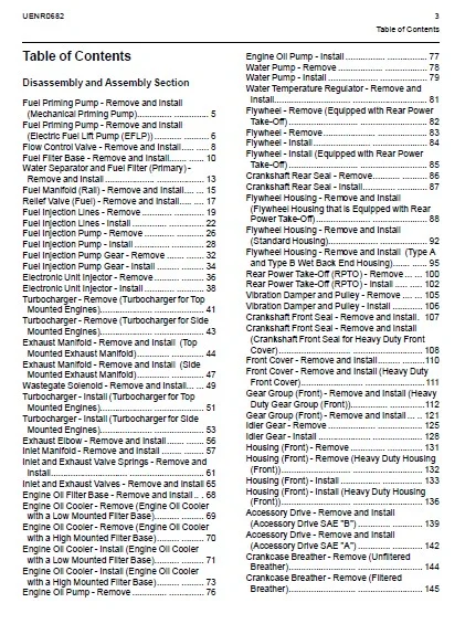
TABLE OF CONTENTS:
CLAAS Perkins 1106C-E70TA and 1106D-E70TA Industrial Engines Disassembly and Assembly Manual – PDF DOWNLOAD
Disassembly and Assembly Section
Fuel Priming Pump – Remove and Install
(Mechanical Priming Pump) 5
Fuel Priming Pump – Remove and Install
(Electric Fuel Lift Pump (EFLP)) 6
Flow Control Valve – Remove and Install 8
Fuel Filter Base – Remove and Install 10
Water Separator and Fuel Filter (Primary) –
Remove and Install 13
Fuel Manifold (Rail) – Remove and Install 15
Relief Valve (Fuel) – Remove and Install 17
Fuel Injection Lines – Remove 19
Fuel Injection Lines – Install 22
Fuel Injection Pump – Remove 26
Fuel Injection Pump – Install 28
Fuel Injection Pump Gear – Remove 32
Fuel Injection Pump Gear – Install 34
Electronic Unit Injector – Remove 36
Electronic Unit Injector – Install 38
Turbocharger – Remove (Turbocharger for Top
Mounted Engines) 41
Turbocharger – Remove (Turbocharger for Side
Mounted Engines) 43
Exhaust Manifold – Remove and Install (Top
Mounted Exhaust Manifold) 44
Exhaust Manifold – Remove and Install (Side
Mounted Exhaust Manifold) 47
Wastegate Solenoid – Remove and Install 49
Turbocharger – Install (Turbocharger for Top
Mounted Engines) 51
Turbocharger – Install (Turbocharger for Side
Mounted Engines) 53
Exhaust Elbow – Remove and Install 56
Inlet Manifold – Remove and Install 57
Inlet and Exhaust Valve Springs – Remove and
Install 61
Inlet and Exhaust Valves – Remove and Install 65
Engine Oil Filter Base – Remove and Install 68
Engine Oil Cooler – Remove (Engine Oil Cooler
with a Low Mounted Filter Base) 69
Engine Oil Cooler – Remove (Engine Oil Cooler
with a High Mounted Filter Base) 70
Engine Oil Cooler – Install (Engine Oil Cooler
with a Low Mounted Filter Base) 71
Engine Oil Cooler – Install (Engine Oil Cooler
with a High Mounted Filter Base) 73
Engine Oil Pump – Remove 76
Engine Oil Pump – Install 77
Water Pump – Remove 78
Water Pump – Install 79
Water Temperature Regulator – Remove and
Install 81
Flywheel – Remove (Equipped with Rear Power
Take-Off) 82
Flywheel – Remove 83
Flywheel – Install 84
Flywheel – Install (Equipped with Rear Power
Take-Off) 85
Crankshaft Rear Seal – Remove 86
Crankshaft Rear Seal – Install 87
Flywheel Housing – Remove and Install
(Flywheel Housing that is Equipped with Rear
Power Take-Off) 88
Flywheel Housing – Remove and Install
(Standard Housing) 92
Flywheel Housing – Remove and Install (Type A
and Type B Wet Back End Housing) 95
Rear Power Take-Off (RPTO) – Remove 100
Rear Power Take-Off (RPTO) – Install 102
Vibration Damper and Pulley – Remove 105
Vibration Damper and Pulley – Install 106
Crankshaft Front Seal – Remove and Install 107
Crankshaft Front Seal – Remove and Install
(Crankshaft Front Seal for Heavy Duty Front
Cover) 108
Front Cover – Remove and Install 110
Front Cover – Remove and Install (Heavy Duty
Front Cover) 111
Gear Group (Front) – Remove and Install (Heavy
Duty Gear Group (Front)) 112
Gear Group (Front) – Remove and Install 121
Idler Gear – Remove 125
Idler Gear – Install 128
Housing (Front) – Remove 131
Housing (Front) – Remove (Heavy Duty Housing
(Front)) 132
Housing (Front) – Install 133
Housing (Front) – Install (Heavy Duty Housing
(Front)) 136
Accessory Drive – Remove and Install
(Accessory Drive SAE “B”) 139
Accessory Drive – Remove and Install
(Accessory Drive SAE “A”) 142
Crankcase Breather – Remove (Unfiltered
Breather) 144
Crankcase Breather – Remove (Filtered
Breather) 145
Crankcase Breather – Install (Unfiltered
Breather) 146
Crankcase Breather – Install (Filtered
Breather) 146
Valve Mechanism Cover – Remove and
Install 148
Valve Mechanism Cover Base – Remove and
Install 150
Rocker Shaft and Pushrod – Remove 155
Rocker Shaft – Disassemble 157
Rocker Shaft – Assemble 158
Rocker Shaft and Pushrod – Install 159
Cylinder Head – Remove 162
Cylinder Head – Install 166
Lifter Group – Remove and Install 172
Camshaft – Remove and Install 174
Camshaft Gear – Remove and Install 175
Camshaft Bearings – Remove and Install 180
Engine Oil Pan – Remove (Aluminum Oil
Pan) 181
Engine Oil Pan – Install (Aluminum Oil Pan) 182
Piston Cooling Jets – Remove and Install 185
Pistons and Connecting Rods – Remove 187
Pistons and Connecting Rods – Disassemble 188
Pistons and Connecting Rods – Assemble 190
Pistons and Connecting Rods – Install 192
Connecting Rod Bearings – Remove (Connecting
rods in position) 193
Connecting Rod Bearings – Install (Connecting
rods in position) 194
Crankshaft Main Bearings – Remove and Install
(Crankshaft in Position) 196
Crankshaft – Remove 200
Crankshaft – Install 203
Crankshaft Timing Ring – Remove and Install 206
Crankshaft Gear – Remove and Install 207
Refrigerant Compressor – Remove and
Install 209
Bearing Clearance – Check 212
Coolant Temperature Sensor – Remove and
Install 213
Engine Oil Pressure Sensor – Remove and
Install 214
Camshaft Position Sensor – Remove and
Install 215
Crankshaft Position Sensor – Remove and
Install 216
Fuel Pressure Sensor – Remove and Install 217
Boost Pressure Sensor – Remove and Install 219
Inlet Air Temperature Sensor – Remove and
Install 220
Glow Plugs – Remove and Install 220
Alternator Belt – Remove and Install 222
Idler Pulley – Remove and Install (Grooved Idler
Pulley) 223
Idler Pulley – Remove and Install (Flat Idler
Pulley) 224
Belt Tensioner – Remove and Install 225
Fan – Remove and Install 227
Fan Drive – Remove and Install 228
ECM Mounting Bracket – Remove and Install 228
Electronic Control Module – Remove and
Install 231
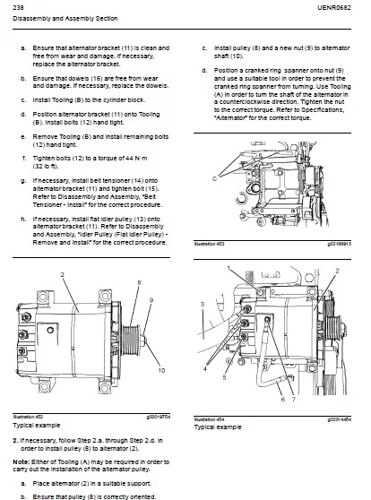
Alternator – Remove 233
Alternator – Install 235
Electric Starting Motor – Remove and Install 239
Air Compressor – Remove and Install (Twin
Cylinder Air Compressor) 240
Air Compressor – Remove and Install (Single
Cylinder Air Compressor) 246
Index Section
Index 253
4 UENR0682
IMAGES PREVIEW OF THE MANUAL:
CLAAS PERKINS 1106C-E70TA AND 1106D-E70TA INDUSTRIAL ENGINES DISASSEMBLY AND ASSEMBLY MANUAL – PDF DOWNLOAD:
PLEASE NOTE:
- This is not a physical manual but a digital manual – meaning no physical copy will be couriered to you. The manual can be yours in the next 2 mins as once you make the payment, you will be directed to the download page IMMEDIATELY.
- This is the same manual used by the dealers inorder to diagnose your vehicle of its faults.
- Require some other service manual or have any queries: please WRITE to us at [email protected]
S.M