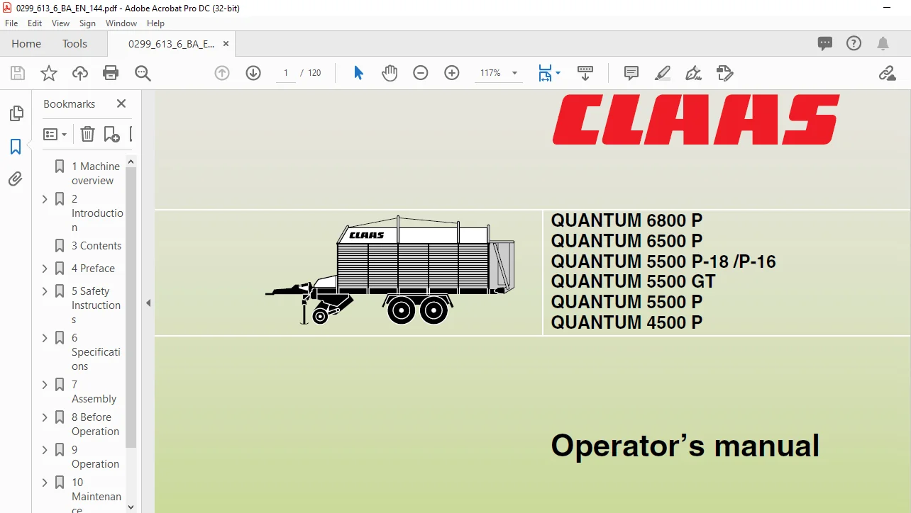
CLAAS QUANTUM 6800 P QUANTUM 6500 P QUANTUM 5500 P-18 /P-16 QUANTUM 5500 GT QUANTUM 5500 P QUANTUM 4500 P Operator’s Manual- PDF DOWNLOAD
Original price was: $78.00.$21.96Current price is: $21.96.
CLAAS QUANTUM 6800 P QUANTUM 6500 P QUANTUM 5500 P-18 /P-16 QUANTUM 5500 GT QUANTUM 5500 P QUANTUM 4500 P Operator’s Manual- PDF DOWNLOAD
Description
CLAAS QUANTUM 6800 P QUANTUM 6500 P QUANTUM 5500 P-18 /P-16 QUANTUM 5500 GT QUANTUM 5500 P QUANTUM 4500 P Operator’s Manual- PDF DOWNLOAD
DESCRIPTION:
CLAAS QUANTUM 6800 P QUANTUM 6500 P QUANTUM 5500 P-18 /P-16 QUANTUM 5500 GT QUANTUM 5500 P QUANTUM 4500 P Operator’s Manual- PDF DOWNLOAD
INTRODUCTION
- This manual provides information on the use, adjustment and servicing of the CLAAS self-loading forage wagon. Follow the advice on correct maintenance and servicing in order to ensure maximum performance and a long service life of your machine.
- Also, have assembly of your machine and regular inspections carried out by your specialist workshop. Failure to carry out maintenance work, or incorrect operation will result in poor machine efficiency and loss of valuable time.
- By ensuring correct operation, and carrying out maintenance and service work with care, you will be able to make full use of the technical knowledge and the experience with which your self-loading forage wagon has been designed.
GENERAL SAFETY AND ACCIDENT PREVENTION
INSTRUCTIONS
Basic Rule:
Check that the machine is roadworthy and safe to operate every time it is put into operation!
- Observe the current regulations regarding safety and accident prevention as well as the information in the operator’s manual.
- When using public roads observe all traffic regulations.
- Make yourself familiar with all equipment and controls and their functions before starting work as it will be too late once you have set off.
- Make sure that there is no one in close proximity to the machine before putting it into operation (especially children!). Check that visibility is good, particularly when reversing (have someone direct you if necessary).
- Clothing worn by the operator must be close-fitting. Avoid wearing loose jackets, shirts or ties!
- .Keep the machine clean to prevent fire.
- The machine must not be used to carry passengers.
- If it is necessary to access the machine, the PTO shaft and the tractor engine must be switched off. The ignition key of the tractor must be removed.
- The safety guards must be checked regularly for wear and replaced if necessary.
General
- Use only the recommended fastenings on the machine!
- Do not exceed the maximum support load on the trailer drawbar (the max. permissible hitched weight on the swinging drawbar).
- Use extreme caution when coupling and uncoupling the machine from the tractor to avoid risk of injury.
- Secure the machine against rolling away (parking brake, wheel chocks).
- A risk of injury due to crushing or shearing exists in the vicinity of the 3-point linkage!
- Couple the machine as specified by the instructions. Check the function of the trailer brake system. Observe the manufacturer’s instructions.
- Road performance, steering and braking are all influenced by the self-loading forage wagon and its load. Make sure that there is sufficient steering and braking capacity.
- Make sure no one is between the tractor and the self-loading forage wagon unless the vehicle is secured to prevent it from rolling away with the parking brake and/or wheel chocks.
- The ground speed must always be matched to the conditions. Avoid sudden curves when driving up or downhill or across a slope. Disengage the differential lock when turning. Never disengage the clutch and change gear when going downhill.
- Observe the maximum permissible axle loads and total weights!
- Operate the machine only when all guards are fitted and in the correct position!
- The crop guard is a safety device and should not be removed during operation.
- Ensure that all swivelling parts are secured during transport to prevent dangerous load shifting.
- . The independent brakes must not be used when towing the self-loading forage wagon (lock the pedals).
- With single-axle machines make sure that they do not tip when coupling and uncoupling because of an unevenly distributed load. Sufficient support is required.
- Loaded single-axle machines must not be transported on the support wheel.
- With single-axle machines make sure that the front axle of the tractor is not raised and the steering impaired by the drawbar load. Ensure that the tractor has the approved drawbar load.
- The drawbar height for drawbars with drawbar support must be adjusted by a suitable specialist workshop.
- . Ensure that the machine is stable when parked.
- Risk of injury by crushing or shearing when operating support equipment.
- All equipment must be placed in transport position before driving on the road. Lock the hydraulically operated articulated drawbar.
- Do not stand on the floor conveyor unless the PTO shaft and tractor engine are switched off. 5.3 BA QUANTUM 6800 P / 6500 P / 5500 P-18 / 5500 P-16 / 5500 GT / 5500 P / 4500 P – 299 613.6 Safety Instructions
- Feed and discharge components, such as pick-up, conveyors, metering equipment and discharge rollers, cannot be made completely safe by design because of their function; therefore it is imperative to remain a safe distance from these moving parts while the machine is operating. These instructions also apply for all other auxiliary equipment.
- Do not stand near the discharge area.
- There are dangerous implements under the safety devices that may continue to run after the drive has been switched off. Keep well clear of these devices until they have stopped.
- Always switch off the drive and the engine before carrying out troubleshooting, and for repair, maintenance and cleaning work. Remove the tractor ignition key.
- When working under raised covers make sure that they are sufficiently supported.
- When working with sharp-edged parts such as cutting knives always wear appropriate safety gear (gloves, shoes, etc.).
- Wear safety goggles when sharpening knives.
- Do not stand near hinged covers. 31. Leave safety guards in position and always place them in safe position.
TABLE OF CONTENTS:
CLAAS QUANTUM 6800 P QUANTUM 6500 P QUANTUM 5500 P-18 /P-16 QUANTUM 5500 GT QUANTUM 5500 P QUANTUM 4500 P Operator’s Manual- PDF DOWNLOAD
1 Machine overview 11
2 Introduction
Introduction 21
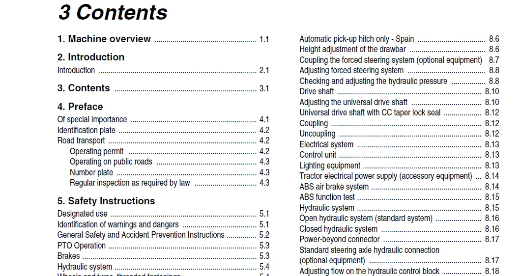
3 Contents 31
4 Preface
Of special importance 41
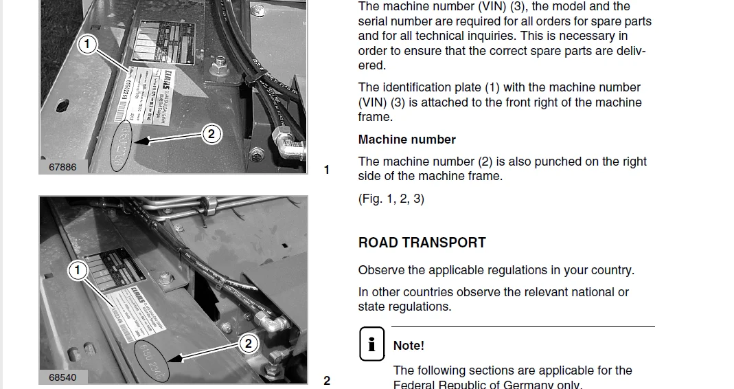
Identification plate 42
Road transport 42
Operating permit 42
Operating on public roads 43
Number plate 43
Regular inspection as required by law 43
5 Safety Instructions
Designated use 51
Identification of warnings and dangers 51
General Safety and Accident Prevention Instructions 52
PTO Operation 53
Brakes 53
Hydraulic system 54
Wheels and tyres, threaded fastenings 54
Maintenance 54
Sound pressure level 54
Safety decals with warning symbols 55
6 Specifications
QUANTUM 6800 P 61
QUANTUM 5500 P-18 61
QUANTUM 6500 P 61
QUANTUM 5500 GT / 5500 P-16 63
QUANTUM 5500 P 63
QUANTUM 4500 P 63
7 Assembly
Assembly 71
QUANTUM 6800 P / 5500 P-18 to 615 0 2366 71
QUANTUM 6500 P (Spain only) 73
QUANTUM 5500 P-16 / 5500 GT / 5500 P to 615 0 2366 75
QUANTUM 4500 P to 615 0 2366 76
QUANTUM 6800 P / 5500 P-18 from 615 0 2367 77
QUANTUM 5500 P-16 / 5500 P from 615 0 2367 710
Metal top (optional equipment) from 615 0 2367 712
Coupling machine for the first time 712
8 Before Operation
Check and observe the following before operation 81
Coupling to the tractor 83
Hydraulic articulated drawbar 83
QUANTUM 6800 P / 5500 P-18 83
QUANTUM 6500 P / 5500 P-16 / 5500 GT / 5500 P /
4500 P 83
Ring hitches 84
Hydraulic articulated drawbar – automatic pick-up hitch 85
Automatic pick-up hitch only – Spain 86
Height adjustment of the drawbar 86
Coupling the forced steering system (optional equipment) 87
Adjusting forced steering system 88
Checking and adjusting the hydraulic pressure 88
Drive shaft 810
Adjusting the universal drive shaft 810
Universal drive shaft with CC taper lock seal 812
Coupling 812
Uncoupling 812
Electrical system 813
Control unit 813
Lighting equipment 813
Tractor electrical power supply (accessory equipment) 814
ABS air brake system 814
ABS function test 815
Hydraulic system 815
Open hydraulic system (standard system) 816
Closed hydraulic system 816
Power-beyond connector 817
Standard steering axle hydraulic connection
(optional equipment) 817
Adjusting flow on the hydraulic control block 818
Support foot 818
After attaching the self-loading forage wagon 818
Parking the self-loading forage wagon 819
Air brake system 819
Two-line system 819
Towing with tractors without
air brake system 820
Hydraulically operated brake system 820
Parking brake 821
Setting brake 821
Releasing brake 821
Wheel chocks 821
Inspection hatch 822
Unhitching 823
Self-loading forage wagon with air brake system 825
Self-loading forage wagon with hydraulically
operated brake 825
Self-loading forage wagon with ABS air brake system 825
Prior to transportation 826
Driving on public roads 826
9 Operation
Short instructions 91
Loading operation 91
Unloading operation 91
Articulated drawbar 91
Indicator lights 92
2-speed motor (optional equipment) 92
Loading operation 93
Lowering and lifting the pick-up 93
Preselecting the working height of the pick-up 93
Roll-type crop guard (QUANTUM 6800 P / 5500 P-18) 94
Contents
32 BA QUANTUM 6800 P / 6500 P / 5500 P-18 / 5500 P-16 / 5500 GT / 5500 P / 4500 P – 299 6136
Contents
Baffle plate (QUANTUM 6500 P / 5500 P-16 / 5500 GT /
5500 P / 4500 P) 95
Opening knife frame hydraulically 95
Engaging floor conveyor – filling load space 96
Unloading operation 97
Open tailgate 97
Unloading the load space 97
Floor conveyor 2-speed motor (optional equipment) 98
Close tailgate 98
Loading space lighting
(Quantum 6800 P / 5500 P-18 only) 99
Operation of self-loading forage wagon 99
Loading operation (general) 910
Driving on public roads 910
After use 910
Standard steering axle (optional equipment) 911
Locking the standard steering axle 911
Unlocking the standard steering axle 912
Drawbar extension for automatic pick-up hitch
M01 0010 (optional equipment) 912
Hydraulic drawbar damping
(QUANTUM 6800 P / 6500 P / 5500 P-18) 913
Activate drawbar damping 913
Emergency control 914
10 Maintenance
Important Maintenance Instructions 101
Wheels / tyres 101
Brakes and axles 101
Compressed-air actuated brakes 101
Hydraulic system 101
Chassis 102
Chains 102
Bolts 102
Lubrication 102
Guards 102
Brakes and axles 103
Air brake system 103
ABS air brake system 103
Draining compressed air reservoir 104
Air pipe filter 104
Cleaning the filter element 104
Components of the air cleaner 104
Adjusting the brake – checking the brake cylinder
piston stroke 105
Brake regulator 105
Brake linings 105
Forced steering system 105
Refilling and bleeding the forced steering system 106
Bleeding steering cylinder 107
Bleeding master cylinder 108
Adjusting stroke of master cylinder 109
Extending master cylinder 109
Retracting master cylinder 1010
Setting operating pressure for forced steering system 1010
Cutting mechanism 1010
Changing the cutting knives 1010
Knife removal 1011
Knife installation 1011
Adjusting the scraper unit 1012
Drive systems 1013
Main gearbox 1013
Floor conveyor gearbox 1013
Floor conveyor drive with 2-speed motor 1014
Rotor drive 1014
Chains 1015
Tensioning the drive chains 1015
Tensioning pick-up drive chain 1016
Floor conveyor chains 1016
Air bounce 1016
Lifting and lowering device for air-cushioned axles 1017
Electrical system 1018
Adjusting the reed switches 1018
Hydraulic system 1019
Changing pressure filter 1019
Accumulator
(QUANTUM 6800 P / 6500 P / 5500 P-18 only) 1020
Hydraulic hose connections 1021
Gas shock absorber 1022
Maintenance and lubrication holes 1023
Drive shaft 1023
Clutch 1024
Cam-type cut-out clutch 1024
Tyres: 1025
Guards 1025
Screw connections 1025
Fasteners 1026
End of season storage 1026
Lubrication chart 1026
11 Lubrication Chart
Safety Instructions 111
Lubricants 111
Lubrication 112
IMAGES PREVIEW OF THE MANUAL:
CLAAS QUANTUM 6800 P QUANTUM 6500 P QUANTUM 5500 P-18 /P-16 QUANTUM 5500 GT QUANTUM 5500 P QUANTUM 4500 P OPERATOR’S MANUAL- PDF DOWNLOAD:
PLEASE NOTE:
- This is the SAME MANUAL used by the dealerships to diagnose your vehicle
- No waiting for couriers / posts as this is a PDF manual and you can download it within 2 minutes time once you make the payment.
- Your payment is all safe and the delivery of the manual is INSTANT – You will be taken to the DOWNLOAD PAGE.
- So have no hesitations whatsoever and write to us about any queries you may have : heydownloadss @gmail.com
S.M