CLAAS ROLLANT 250 ROTO CUT Service Manual PDF Download
Original price was: $67.00.$24.95Current price is: $24.95.
CLAAS ROLLANT 250 ROLLANT 250 ROTO CUT Repair manual – PDF DOWNLOAD
Description
CLAAS ROLLANT 250 ROLLANT 250 ROTO CUT Repair manual – PDF DOWNLOAD
DESCRIPTION:
CLAAS ROLLANT 250 ROLLANT 250 ROTO CUT Repair manual – PDF DOWNLOAD
GENERAL
Introduction
- This CLAAS REPAIR MANUAL is to assist in preserving the permanent working order and therefore the high value of your CLAAS round baler by careful maintenance and service. Experience gathered by both our service engineers and factory staff
- has been compiled in this REPAIR MANUAL. The figures explain the procedure of repairs and the text describes the different adjustments to be made, the use of CLAAS special tools etc. The illustrations included in support to the
- explanations show the sequence of major repairs so that minor repairs can easily be followed. The CLAAS REPAIR MANUAL is filed in a folder which allows to insert supplementary pages as issued following technical developments and to always
- have an updated manual at hand for reference. To be sure, always compare settings and filling capacities with specifications stated in the current Operator’s Manual which applies to the machine.
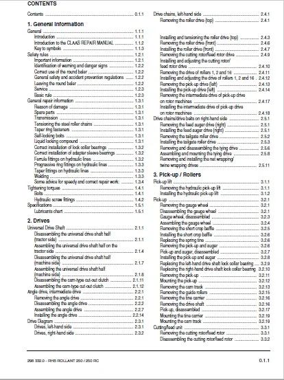
TABLE OF CONTENTS:
CLAAS ROLLANT 250 ROLLANT 250 ROTO CUT Repair manual – PDF DOWNLOAD
Contents 011
1 General information
General 111
Introduction 111
Introduction to the CLAAS REPAIR MANUAL 112
Key to symbols 113
Safety rules 121
Important information 121
Identification of warning and danger signs 122
Correct use of the round baler 122
General safety and accident prevention regulations 122
Leaving the round baler 122
Service 123
Basic rule 123
General repair information 131
Reason of damage 131
Spare parts 131
Transmission 131
Tensioning the steel roller chains 131
Taper ring fasteners 131
Self-locking bolts 131
Liquid locking compound 131
Correct installation of lock collar bearings 132
Correct installation of adapter sleeve bearings 132
Ferrule fittings on hydraulic lines 132
Progressive ring fittings on hydraulic lines 133
Taper fittings on hydraulic lines 133
Welding 133
Some advice for speedy and correct repair work: 134
Tightening torques 141
Bolts 141
Hydraulic screw fittings 142
Specifications 151
Lubricants chart 151
2 Drives
Universal Drive Shaft 211
Disassembling the universal drive shaft half
(tractor side) 211
Assembling the universal drive shaft half on the
tractor side 214
Disassembling the universal drive shaft half
(machine side) 217
Assembling the universal drive shaft half
(machine side) 218
Disassembling the cam-type cut-out clutch 2111
Assembling the cam-type cut-out clutch 2112
Angle drive, intermediate drive 221
Removing the angle drive 221
Disassembling the angle drive 222
Assembling the angle drive 227
Installing the angle drive 2214
Drive Diagram 231
Drives, left-hand side 231
Drives, right-hand side 232
Drive chains, left-hand side 241
Removing the roller drive (top) 241
Installing and tensioning the roller drive (top) 243
Removing the roller drive (front) 246
Installing the roller drive (front) 247
Removing the cutting rotor/feed rotor drive 249
Installing and adjusting the cutting rotor/
feed rotor drive 2410
Removing the drive of rollers 1, 2 and 16 2411
Installing and adjusting the drive of rollers 1, 2 and 16 2412
Removing the pick-up drive (left) 2413
Installing the pick-up drive (left) 2414
Removing the intermediate drive of pick-up drive
on rotor machines 2417
Installing the intermediate drive of pick-up drive
on rotor machines 2418
Drive chains/drive belts on right-hand side 251
Removing the feed auger drive (right) 251
Installing the feed auger drive (right) 251
Removing the tailgate roller drive 252
Installing the tailgate roller drive 253
Removing and disassembling the tying drive 256
Assembling and mounting the tying drive 258
Removing and installing the net wrapping/
twine wrapping drives 2511
3 Pick-up / Rollers
Pick-up lift 311
Removing the hydraulic pick-up lift 311
Installing the hydraulic pick-up lift 312
Pick-up 321
Removing the gauge wheel 321
Disassembling the gauge wheel 321
Gauge wheel, disassembled 323
Assembling the gauge wheel 324
Removing the short crop baffle 325
Installing the short crop baffle 326
Replacing the spring tine 326
Removing the pick-up and auger 326
Pick-up and auger, disassembled 327
Installing the pick-up and auger 328
Replacing the left-hand drive shaft lock collar bearing 329
Replacing the right-hand drive shaft lock collar bearing 3210
Removing the pick-up 3211
Mounting the pick-up 3212
Removing the cam track 3213
Removing the guide rollers 3215
Removing the tine carrier 3216
Removing the drive shaft 3216
Pick-up, disassembled 3217
Mounting the tine carrier 3219
Mounting the cam track 3219
Cutting/feed unit 331
Removing the cutting rotor/feed rotor 331
Disassembling the cutting rotor/feed rotor 332
012 RHB ROLLANT 250 / 250 RC – 298 3320
Contents
Cutting rotor/feed rotor, disassembled 334
Assembling the cutting rotor/feed rotor 335
Installing the cutting rotor/feed rotor 335
Removing the scraper of cutting rotor/feed rotor 338
Installing the scraper of cutting rotor/feed rotor 338
Removing the knife shaft 339
Knife shaft, disassembled 3311
Installing the knife shaft 3312
Rollers 341
Removing roller 3 341
Roller 3, disassembled 345
Installing roller 3 346
Removing roller 11 349
Remove tailgate 349
Roller 11, disassembled 3411
Installing roller 11 3412
Swinging segment 351
Removing the swinging segment 351
Disassembling the swinging segment 352
Assembling the swinging segment 354
Installing the swinging segment 359
Removing the hydraulic backwinder 361
Hydraulic backwinder, disassembled 362
Mounting the hydraulic backwinder 363
Replacing the mechanical backwinder 367
4 Twine and net wrapping
Twine Wrapping 411
Removing the twine wrapping unit 411
Removing the cutting unit 412
Removing the deflector 413
Disassembling the twine wrapping unit 413
Disassembling the cutting unit 416
Assembling the cutting unit 4113
Assembling the twine wrapping unit 4114
Installing the deflector 4119
Installing the cutting unit 4121
Mounting the twine wrapping unit 4123
Net wrapping 421
Removing the net wrapping unit 421
Disassembling the net wrapping unit 423
Assembling the net wrapping unit 4213
Mounting the net wrapping unit 4220
5 Machine housing
Tailgate 511
Removing the tailgate 511
Mounting the tailgate 513
6 Hydraulic system – Electric system
Valve combination 611
Checking the tightness of tailgate valve combination and
hydraulic cylinder 611
Removing the valve combination 612
Disassembling the valve combination 613
Valve combination, disassembled 614
Assembling the valve combination 615
Removing the 4/3-way valve with circulation
shut-off valve 616
Disassembling the 4/3-way valve with circulation
shut-off valve 616
Assembling the 4/3-way valve with circulation
shut-off valve 617
Mounting the 4/3-way valve with circulation
shut-off valve 618
Removing the NG2 solenoid valve 619
Disassembling the NG2 solenoid valve 619
NG 2 solenoid valve, disassembled 6111
Assembling the NG2 solenoid valve 6112
Mounting the NG2 solenoid valve 6114
Hydraulic cylinders 621
Removing and installing the hydraulic cylinders 621
Disassembling the hydraulic cylinders 622
Assembling the hydraulic cylinders 624
Disassembling the hydraulic cylinder (knife lift) 626
Assembling the hydraulic cylinder (knife lift) 626
7 Index
IMAGES PREVIEW OF THE MANUAL:
CLAAS ROLLANT 250 ROLLANT 250 ROTO CUT REPAIR MANUAL – PDF DOWNLOAD:
PLEASE NOTE:
- This is the SAME exact manual used by your dealers to fix your vehicle.
- The same can be yours in the next 2-3 mins as you will be directed to the download page immediately after paying for the manual.
- Any queries / doubts regarding your purchase, please feel free to contact [email protected]
S.M