CLAAS RU 450 Service Repair Manual PDF Download
Original price was: $78.00.$24.95Current price is: $24.95.
CLAAS RU 450 REPAIR HANDBOOK Manual – PDF DOWNLOAD
Description
CLAAS RU 450 REPAIR HANDBOOK Manual – PDF DOWNLOAD
DESCRIPTION:
CLAAS RU 450 REPAIR HANDBOOK Manual – PDF DOWNLOAD
General information
INTRODUCTION
- This CLAAS repair manual is to help maintain continuous operation and thus the high value CLAAS corn picker attachments through careful maintenance and service-related inspection.
- The knowledge of our service technicians and factory experience is brought together in this Repair Manual.
- The order of the pictures show the repair process while the text contains important information for adjustments, about how to use special tools from CLAAS, and additional similar information.
- The important repairs are shown in a way so that even individual or small tasks can be seen and easily followed. The manual will be expanded to include further technical developments of the machines using supplements to be used as a reference which is always up-to-date. Always compare the settings and filling amounts with the current operation manual of the respective machine
INTRODUCTION TO THE CLAAS REPAIR MANUAL
- The chapters of the CLAAS Repair Manual correspond to the order of the CLAAS spare part list. The pictures and pages in each chapter begin with one and are numbered consecutively.
- The numbering at the bottom of each page is made up of the first number of the main group and the page number which follows the period.
- Those assembly processes which only apply to certain machine types are marked with type-related details while the assembly processes that apply to all of the machine types dealt with in this manual remain neutral.
- The order of the entries is given using an additional number which is shown using a dash after the page number. Entries received later are fixed to the respective main group and the respective Table of Contents is exchanged. The picture references are used as a quick orientation for recurring assembly processes.
- The explanation of the picture references is at the beginning of the manual. Informative explanations are at the beginning of the manual under the heading ”General repair information” Please read and follow this information. The information is the basis for a safe and lasting operation after a repair has been made
GENERAL INFORMATION FOR REPAIRS
1. Determine what was responsible for the damage, define the damage claim, and secure the machine.
2. Use original CLAAS spare parts and the respective CLAAS special tool.
3. When dismantling the gearbox, first drain the oil and then remove the gearbox. Separate the parts which are fit into one another with a soft metal or plastic hammer.
4. Adjusting the roller chain tension:
Steel roller chains have the correct tension when you can push with your thumb in the middle of the roller chain between the axles and approx. 2% of play results. Test the stretching or new chains more frequently. Example: Distance between axle 500 mm = Approx. 10 mm of displacement.
5. Tapered ring connections:
Tapered ring connections are a secure connection also during the transfer of power from the drive mechanism to the shaft and the other way around during Disassembly: After loosening the axial, loosen the tapered ring connections with a powerful blow using a stroke pipe. ATTENTION! The inner diameter of the stroke pipe must be wide enough to grip over the tapered ring. Assembly: It is important during the assembly that the shaft, hub, flat keys, and tapered rings are thoroughly cleaned, treated with semi-fluid lubricant NLGI Class 00 (Shell Retinax G, for example), and tightened with the stated torque in the correct order of assembly.
TABLE OF CONTENTS:
CLAAS RU 450 REPAIR HANDBOOK Manual – PDF DOWNLOAD
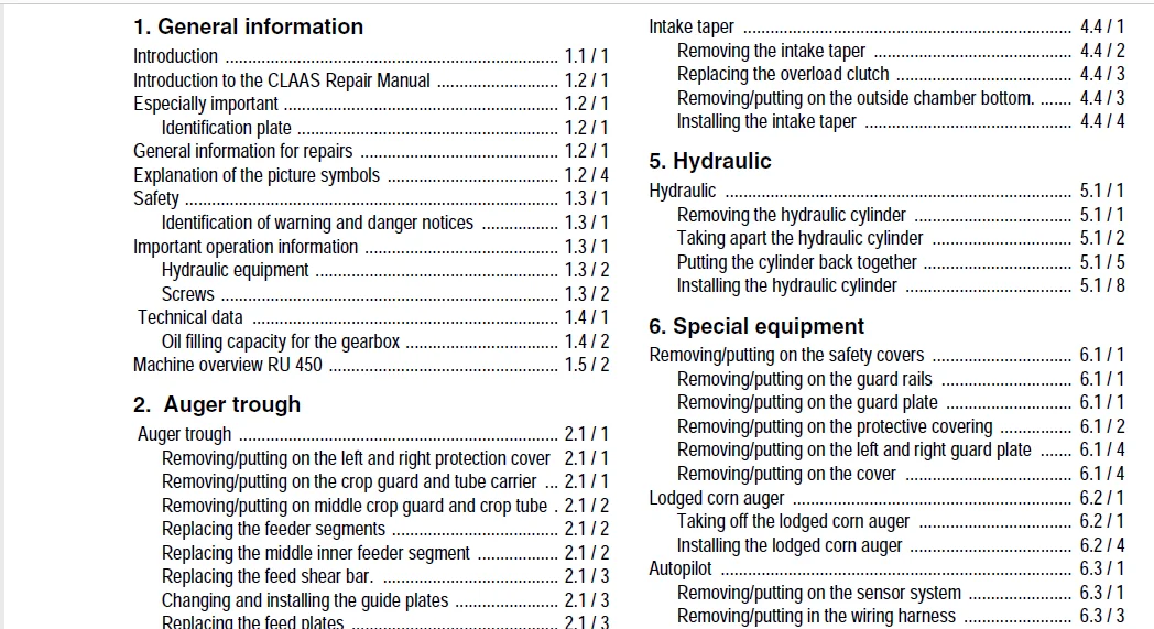
1 General information
Introduction 11 / 1
Introduction to the CLAAS Repair Manual 12 / 1
Especially important 12 / 1
Identification plate 12 / 1
General information for repairs 12 / 1
Explanation of the picture symbols 12 / 4
Safety 13 / 1
Identification of warning and danger notices 13 / 1
Important operation information 13 / 1
Hydraulic equipment 13 / 2
Screws 13 / 2
Technical data 14 / 1
Oil filling capacity for the gearbox 14 / 2
Machine overview RU 450 15 / 2
2 Auger trough
Auger trough 21 / 1
Removing/putting on the left and right protection cover 21 / 1
Removing/putting on the crop guard and tube carrier 21 / 1
Removing/putting on middle crop guard and crop tube 21 / 2
Replacing the feeder segments 21 / 2
Replacing the middle inner feeder segment 21 / 2
Replacing the feed shear bar 21 / 3
Changing and installing the guide plates 21 / 3
Replacing the feed plates 21 / 3
Replacing the scrapers 21 / 5
3 Machine frame
Removing/putting on the lock 31 / 1
Removing/putting on left and right side of the supporting arm
31 / 2
Installing the rotor transmission 31 / 4
Putting in the angular transmission with the tapered clutch
31 / 6
Replacing the tapered clutch 31 / 7
Removing the supporting arm 31 / 9
Installing the supporting arm 31 / 11
4 Knife/Feed
Intermediate points 41 / 1
Removing/installing the intermediate points 41 / 1
Removing/installing the support to the intermediate points
41 / 1
Removing/putting on the sliding skid 41 / 1
Removing/putting on the position transmitter 41 / 2
Removing/putting on the divider points 41 / 2
Removing/putting on the outer points 41 / 3
Removing/installing the intake plates 42 / 1
Removing/installing the left or right intake plates 42 / 1
Removing/putting on the upper intake plates 42 / 7
Removing/putting on the bottom intake plates 42 / 8
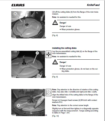
Removing/installing the cutting disks 43 / 1
Replacing the knife on the cutting disks 43 / 1
Removing the cutting disks 43 / 2
Installing the cutting disks 43 / 3
Intake taper 44 / 1
Removing the intake taper 44 / 2
Replacing the overload clutch 44 / 3
Removing/putting on the outside chamber bottom 44 / 3
Installing the intake taper 44 / 4
5 Hydraulic
Hydraulic 51 / 1
Removing the hydraulic cylinder 51 / 1
Taking apart the hydraulic cylinder 51 / 2
Putting the cylinder back together 51 / 5
Installing the hydraulic cylinder 51 / 8
6 Special equipment
Removing/putting on the safety covers 61 / 1
Removing/putting on the guard rails 61 / 1
Removing/putting on the guard plate 61 / 1
Removing/putting on the protective covering 61 / 2
Removing/putting on the left and right guard plate 61 / 4
Removing/putting on the cover 61 / 4
Lodged corn auger 62 / 1
Taking off the lodged corn auger 62 / 1
Installing the lodged corn auger 62 / 4
Autopilot 63 / 1
Removing/putting on the sensor system 63 / 1
Removing/putting in the wiring harness 63 / 3
7 Drives
Auger drive 71 / 1
Removing the auger drive 71 / 1
Removing/putting on the bearing housing 71 / 4
Removing the feeder auger 71 / 5
Putting in the feeder auger 71 / 7
Installing the auger drive 71 / 8
Replacing the comb feeders on the feeder trough 71 / 12
Replacing the reinforcement on the feeder trough 71 / 13
Knife drive 72 / 1
Removing/installing the entering transmission 72 / 1
Removing/installing the main transmission 72 / 2
Removing/installing the rotor transmission 72 / 6
Bevel drive 73 / 1
Removing/installing the bevel drive 73 / 1
Transmission 74 / 1
General – Important information 74 / 1
Main transmission (B) 75 / 1
Taking apart the main transmission 75 / 1
Putting together the main transmission 75 / 9
Main transmission – Shift transmission (H) 76 / 1
Main transmission – Taking apart the shift transmission (H)
76 / 1
Main transmission – Putting together the shift transmission
76 / 15
Bevel transmission 77 / 1
Taking apart/putting together the bevel transmission 77 / 1
Putting together the bevel transmission 77 / 8
Rotor transmission 78 / 1
Taking apart the rotor transmission 78 / 1
I / 2 RU 450 – 297 9250
Contens
Scraper transmission 79 / 1
Taking apart the scraper transmission 79 / 1
Putting together the scraper transmission 79 / 4
Angular transmission 710 / 1
Taking apart the angular transmission 710 / 1
8 Universal drive shaft / Clutches
Universal drive shaft / Clutches 81 / 1
Taking apart/Putting back together the tapered clutch 81 / 1
IMAGES PREVIEW OF THE MANUAL:
CLAAS RU 450 REPAIR HANDBOOK MANUAL – PDF DOWNLOAD:
PLEASE NOTE:
- This is the SAME manual used by the dealers to troubleshoot any faults in your vehicle. This can be yours in 2 minutes after the payment is made.
- Contact us at [email protected] should you have any queries before your purchase or that you need any other service / repair / parts operators manual.
S.M