Claas Scorpion 6030 Compact Model: 408-01 Repair Manual – PDF DOWNLOAD
Original price was: $89.00.$26.95Current price is: $26.95.
Claas Scorpion 6030 Compact Model: 408-01 Repair Manual – PDF DOWNLOAD
Description
Claas Scorpion 6030 Compact Model: 408-01 Repair Manual – PDF DOWNLOAD
DESCRIPTION:
Claas Scorpion 6030 Compact Model: 408-01 Repair Manual – PDF DOWNLOAD
Notes on the repair manual
This manual contains important information on how to service your machine safely, correctly and economically. Therefore, it aims not only at new personnel, but it also serves as a reference for experienced ones. It helps to avoid dangerous situations and reduce repair costs and downtimes. Furthermore, the reliability and the service life of the machine will be increased by following the instructions in the Operator’s Manual. Careful and prudent working is the best way to avoid accidents! Insist on using original spare parts when performing maintenance and repair work. This ensures operational safety and readiness of your machine, and maintains its value. Please contact your dealer if you require more information on the machine.
Notice!
Repair work, maintenance or modifications may be performed only by specifically trained technical personnel or by a workshop!
Insist on using original spare parts for repairs.
The machine’s permits, certifications, registrations, etc., may be withdrawn if machine parts/components with a prescribed condition or quality, or machine parts/components that can put persons at risk during operation, are subsequently modified or exchanged.
TABLE OF CONTENTS:
Claas Scorpion 6030 Compact Model: 408-01 Repair Manual – PDF DOWNLOAD
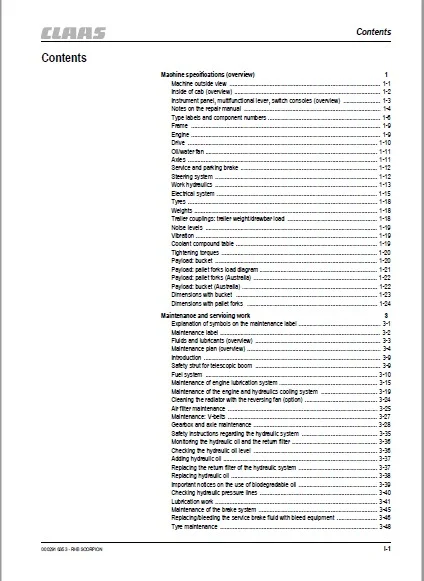
Contents
Machine specifications (overview) 1
Machine outside view 1-1
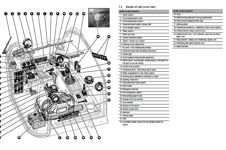
Inside of cab (overview) 1-2
Instrument panel, multifunctional lever, switch consoles (overview) 1-3
Notes on the repair manual 1-4
Type labels and component numbers 1-6
Frame 1-9
Engine 1-9
Drive 1-10
Oil/water fan 1-11
Axles 1-11
Service and parking brake 1-12
Steering system 1-12
Work hydraulics 1-13
Electrical system 1-15
Tyres 1-18
Weights 1-18
Trailer couplings: trailer weight/drawbar load 1-18
Noise levels 1-19
Vibration 1-19
Coolant compound table 1-19
Tightening torques 1-20
Payload: bucket 1-20
Payload: pallet forks load diagram 1-21
Payload: pallet forks (Australia) 1-22
Payload: bucket (Australia) 1-22
Dimensions with bucket 1-23
Dimensions with pallet forks 1-24
Maintenance and servicing work 3
Explanation of symbols on the maintenance label 3-1
Maintenance label 3-2
Fluids and lubricants (overview) 3-3
Maintenance plan (overview) 3-4
Introduction 3-9
Safety strut for telescopic boom 3-9
Fuel system 3-10
Maintenance of engine lubrication system 3-15
Maintenance of the engine and hydraulics cooling system 3-19
Cleaning the radiator with the reversing fan (option) 3-24
Air filter maintenance 3-25
Maintenance: V-belts 3-27
Gearbox and axle maintenance 3-28
Safety instructions regarding the hydraulic system 3-35
Monitoring the hydraulic oil and the return filter 3-36
Checking the hydraulic oil level 3-36
Adding hydraulic oil 3-37
Replacing the return filter of the hydraulic system 3-37
Replacing hydraulic oil 3-38
Important notices on the use of biodegradable oil 3-39
Checking hydraulic pressure lines 3-40
Lubrication work 3-41
Maintenance of the brake system 3-45
Replacing/bleeding the service brake fluid with bleed equipment 3-46
Tyre maintenance 3-48
Contents
Contents
I-2 00 0291 635 3 – RHB SCORPION
Heating and ventilation maintenance 3-50
Air conditioning (option): maintenance 3-51
Maintenance of the electrical system 3-54
Maintenance of trailer coupling 3-57
General maintenance work on the machine 3-58
Cleaning inside the cab 3-59
Cleaning the seat belt 3-59
Cleaning the exterior of the machine 3-59
Checking screw connections 3-59
Checking pivots and hinges 3-59
Cleaning the engine compartment 3-60
Maintenance and servicing work “Aggressive Media” 3-61
Maintenance and servicing of attachments on the quickhitch 3-63
Engine/radiator/diagnosis 4
Electrical system/hydraulics – fan (electrical diagram) 4-1
Diesel engine electrical system diagram 4-7
Diagnosis diagram 4-13
Manual throttle diagram 4-17
Overview of electric engine speed lock (accelerator pedal lock) 4-20
Engine/drive coupler (overview) 4-21
Fuel system (88/103 kW) (overview) 4-22
Fuel system 4-23
Bleeding the fuel system 4-24
Fuel specification 4-25
Coolant specification 4-25
Diesel engine TD 2011 L04 W overview 4-26
Electrical components on engine (overview) 4-27
Water circuit: water pump, thermostat 4-28
Switching off minus compensation 4-29
Heating connection 4-29
Engine trouble 4-30
Fan circuit 4-32
Overview of fan drive components 4-33
Valve block with/without reversing function 4-34
Setting the upper fan speed 4-35
Function: reversing fan operation 4-36
Drive 5
40 kph drive hydraulics diagram for model 408 5-1
20 kph drive hydraulics diagram for model 408 5-5
Model 408 drive electrics diagram 5-9
Towing and transporting the machine 5-11
Hydraulic pump H1 P078 (model 408) (40 kph) 5-13
High-speed gearbox (40 kph) 5-14
Gearbox overview (40 kph) 5-15
Overview of control cover and circuit diagram (40 kph) 5-16
Control cover component parts for gearbox (40 kph) 5-17
Hydraulic drive circuit (0 – 40 kph) 5-18
Test report for model 408 (40 kph)
Machine with work hydraulics version: gear pump 5-19
Test report for model 403/404 and model 408 (40 kph)
Machine with work hydraulics version: variable displacement pump 5-20
Checking and setting boost pressure (40 kph gearbox) 5-21
Checking high pressure (0 – 40 kph) 5-22
Checking engine droop (pump) (40 kph) 5-23
Checking driving direction identification (40 kph) 5-24
Setting engine droop on the gearbox (40 kph) 5-25
Contents
00 0291 635 3 – RHB SCORPION I-3
Control initiation set screw (40 kph gearbox) 5-26
Checking the cardan shaft speed (40 kph gearbox) 5-27
Troubleshooting work on drive 5-28
Variable displacement pump test for model 408 (40 kph) 5-29
Hydraulic pump report 5-31
Measurement 1 (engine speed and boost pressure) 5-32
Forward/reverse measurement 2 5-33
Forward measurement 3 5-35
High-speed gearbox test (40 kph) 5-36
Measurement 1 (driving direction identification) 5-37
Measurement 2 (M4 pressure at shuttle throttle) 5-37
Measurements 3 and 4 (proportional solenoid and proportional regulator) 5-38
Measurement 5 (pressure relief valve M3, PCOR valve) 5-38
High-speed gearbox report 5-39
Report: measurement 1 (driving direction identification) 5-40
Report: measurement 2 (M4 shuttle pressure) 5-41
Report: measurements 3 and 4 (proportional solenoid and proportional
regulator) 5-42
Report: measurement 5 (pressure relief valve M3, PCOR valve) 5-43
Repairs on high-speed gearbox (40 kph) 5-44
Repairs on high-speed gearbox (40 kph) 5-47
Repairs on high-speed gearbox (40 kph) 5-48
Checking or replacing the shuttle throttle 5-50
Removing the shuttle throttle 5-51
Installing the shuttle throttle 5-53
Checking the proportional valves by means of current measurement 5-54
Removing the consumers circuit from the hydraulic drive 5-55
Sealing work on the drive shaft (40 kph gearbox) 5-56
Installing the rotary shaft seal (40 kph gearbox) 5-57
Installing the drive flange (40 kph gearbox) 5-58
Hydraulic pump H1 P078 (model 408) (30 kph) 5-59
Variable displacement motor 160 cm3/rev (30 kph) 5-60
Variable displacement motor 160 cm3/rev (30 kph) 5-61
Drive circuit (30 kph) 5-62
Test report for model 408 (30 kph)
Machine with hydraulic pump version: gear pump 5-63
Test report for model 408 (30 kph)
Machine with hydraulic pump version: variable displacement pump 5-64
Setting boost pressure (30 kph) 5-65
Checking high pressure (30 kph) 5-66
Checking engine droop – variable displacement pump (30 kph) 5-67
Setting engine droop – hydraulic motor (30 kph) 5-68
Replacing the control unit on the variable displacement pump 5-69
Axles 6
Axles (overview) 6-2
Screw connections 6-3
Screw locks and tightening torques 6-4
Drain, fill and check plug – front axle 6-6
Drain, fill and check plug – rear axle 6-7
Sealing work 6-8
Sealing the planetary drive, front/rear axle joint housing 6-10
Axle carrier (sealing work) 6-15
Removing the differential 6-19
Removing the differential cage 6-21
Installing the differential cage 6-22
Removing the input bevel gear 6-23
Installing the input bevel gear 6-24
Contents
I-4 00 0291 635 3 – RHB SCORPION
Installing the differential cage in the differential housing 6-27
Intermediate gearbox (overview) 6-30
Installing the intermediate gearbox 6-33
Special tools 6-36
Special tools 6-37
Brakes 7
Brake diagrams (electric/hydraulic) 7-1
Hydraulic diagram – trailer brake valve 7-5
30/40 kph brake circuit (overview) 7-7
Service brake function 7-8
Parking brake overview 7-9
Hydraulic trailer brake overview 7-10
Brakes 7-11
Sealing the brake calliper 7-12
Bleeding the brake system with bleed equipment 7-14
Steering system 8
Hydraulic/electrical diagrams 8-1
Steering circuit overview 8-4
Steering system components 8-5
Axle sensor on rear axle 8-6
Work hydraulics 9
Work hydraulics fixed displacement pump – raising/lowering the telescopic boom
(diagram) 9-1
Work hydraulics variable displacement pump – raising/lowering the telescopic
boom (diagram) 9-5
Work hydraulics fixed displacement pump – raising/lowering the telescopic boom,
load stabilizer (diagram) 9-9
Work hydraulics variable displacement pump – raising/lowering the telescopic
boom, load stabilizer (diagram) 9-13
Raising/lowering the telescopic boom (electrical diagram) 9-17
Load stabilizer (electrical diagram) 9-23
Work hydraulics – extending/retracting the telescopic boom, fixed displacement
pump (diagram) 9-27
Work hydraulics variable displacement pump – extending/retracting the
telescopic boom (diagram) 9-31
Extending/retracting the telescopic boom up to serial no 408010178
(electrical diagram) 9-35
Extending/retracting the telescopic boom from serial no 408010417
(electrical diagram) 9-39
Extending/retracting the telescopic boom (Australia) (electrical diagram) 9-43
Work hydraulics fixed displacement pump – dumping in/out (diagram) 9-47
Work hydraulics variable displacement pump, dumping in/out (diagram) 9-51
Dumping in/out (electrical diagram) 9-55
Work hydraulics fixed displacement pump – locking/unlocking (diagram) 9-59
Work hydraulics variable displacement pump – locking/unlocking (diagram) 9-63
Locking/unlocking to up to serial no 408010178 (electrical diagram) 9-67
Locking/unlocking from serial no 408010417 (electrical diagram) 9-71
Locking/unlocking (Australia) (electrical diagram) 9-75
Work hydraulics fixed displacement pump – rear additional control circuit (diagram) 9-79
Work hydraulics variable displacement pump – rear additional control circuit (diagram) 9-83
Work hydraulics fixed displacement pump – rear additional control circuit –
Autohitch (diagram) 9-87
Work hydraulics variable displacement pump – rear additional control circuit,
Autohitch (diagram) 9-91
Work hydraulics fixed displacement pump – rear additional control circuit,
Autohitch, tipping trailer (diagram) 9-95
Work hydraulics variable displacement pump – rear additional control circuit,
Autohitch, tipping trailer (diagram) 9-99
Work hydraulics fixed displacement pump – rear additional control circuit,
tipping trailer (diagram) 9-103
Work hydraulics variable displacement pump – rear additional control circuit,
tipping trailer (diagram) 9-107
Work hydraulics fixed displacement pump – Autohitch (diagram) 9-111
Work hydraulics variable displacement pump – Autohitch (diagram) 9-115
Work hydraulics fixed displacement pump – Autohitch, tipping trailer (diagram) 9-119
Work hydraulics variable displacement pump – Autohitch, tipping trailer (diagram) 9-123
Work hydraulics fixed displacement pump – tipping trailer (diagram) 9-127
Contents
00 0291 635 3 – RHB SCORPION I-5
Work hydraulics variable displacement pump – tipping trailer (diagram) 9-131
Work hydraulics fixed displacement pump – additional control circuit for
quick couplers on quickhitch (diagram) 9-135
Work hydraulics variable displacement pump – additional control circuit for
quick couplers on quickhitch (diagram) 9-139
Work hydraulics fixed displacement pump – telescopic boom additional
control circuit (diagram) 9-143
Work hydraulics variable displacement pump – telescopic boom additional
control circuit (diagram) 9-147
Front/rear additional control circuit, Autohitch, tipping trailer (electrical diagram) 9-151
Front socket, safe load indicator (electrical diagram) 9-155
Test report: model 408 gear pump 9-158
Work hydraulics/boost pressure test ports 9-158
Variable displacement pump (hydraulic pump) 9-159
Checking and setting the work hydraulics 9-161
Work hydraulics circuit (control pump) 9-163
Work hydraulics circuit (fixed displacement pump) 9-164
Work hydraulics circuit (Load-Sensing variable displacement pump) 9-165
Lift ram circuit 9-166
Tilt ram circuit 9-167
Push-out ram circuit 9-168
3rd control circuit 9-169
Pilot valve circuit 9-170
Tilt ram lock circuit 9-171
Front control circuit, electrical changeover 9-172
Rear additional control circuit 9-173
Tipping trailer circuit 9-174
Autohitch circuit 9-175
Autohitch + tipping trailer + additional control circuit 9-176
Control pump control valve (5-fold) connections 9-177
Gear pump control valve (5-fold) (overview) 9-178
Control pump control valve (5-fold) connections 9-179
Load stabilizer 9-180
Load stabilizer circuit 9-182
Work hydraulics fixed displacement pump – tilt ram lock (diagram) 9-185
Work hydraulics variable displacement pump – tilt ram lock (diagram) 9-189
Tilt ram lock (electrical diagram) 9-193
Hydraulic fixed displacement pump – 4-fold control valve (overall diagram) 9-197
Hydraulic variable displacement pump – 4-fold control valve (overall diagram) 9-199
Hydraulic fixed displacement pump – 5-fold control valve (overall diagram) 9-201
Hydraulic variable displacement pump – 5-fold control valve (overall diagram) 9-203
Electrical systems 10
Machine lights (electrical diagram) 10-1
Turn indicators/horn/rotating beacon (electrical diagram) 10-7
Window heating, wipe/wash diagram 10-11
Hydraulics monitoring diagram 10-15
Cab wiring harness (overload control) 10-19
Frame wiring harness (overload control) 10-23
“Smart Handling” (overload control) operation 10-26
Necessary tools 10-32
Installing the load sensor 10-37
Functional description of overload control (Smart Handling) 10-38
Electrical components from serial no 408010417 10-39
Circuit diagram: overload control enabled 10-40
Circuit diagram: automatic retraction OFF 10-41
Overview of valves 10-42
Circuit diagram: overload control from serial no 408010417 10-44
Circuit diagram legend 10-45
Contents
I-6 00 0291 635 3 – RHB SCORPION
Extend (solenoid valve Y102) (circuit diagram) 10-46
Pallet forks mode (circuit diagram) 10-47
Tip switch S084 pressed (circuit diagram) 10-48
Electrical components 10-49
Overload control relay 10-50
Throttle control from serial no 408010179 – 408010416 10-52
Throttle control from serial no 408010179 – 408010416 (hydraulics diagram) 10-53
Throttle control valve block (overview) 10-54
Throttle control from serial no 408010179 – 408010416 (wiring diagram) 10-55
Legend for throttle control wiring diagram 10-56
Cab wiring harness 10-58
Frame wiring harness 10-61
Frame wiring harness (legend) 10-62
Electrical system (overview) 10-63
Electrical components 10-64
Heating – air conditioning system/air-suspension seat (electrical diagram) 10-67
Multimedia/cigarette lighter (electrical diagram) 10-71
Ohm’s Law (current, voltage, resistance); power 10-73
Multifunction measuring device 10-73
Terminal description 10-74
Cable colour coding 10-78
Electrical system 10-81
Proportional controls (overview and connections) 10-87
Proportional electronics 10-88
Wiring harness disconnect (cab – machine frame) 10-89
IMAGES PREVIEW OF THE MANUAL:
CLAAS SCORPION 6030 COMPACT MODEL: 408-01 REPAIR MANUAL – PDF DOWNLOAD:
PLEASE NOTE:
- This is the same manual used by the dealers to diagnose and troubleshoot your vehicle
- You will be directed to the download page as soon as the purchase is completed. The whole payment and downloading process will take anywhere between 2-5 minutes
- Need any other service / repair / parts manual, please feel free to contact [email protected] . We still have 50,000 manuals unlisted
S.M