
Operator Manual for CLAAS SCORPION 6030 7030 7040 7045 PDF
Original price was: $78.00.$22.95Current price is: $22.95.
CLAAS SCORPION 7045 (403-03) 7040 (402-03) 7030 (401-03) 6030 (400-01) Operator’s Manual – PDF DOWNLOAD
Description
CLAAS SCORPION 7045 (403-03) 7040 (402-03) 7030 (401-03) 6030 (400-01) Operator’s Manual – PDF DOWNLOAD
DESCRIPTION:
CLAAS SCORPION 7045 (403-03) 7040 (402-03) 7030 (401-03) 6030 (400-01) Operator’s Manual – PDF DOWNLOAD
1 Introduction
1.1 Important information on this Operator’s Manual
- This Operator’s Manual contains important information on how to work safely, correctly and economically with your telehandler.
- Therefore, it aims not only at new operators, but it also serves as a reference for experienced ones. It helps to avoid dangerous situations and reduce repair costs and downtimes.
- Furthermore, the reliability and the service life of the machine will be increased by following the instructions in the Operator’s Manual. This is why the Operator’s Manual must always be kept at hand in proper condition in the machine.
- Your own safety, as well as the safety of others, depends to a great extent on how the machine is moved and operated. Therefore, carefully read and understand this Operator’s Manual prior to the first drive. The Operator’s Manual will help to familiarise yourself more easily with the machine, thereby enabling you to use it more safely and efficiently
- (see also Selection and qualification of staff, basic responsibilities on page 2-5) Prior to the first drive, carefully read chapter “Safey Instructions” as well, in order to be prepared for possible dangerous situations, as it will be too late for it during operation. As a rule, keep the following in mind: Careful and prudent working is the best way to avoid accidents!
- Operational safety and readiness of the machine do not only depend on your skill, but also on maintenance and servicing of the machine. This is why regular maintenance and service work is absolutely necessary. Extensive maintenance and repair work must always be carried out by an expert with appropriate training. Insist on using original spare parts when carrying
- out maintenance and repair work. This ensures operational safety and readiness of your machine, and maintains its value. If you require more information on your machine or the Operator’s Manual, please contact your CLAAS dealer. The Operator’s Manual is stored in the storage compartment on the backrest of the seat.
TABLE OF CONTENTS:
CLAAS SCORPION 7045 (403-03) 7040 (402-03) 7030 (401-03) 6030 (400-01) Operator’s Manual – PDF DOWNLOAD
Table of contents
Index I-8
Introduction 1
Important information on this Operator’s Manual 1-1
Abbreviations/symbols 1-1
Machine overview 1-2
Model designation – trade names 1-3
Brief description of telehandler 1-3
Hydrostatic drive 1-3
Work hydraulics and 4 wheel steering 1-4
Cooling system 1-4
Fields of application 1-4
Attachments 1-4
Regulations 1-6
Driving licence 1-6
Licence 1-6
Equipment 1-6
Machine inspections 1-7
Documents 1-7
Warning identification of the machine 1-7
EC declaration of conformity model 400-01 1-8
EC declaration of conformity model 401-03 1-9
EC declaration of conformity model 402-03 1-10
EC declaration of conformity model 403-03 1-11
Type labels and component numbers 1-12
Serial number 1-12
Cab number 1-12
Engine number 1-12
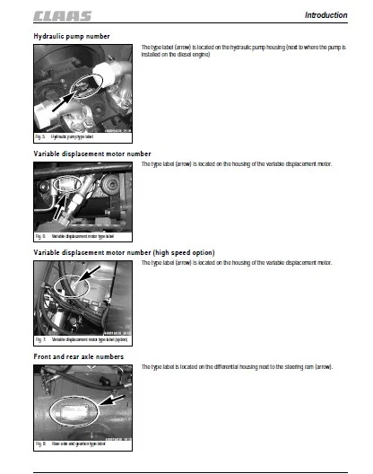
Hydraulic pump number 1-13
Variable displacement motor number 1-13
Variable displacement motor number (high speed option) 1-13
Front and rear axle numbers 1-13
Signs and symbols 1-14
Labels on the outside of the machine 1-14
Labels on the inside of the machine 1-15
Safety instructions 2
Identification of warnings and dangers 2-1
Warranty 2-1
Designated use and exemption from liability 2-2
General conduct and safety instructions 2-3
Organisational measures 2-3
Selection and qualification of staff, basic responsibilities 2-5
Safety instructions regarding operation 2-6
Normal operation 2-6
Applications with lifting gear 2-8
Trailers and attachments 2-9
Transport 2-9
Safety instructions for maintenance 2-10
Service and maintenance work on ROPS/FOPS superstructures
(ROPS bar) 2-11
Table of contents
I-2 000 295 427 0 – BA SCORPION
Table of contents
Warning of special hazards 2-12
Electric energy 2-12
Gas, dust, steam, smoke 2-12
Hydraulic equipment 2-13
Noise 2-13
Oil, grease and other chemical substances 2-13
Battery 2-13
Tyres 2-13
Operation 3
Overview of control elements 3-1
Cab overview 3-2
Instrument panel, multifunctional lever, switch consoles: overview 3-4
Telltales and warning lights: description 3-6
Telltale and warning light – instrument panel 3-6
Telltale and warning light – front instrument panel 3-7
Taking the machine into service for the first time 3-8
Safety instructions 3-8
Important information 3-8
Running-in period 3-8
Check lists 3-9
Start-up checklist 3-9
Operation checklist 3-10
Parking checklist 3-10
Cab 3-11
Opening the door from the outside and inside 3-11
Opening/closing the side window 3-12
Opening the side window 3-12
Completely opening and locking the side window 3-13
Opening/closing the rear window 3-14
Rear window emergency exit 3-14
Interior light 3-14
Before starting the engine 3-15
General 3-15
Starting the engine 3-16
Function: warning telltale in tip switch (103 kW diesel engine) 3-17
Reading out the flash code 3-17
Warning limit – coolant temperature 3-17
Warning limit – charge-air temperature 3-18
Warning limit –engine oil pressure 3-18
Overview of flashing codes 3-19
Key-based drive interlock (option) 3-22
Coding (“training”) new ignition keys 3-22
Enabling (locking) the drive interlock 3-23
Disabling (releasing) the drive interlock 3-23
Deleting coded keys 3-23
Safety functions 3-23
Drive interlock with code input (option) 3-24
Entering/changing the personal code 3-25
Enabling the drive interlock 3-25
Disabling the drive interlock 3-26
Taking the drive interlock out of service 3-27
Putting the drive interlock back into service again 3-27
Interruption of drive interlock power 3-27
Drive interlock maintenance 3-27
000 295 427 0 – BA SCORPION I-3
Table of contents
Oil and fuel preheater (option) 3-28
Oil preheater (option) 3-28
Fuel preheater (option) 3-28
Jump-starting the engine (external battery) 3-29
Safety instructions 3-29
Procedure 3-29
Before moving off 3-30
Special instructions for driving on public roads 3-30
Locking the control lever (joystick) and the 3rd control circuit (attachments) 3-31
Steering column height and angle adjustment 3-31
Checking the steering system 3-32
Synchronous wheel position 3-32
Adjusting the height of the control lever base 3-32
Accelerator pedal 3-33
Manual throttle (option) 3-33
Brake/inching pedal 3-34
Service brake 3-34
Parking brake 3-35
Moving off the telehandler 3-36
Changing direction (forwards/reverse) 3-36
Selecting the drive range (0 – 20 kph, standard) 3-37
Selecting the drive range (0 – 30/40 kph, option) 3-37
Low-speed control (option) 3-38
Electric mirror adjustment (option) 3-38
Load stabiliser 3-39
Backup warning system (option) 3-40
Differential lock 3-40
Switching on the differential lock 3-40
Switching off the differential lock 3-40
Synchronising the steering system 3-41
Changing steering mode 3-42
Front wheel steering 3-42
4 wheel steering 3-42
Changing over to diagonal steering (crab steering option) 3-43
Stopping/parking the machine 3-44
Light system 3-45
Headlights 3-45
Working lights 3-46
Signalling system 3-47
Turn indicator 3-47
Hazard warning system 3-47
Rotating beacon (option) 3-47
Cab heating and ventilation 3-48
Air conditioning (option) 3-49
Washer system 3-50
Tank for washer system 3-50
Seat 3-51
Seat adjustment 3-51
Weight adjustment 3-51
Height adjustment (air-suspension seat, option) 3-52
Backrest adjustment 3-52
Horizontal adjustment 3-52
Seat belt (lap belt) 3-53
Fastening the seat belt 3-53
Unfastening the seat belt 3-54
I-4 000 295 427 0 – BA SCORPION
Table of contents
Longer/shorter lap belt adjustment: 3-54
Engine cover 3-54
Fire extinguisher (option) 3-55
Battery master switch (option) 3-55
Reversing cooling fan (option) 3-55
Towing and transporting the machine 3-56
Getting ready for towing 3-56
Towing the machine 3-57
Once towing is over 3-57
Loading and transporting the telehandler 3-58
General safety instructions 3-58
Loading the machine 3-59
Strapping down the machine 3-59
Crane handling the machine 3-60
Safety instructions 3-60
Crane handling 3-60
Telescopic boom operation: overview 3-61
Operating the control lever for the lift, tilt and push-out rams 3-61
Operation of 3rd control circuit 3-62
Operating the telescopic boom 3-63
General safety instructions 3-63
Safe load indicator 3-63
Safe load indicator display 3-64
Disabling/enabling the lock function of the safe load indicator 3-65
Functional check of the safe load indicator 3-65
Raising/extending the telescopic boom 3-66
Retracting/lowering the telescopic boom 3-67
Emergency lowering of the telescopic boom in case of a diesel engine
breakdown 3-67
Re-equipping attachments 3-68
Driving on public roads with an attachment 3-68
Pressure relief on the quick couplers and the quickhitch facility 3-68
Fitting an attachment onto the hydraulic quickhitch facility 3-69
Fitting an attachment onto the mechanical quickhitch facility (option) 3-70
“Hose burst valve” safety feature 3-71
Mounting/removing the pallet forks 3-72
Driving on public roads with the pallet forks 3-72
Adjusting the fork arms 3-73
Working with the pallet forks 3-74
General safety instructions 3-74
Specific safety instructions 3-75
Brief instructions for fork arms 3-76
Load diagram for pallet forks (EN 1459/1998) 3-77
Approaching the material 3-78
Loading the material 3-78
Picking up material and setting it down in a high position 3-79
Working with the standard bucket 3-80
General instructions 3-80
Bucket payloads 3-80
Practical hints for digging 3-81
Tilt position of the bucket 3-81
Transport position of the bucket 3-81
Transporting with a full bucket 3-82
Loading loose material 3-82
Loading if the material is hard to penetrate 3-83
Removing material/digging in soft soil 3-83
Removing material/digging in hard soil 3-84
000 295 427 0 – BA SCORPION I-5
Table of contents
Grading 3-84
Loading vehicles 3-85
Freeing the machine 3-85
Working with a crane jib (option) 3-86
Continuous operation of 3rd control circuit (option) 3-87
Operation: electric changeover valve for front additional control circuit (option) 3-88
Operation: front/rear additional hydraulic control circuit (option) 3-89
Tipping trailer operation (option) 3-90
Connection of electrically operated attachments (option) 3-90
Operation of the Autohitch trailer coupling (option) 3-91
Trailer coupling operation (option) 3-92
Compressed-air brake system (option) 3-93
General safety instructions 3-93
Coupling and uncoupling compressed-air hoses (dual-circuit brake system) 3-93
Compressed-air gauge 3-94
Hydraulic trailer brake connection (option) 3-94
Fitting attachments from other manufacturers onto the quickhitch facility (option) 3-95
Example: inspection plan for attachments from other manufacturers 3-96
Troubleshooting 4
Diesel engine malfunctions 4-1
Malfunctions in the air conditioning system (option) 4-3
Maintenance 5
Important information on maintenance work 5-1
Safety prop for telescopic boom 5-1
Fuel system 5-2
Specific safety instructions 5-2
Refuelling 5-2
Stationary fuel pumps 5-2
Diesel fuel specification 5-3
Checking/replacing the fuel prefilter (water separator) 5-3
Replacing the fuel filter 5-4
Bleeding the fuel system 5-5
Engine lubrication system 5-6
Checking the engine oil level 5-6
Filling up engine oil 5-7
Replacing the engine oil every 500 s/h (service hours) 5-8
Replacing the engine oil filter cartridge every 500 s/h (service hours) 5-9
Engine and hydraulics cooling system 5-10
Specific safety instructions 5-10
Checking the coolant level and quality 5-11
Filling up coolant 5-12
Draining coolant 5-13
Cleaning the radiator fins 5-14
Cleaning the radiator with the reversing fan (option) 5-15
Air filter 5-16
Checking air filter contamination 5-16
Replacing the filter cartridge at 500 s/h (service hours) 5-17
V-belt 5-18
Checking the V-belts 5-18
Retightening the V-belt 5-18
Hydraulic system 5-19
Specific safety instructions 5-19
Monitoring the hydraulic oil and the reflux filter 5-20
Checking the hydraulic oil level once a day 5-20
Filling up the hydraulic oil 5-21
I-6 000 295 427 0 – BA SCORPION
Table of contents
Important information for the use of biodegradable oil 5-21
Checking hydraulic pressure lines 5-22
Specific safety instructions 5-22
Lubrication work 5-23
General safety instructions 5-23
Lubricating the rear axle oscillation-type bearing 5-23
Lubricating the planetary drive bearing 5-23
Lubrication points on the telescopic boom: overview 5-24
Lubricating the telescopic boom 5-24
Checking and adjusting the wear plates 5-24
Lubricating with the central lubrication system (option) 5-25
General functional description 5-25
Setting the lubrication and break times 5-26
Filling the central lubrication system 5-26
Maintenance of the brake system 5-27
Specific safety instructions 5-27
Checking/filling up the brake fluid level 5-27
Maintenance: compressed-air brake system (option) 5-28
Checking the compressed-air tank and lines 5-28
Checking compressor attachment and drive 5-28
Tyres 5-29
Daily tyre checks 5-29
Changing wheels 5-30
Heating – fresh air 5-31
Cleaning/replacing the fine-dust filter 5-31
Cleaning/replacing the recirculated-air filter 5-31
Air conditioning (option): maintenance 5-32
General safety instructions 5-32
Functional and visual check once a day 5-33
Maintenance of the electric system 5-34
Specific safety instructions 5-34
Service and maintenance work at regular intervals 5-34
Cables, bulbs and fuses 5-35
Alternator 5-35
Adjusting the headlights 5-35
Checking/replacing the battery 5-36
Maintenance: trailer coupling 5-37
Trailer coupling (option) 5-37
General maintenance work 5-38
Specific safety instructions 5-38
When using washing solvents 5-38
When using compressed air 5-38
When using a high-pressure cleaner or steam jet 5-38
When using volatile and easily flammable anticorrosion agents and sprays 5-38
Cleaning inside the cab 5-39
Cleaning the seat belt 5-39
Cleaning the exterior of the machine 5-39
Cleaning the engine and the engine compartment 5-40
Screw connections 5-40
Pivots and hinges 5-40
000 295 427 0 – BA SCORPION I-7
Table of contents
Maintenance work “Aggressive Media” (option) 5-41
Anticorrosion protection applied in the factory 5-41
Components coated with anticorrosive wax 5-41
Measures for maintaining anticorrosive protection 5-42
Applying the protective anticorrosion coating 5-43
Treatment of oxidised surfaces 5-43
Maintenance and service of the attachments 5-43
Maintenance plan (overview) 5-45
Fluids and lubricants 5-49
Maintenance label 5-50
Explanation of symbols on the maintenance label 5-50
Maintenance label 5-51
Specifications 6
Model and trade names: overview 6-1
Frame 6-1
Engine 6-1
Oil/water cooling fan 6-2
Power train 6-2
Variable displacement pump 6-2
Variable displacement motor 6-2
Axles 6-3
Front axle 6-3
Rear axle 6-3
Service and parking brake 6-4
Steering system 6-4
Work hydraulics 6-5
Hydraulic pump 6-5
Hydraulic ram protection 6-5
Lift, tilt and push-out rams: velocity 6-6
Hydraulic pilot control 6-6
Additional control circuit (option) 6-6
Electric system 6-7
Fuses: overview 6-7
Electric components 6-8
Main fuse box with relays (88 kW diesel engine) 6-9
Main fuse box with relays (103 kW diesel engine) 6-9
Relays: overview 6-10
Tyres for models 400-01/401-03/402-03/403-03 6-11
Weights 6-12
Noise levels 6-12
Vibration 6-12
Coolant compound table 6-12
Tightening torques 6-13
General tightening torques 6-13
Specific tightening torques 6-13
Trailer couplings: trailer weight/drawbar load 6-13
Payload: model 400-01 load diagram 6-14
Payload: models 401-03 load diagram 6-15
Payload: model 402-03 load diagram 6-16
Payload: models 403 03 load diagram 6-17
Dimensions with bucket 6-18
Dimensions with pallet forks 6-19
I-8 000 295 427 0 – BA SCORPION
Index
Index
Symbole
“Hose burst valve” safety feature3-71
A
Abbreviations 1-1
Accident prevention regulations German inspection and
certification body for agriculture and forestry)1-7, 3-95
For machines1-7, 3-95
Adjusting fork arms distance3-73
Adjusting the headlights5-35
Adjusting the height of the control lever base3-32
Air conditioning (option) 3-49
Air filter5-16
Cleaning the dust collector 5-16
Dust valve5-16
Applications with lifting gear 2-8
B
Battery master switch (option) 3-55
Biodegradable oil 5-21
Brake system5-27
Brake fluid5-27
Safety instructions 5-27
C
Cab
Doors3-11
Side window 3-12
Central lubrication system (option) 5-25
Charge-air temperature 3-18
Check lists 3-9
Checking and adjusting the wear plates5-24
Cleaning
Exterior of the machine5-39
Inside the cab 5-39
Motor and engine compartment5-40
Seat belt 5-39
Specific safety instructions 5-38
Cleaning and maintenance
Maintenance work if the machine is used in
a saline environment 5-41
Compressed-air brake system (option)3-93
Coolant temperature 3-17
Crane jib (option) 3-86
D
Designated use and exemption from liability 2-2
Documents1-7
Driving licence 1-6
Driving on public roads
With bucket3-30
E
Electric system6-7
Emergency lowering of the telescopic boom in case of a diesel engine
breakdown 3-67
Engine oil pressure 3-18
Error code displays (103 kW diesel engine) 3-17
F
Fitting an attachment onto the quickhitch facility 3-69
Fitting attachments from other manufacturers onto the quickhitch
facility (option)3-95
Fluids and lubricants5-49
Fuel preheater (option) 3-28
Fuel system
Bleeding5-5
Cleaning the water separator 5-3
H
Hazard warning system3-47
Heating 3-48
Fine-dust filter5-31
Heating, fresh air 3-48
Heating, mixed mode3-48
Heating, recirculated air mode3-48
Recirculated-air filter5-31
I
Important information
On this Operator’s Manual1-1
Interior light 3-14
K
Key-based drive interlock (option) 3-22
L
Legal regulations 1-6
Licence, equipment1-6
Light system3-45
Load diagram3-77
Load stabiliser (option)3-39
Loading and transporting 3-58
Loading tie-bar3-60
Locking and unlocking the engine cover3-54
Lowering the telescopic boom with the engine switched off 3-67
Lubrication points
Planetary drive bearing of axle5-23
Rear axle oscillation-type bearing 5-23
Telescopic boom 5-24
Index
000 295 427 0 – BA SCORPION I-9
Index
M
Machine
Brief description1-3
Fields of application1-4
Overview 1-2
Machine inspections 1-7
Maintenance
Air filter cartridge 5-17
Biodegradable oil5-21
Brake system5-27
Changing wheels5-30
Checking the coolant level 5-11
Checking the engine oil level5-6
Checking the hydraulic oil level 5-20
Compressed-air brake system (option) 5-28
Electric system 5-34
Engine and hydraulics cooling system 5-10
Engine lubrication system5-6
Filling in engine oil5-7
Filling up coolant 5-12
Filling up hydraulic oil 5-21
Fluids and lubricants 5-49
Fuel system5-2
Heating5-31
Hydraulic pressure lines 5-22
Hydraulic system5-19
Maintenance of attachments 5-43
Pivots and hinges5-40
Replacing the engine oil filter cartridge 5-9
Screw connections 5-40
Service and maintenance work 5-38
Service and maintenance work at regular intervals5-34
Trailer couplings5-37
Tyre care 5-29
V-belt 5-18
Maintenance plan 5-45
Model designation – trade names 1-3
N
Noise levels 1-14
O
Oil preheater (option)3-28
Operation
Before moving off 3-30
Changing direction (forwards/reverse) 3-36
Fire extinguisher (option)3-55
Hose burst valve on tilt ram3-71
Load stabiliser 3-39
Moving off 3-36
Parking the machine3-44
Reversing cooling fan (option)3-55
Seat belt height adjustment3-53
Selecting the drive range (high speed)3-37
Selecting the drive range (standard) 3-37
Starting the engine 3-15
P
Pallet forks3-74
Approaching the material 3-78
Brief instructions for fork arms3-76
Fitting/removing3-72
Loading the material3-78
Locking lever for fork arms3-73
Safety instructions 3-74
Specific safety instructions3-75
Parking brake 3-35
Picking up an attachment with the mechanical
quickhitch facility3-70
Q
Quickhitch facility
Releasing the pressure on the quick couplers 3-68
R
Radiator
Draining coolant 5-13
Rear window emergency exit 3-14
Refuelling 5-2
Rotating beacon 3-47
Running-in period 3-8
S
Safe load indicator3-64
Functional check 3-65
Measures to be taken if 3-64
Safety instructions 2-1
Applications with lifting gear 2-8
General conduct 2-3
Identification 2-1
Maintenance2-10
Operation 2-6
Special hazards2-12
Trailers and attachments 2-9
Transport 2-9
Seat adjustment3-51
Backrest adjustment3-52
Horizontal adjustment3-52
Seat belt 3-53
Adjustment 3-54
Fastening the seat belt 3-53
Separate certification for attachments depending on
the legal regulations of your country 1-4
Service brake3-34
Signalling system3-47
Signs and symbols 1-14
I-10 000 295 427 0 – BA SCORPION
Index
Specifications6-1
Additional control circuit (option) 6-6
Axles6-3
Brakes 6-4
Coolant compound table6-12
Dimensions with bucket6-18
Dimensions with pallet forks 6-19
Drive 6-2
Electric components 6-8
Engine 6-1
Frame 6-1
Front axle6-3
Hydraulic pump6-5
Hydraulic ram protection6-5
Load diagram6-14
Main fuse box with relays 6-9
Model and trade names6-1
Noise levels 6-12
Oil/water cooling fan6-2
Pilot control6-6
Rear axle 6-3
Relays (overview) 6-10
Steering system6-4
Tightening torques6-13
Trailer couplings 6-13
Tyres6-11
Variable displacement motor 6-2
Variable displacement pump 6-2
Vibration 6-12
Weights6-12
Work hydraulics6-5
Speed
Lift, tilt and push-out rams 6-6
Stability
Pallet forks3-72
Starting aid3-29
Steering mode
Diagonal steering (crab steering option)3-43
Synchronous wheel position3-32
T
Taking into service
Check lists 3-9
Safety instructions 3-8
Taking the machine into service for the first time 3-8
Telescopic boom
Checking the tilt position of the bucket 3-81
Checking the transport position of the bucket 3-81
Extending/raising 3-66
Lubrication 5-24
Retract/lower 3-67
Telltales 3-6
Towing and transporting the machine3-56
Trailer coupling 3-92
Trailer weight/drawbar load6-13
Transport 3-82
Turn indicator3-47
Tyre care5-29
V
Ventilation 3-48
Ventilation, fresh air3-48
W
Warning identification1-7
Warranty 2-1
Washer pump 3-50
Washer system
Tank3-50
Wheel change5-30
Wipers3-50
Working
Approaching the material3-78
Freeing the machine3-85
Grading3-84
Loading loose material 3-82
Loading the material 3-78
Practical hints 3-85
Removing material/digging in hard soil3-84
Removing material/digging in soft soil 3-83
Setting down the material 3-79
With a crane jib (option)3-86
With the pallet forks 3-74
Working lights 3-46
IMAGES PREVIEW OF THE MANUAL:
CLAAS SCORPION 7045 (403-03) 7040 (402-03) 7030 (401-03) 6030 (400-01) OPERATOR’S MANUAL – PDF DOWNLOAD:
PLEASE NOTE:
- This is not a physical manual but a digital manual – meaning no physical copy will be couriered to you. The manual can be yours in the next 2 mins as once you make the payment, you will be directed to the download page IMMEDIATELY.
- This is the same manual used by the dealers inorder to diagnose your vehicle of its faults.
- Require some other service manual or have any queries: please WRITE to us at [email protected]
S.M