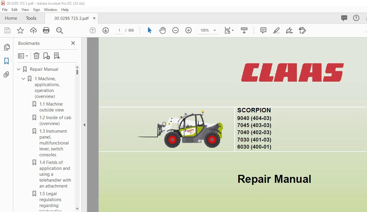
CLAAS SCORPION 9040 (404-03) 7045 (403-03) 7040 (402-03) 7030 (401-03) 6030 (400-01) Repair Manual – PDF DOWNLOAD
Original price was: $89.00.$28.95Current price is: $28.95.
CLAAS SCORPION 9040 (404-03) 7045 (403-03) 7040 (402-03) 7030 (401-03) 6030 (400-01) Repair Manual – PDF DOWNLOAD
Description
CLAAS SCORPION 9040 (404-03) 7045 (403-03) 7040 (402-03) 7030 (401-03) 6030 (400-01) Repair Manual – PDF DOWNLOAD
DESCRIPTION:
CLAAS SCORPION 9040 (404-03) 7045 (403-03) 7040 (402-03) 7030 (401-03) 6030 (400-01) Repair Manual – PDF DOWNLOAD
Language :English
Pages :806
Downloadable : Yes
File Type : PDF
Size:92.8 mb
TABLE OF CONTENTS:
CLAAS SCORPION 9040 (404-03) 7045 (403-03) 7040 (402-03) 7030 (401-03) 6030 (400-01) Repair Manual – PDF DOWNLOAD
Table of Contents
1 Machine, applications, operation (overview)
11 Machine outside view 1-2
12 Inside of cab (overview) 1-3
13 Instrument panel, multifunctional lever, switch consoles (overview) 1-4
14 Fields of application and using a telehandler with an attachment 1-5
15 Legal regulations regarding telehandler operation 1-8
16 Type labels and component numbers 1-11
2 Specifications
21 Model and trade names (overview) 2-2
22 Frame 2-2
23 Engine 2-2
24 Oil/water fan 2-3
25 Drive 2-3
26 Axles 2-4
27 Service and parking brake 2-4
28 Steering system 2-5
29 Work hydraulics 2-6
210 Electrical system 2-8
211 Tyres for models 401-03/402-03/403-03 2-12
212 Tyres for model 404-03 2-12
213 Machine weights, axle loads 2-13
214 Noise levels 2-13
215 Vibrations, oscillation and acceleration value 2-14
216 Coolant compound table 2-14
217 Tightening torques 2-15
218 Trailer couplings: trailer weight/drawbar load 2-15
219 Pallet forks model 400-01 2-16
220 Load on pallet forks model 401-03 (without counterweight) 2-17
221 Load on pallet forks model 401-03 (with counterweight 2 x 150 kg) 2-18
222 Pallet forks model 402-03 (with counterweight 2 x 150 kg) 2-19
223 Pallet forks model 402-03 (with counterweight 2 x 300 kg) 2-20
224 Load on pallet forks model 403-03 2-21
225 Payloads model 404-03 2-22
226 Dimensions with bucket 2-26
227 Dimensions with bucket 2-27
228 Dimensions with pallet forks 2-28
229 Dimensions with pallet forks 2-29
3 Maintenance and servicing work
31 Explanation of symbols on the maintenance label 3-2
32 Maintenance label 3-3
33 Fluids and lubricants (overview) 3-4
34 Maintenance plan 3-5
35 Introduction 3-9
36 Safety prop for telescopic boom 3-9
37 Fuel system 3-10
38 Maintenance of engine lubrication system 3-14
39 Maintenance of the engine and hydraulics cooling system 3-18
310 Cleaning the radiator with the reversing fan (option) 3-23
311 Air filter maintenance 3-24
312 Maintenance: V-belts 3-26
313 Gearbox and axle maintenance 3-27
Table of Contents
I-2 00 0295 725 2 – RHB SCORPION
Table of Contents
314 Safety instructions regarding the hydraulic system 3-32
315 Monitoring the hydraulic oil and the return filter 3-33
316 Checking the hydraulic oil level 3-33
317 Filling up hydraulic oil 3-34
318 Replacing the return filter of the hydraulic system 3-34
319 Replacing the microfilter of the hydraulic system 3-34
320 Replacing the microfilter in the LS line 3-35
321 Replacing hydraulic oil 3-36
322 Important notices on the use of biodegradable oil 3-37
323 Checking hydraulic pressure lines 3-38
324 Lubrication work 3-39
325 Maintenance of the brake system 3-42
326 Replacing/bleeding the service brake fluid with bleed equipment 3-43
327 Maintenance of compressed-air brake system (option) 3-46
328 Tyre maintenance 3-47
329 Heating and ventilation maintenance 3-49
330 Maintenance of air conditioning (option) 3-50
331 Maintenance of the electrical system 3-55
332 Maintenance of trailer coupling 3-59
333 General maintenance work on the machine 3-60
334 Cleaning inside the cab 3-61
335 Cleaning the seat belt 3-61
336 Cleaning the exterior of the machine 3-61
337 Checking screw connections 3-61
338 Checking pivots and hinges 3-61
339 Cleaning the engine compartment 3-62
340 Maintenance and servicing work “Aggressive Media” 3-63
341 Maintenance and servicing of attachments on the quickhitch 3-65
4 Engine
41 Electrical system/hydraulics – fan (electrical diagram) 4-2
42 Fan (functional description) 4-6
43 Fan connector assignment for models 402, 403, 404 4-7
44 Diesel engine connector assignment (88 kW) 4-8
45 Diesel engine connector assignment (103 kW) 4-9
46 Fuel preheater connector assignment 4-10
47 Diagnosis connector assignment 4-11
48 88 kW diesel engine electrical system (electrical diagram) 4-14
49 103 kW diesel engine electrical system (electrical diagram) 4-18
410 Fuel preheater (electrical diagram) 4-22
411 Engine diagnosis (electrical diagram) 4-24
412 Engine oil cooler side (88 kW) (overview) 4-25
413 Engine drive side (88 kW) (overview) 4-26
414 Engine turbocharger side (88 kW) (overview) 4-27
415 Engine oil cooler side (103 kW) (overview) 4-28
416 Fuel: high-pressure unit 4-29
417 Engine drive side (103 kW) (overview) 4-30
418 Engine turbocharger side (103 kW) (overview) 4-31
419 Electronics overview (103 kW) 4-32
420 Electronic engine speed setting (103 kW) (overview) 4-35
421 Function: warning indicator light in tip switch (103 kW diesel engine) 4-36
422 Engine drive – clutch (88/103 kW) (overview) 4-41
423 Installing the fan pump 4-42
424 Fuel system (88/103 kW) (overview) 4-43
425 Bleeding the fuel system (88/103 kW) 4-44
426 Fan circuit (not in reversing operation) 4-45
427 Fan circuit with reversing fan 4-46
00 0295 725 2 – RHB SCORPION I-3
Table of Contents
428 Reversing valve block 4-47
429 Setting maximum fan speed (reversing fan) 4-48
430 Setting maximum fan speed (without reversing fan) 4-48
431 Cleaning the radiator with the reversing fan (option) 4-49
432 Function: reversing fan operation 4-50
5 Power train
51 40 kph drive hydraulic diagram for models 400, 401, 402 5-2
51 30 – 40 kph drive hydraulic diagram for models 402, 403, 404 5-4
52 40 kph drive hydraulic diagram for models 402 – 404 5-6
53 Drive hydraulic diagram (designations) 5-7
54 40 kph drive electrics diagram for models 402, 403, 404 5-10
55 30 – 40 kph drive electrics diagram for models 400 – 404 5-12
56 Electrical diagram (designations) 5-13
57 Functional despcription of drive hydraulics and electrical system 5-15
58 Drive electrics connector assignment for models 400 – 404 5-18
59 Towing and transporting the machine 5-19
510 Hydraulic pump TMP 89 (models 402, 403, 404) 5-21
511 Hydraulic pump H1 P078 (models 400, 401, 402) 5-22
512 High speed gearbox (0 – 40 kph) 5-23
513 High-speed gearbox with auxiliary motor (0 – 40 kph) 5-23
514 Function without auxiliary motor (0 – 40 kph) 5-24
515 Function with auxiliary motor (0 – 40 kph) 5-24
516 Gearbox overview (0 – 40 kph) 5-25
517 Overview of control cover and diagram up to serial no (0 – 40 kph) 5-26
518 Overview of control cover and diagram from serial no (0 – 40 kph) 5-27
519 Control cover component parts for gearbox (0 – 40 kph) 5-28
520 Hydraulic drive circuit (0 – 40 kph) 5-29
521 Legend for gearbox circuit diagram (0 – 40 kph) 5-30
522 Gearbox circuit diagram (0 – 40 kph) 5-31
523 Legend for gearbox circuit diagram with auxiliary motor (0 – 40 kph) 5-32
524 Gearbox circuit diagram with auxiliary motor (0 – 40 kph) 5-33
525 Measurement reports 5-34
526 Test report for model 400/401/402 with H1 pump without auxiliary motor
(0 –40 kph) 5-36
527 Test report for model 403/404/402 with TMP89 pump and auxiliary motor
(fixed displacement motor) (0 – 40 kph) 5-37
528 Test report for model 403/404 diesel engine 103 kW and TMP89 pump and
auxiliary motor (variable displacement motor) (0 – 40 kph) 5-38
529 Test report for model 402/403/404 (30 kph) 5-39
530 Error description for test report 5-40
531 Checking and setting boost pressure (0 – 40 kph gearbox) 5-41
532 Checking high pressure (0 – 40 kph) 5-42
533 Checking engine droop (pump) (0 – 40 kph) 5-43
534 Checking driving direction identification (0 – 40 kph) 5-44
535 Setting engine droop on the gearbox with/without auxiliary motor (fixed displacement motor 0 – 40 kph) 5-45
536 Control initiation set screw (0 – 40 kph gearbox) 5-46
537 Checking the cardan shaft speed (0 – 40 kph gearbox) 5-47
538 Troubleshooting work on drive 5-48
539 Hydraulic pump report 5-49
540 Report for measurement 1 of hydraulic pump (engine speed and boost pressure) 5-50
541 Report for forward/reverse measurement 2 of hydraulic pump 5-51
542 Report for measurement of forward driving direction of hydraulic pump: 5-52
543 Report for forward measurement 3 of hydraulic pump: 5-53
544 Variable displacement pump test for models 400/401 and 402 5-54
545 Variable displacement pump test for models 402/403/404 5-56
546 Checking the high-speed gearbox 5-58
I-4 00 0295 725 2 – RHB SCORPION
Table of Contents
547 Measurement 1 (driving direction identification) 5-59
548 Measurement 2 (M4 pressure at shuttle throttle) 5-59
549 Measurements 3 and 4 (proportional solenoid and proportional regulator) 5-60
550 Measurement 5 (pressure relief valve M3, PCOR valve) 5-60
551 High-speed gearbox report: measurement 1 (driving direction identification) 5-61
552 High-speed gearbox report: measurement 2 (M4 shuttle pressure) 5-62
553 High-speed gearbox report: measurements 3 and 4 (proportional solenoid and proportional regulator) 5-63
554 Report: measurement 5 (pressure relief valve M3, PCOR valve) 5-64
555 Repair work on the high-speed gearbox 5-65
556 Repair work on the high-speed gearbox 5-68
557 Repair work on the high-speed gearbox 5-69
558 Checking or replacing the shuttle throttle 5-72
559 Removing the shuttle throttle 5-73
560 Installing the shuttle throttle 5-76
561 Checking the auxiliary motor 5-77
562 Switching off rear axle/4 wheel drive 5-78
563 Disabling 4 wheel drive (overview) 5-79
564 Installation position 5-80
565 Drive electronics Operator’s Manual (SUSMIC) 5-81
566 Error table 5-82
567 Checking the proportional valves by means of current measurement 5-83
568 Removing the consumers circuit from the hydraulic drive 5-84
569 Sealing work on the drive shaft (0 – 40 kph gearbox) 5-85
570 Mounting the rotary shaft seal (0 – 40 kph gearbox) 5-86
571 Mounting the drive flange (0 – 40 kph gearbox) 5-87
572 Sealing the Ecospeed gearbox 5-88
573 Removing the control cover (old) from the Ecospeed gearbox 5-89
574 Travelling drive with reduced engine speed 5-98
575 Overview: auxiliary motor (variable displacement motor) 5-99
576 Overview: auxiliary motor (variable displacement motor) 5-100
577 Checking control initiation/engine droop of auxiliary motor
(variable displacement motor) 5-101
578 Drive (electrical diagram) 5-104
579 20 kph hydraulic drive diagram for models 400 – 404 5-106
580 Drive hydraulic diagram (descriptions) 5-107
581 Functional despcription of drive hydraulics and electrical system 5-109
582 Drive electrics connector assignment for models 400 – 404 5-112
583 Variable displacement motor 110 cm3/rev (20 kph) 5-113
584 Variable displacement motor 110 cm3/rev (20 kph, seen from the side) 5-114
585 Variable displacement motor 160 cm3/rev (20 kph) 5-115
586 Test report for model 400 – 404 (20 kph) 5-116
587 Error description for test report models 400/401 (20 kph) 5-117
588 Hydraulic circuit: drive with hydraulic pump H1 P078 (20 kph) 5-118
589 Hydraulic circuit: drive with hydraulic pump TMP 89 (20 kph) 5-119
590 Setting boost pressure (20 kph) 5-120
591 Checking high pressure (20 kph) 5-121
592 Checking engine droop – variable displacement pump (20 kph) 5-122
593 Setting engine droop – hydraulic motor (20 kph) 5-123
594 Setting final speed (20 kph) 5-124
6 Axles/differential lock
61 Differential lock diagrams (serial no) 6-2
62 Designations: differential lock electrical diagram 6-3
63 Differential lock diagrams 6-6
64 Functional description of differential lock 6-7
65 Differential lock connector assignment 6-8
66 20 kph gearbox (overview) 6-9
00 0295 725 2 – RHB SCORPION I-5
Table of Contents
67 Removing the 20 kph gearbox 6-10
68 Installing the 20 kph gearbox 6-17
69 Front and rear axle flanges 6-25
610 Type label and oil filler neck (overview) 6-26
611 Conversion table and tightening torques 6-27
612 Removing the joint housing 6-28
613 Installing the joint housing 6-30
614 Removing the double cardan shaft 6-31
615 Mounting the double cardan shaft 6-33
616 Remove the planetary drive 6-35
617 Replacing the seals of the planetary drive 6-37
618 Installing the planetary drive 6-38
619 Installing the planetary drive 6-40
620 Sealing the front axle differential 6-42
621 Removing the front axle differential lock 6-44
622 Installing the front axle differential lock 6-47
623 Differential lock: hydraulic circuit 6-50
624 Special tools (overview) 6-51
7 Brakes
71 Brake (20 kph) diagrams (electric/hydraulic) 7-2
72 Brake (40 kph) diagrams (electric/hydraulic) 7-4
73 Hydraulic diagram – trailer brake valve 7-6
74 Designations: hydraulic brake diagram 7-7
75 Designations: electric brake diagram 7-8
76 Functional description of brakes 7-9
77 Brakes connector assignment 7-10
78 40 kph brake circuit (overview) 7-11
79 20 kph brake circuit (overview) 7-12
710 Disabling (releasing) the parking brake in the front axle 7-13
711 Enabling (adjusting) the parking brake in the front axle 7-13
712 Wear check: service brake discs 7-14
713 Setting the brake linkage – master brake cylinder 7-14
714 Service and parking brake (overview) 7-15
715 Removing the brake discs 7-16
716 Brake discs (overview) 7-19
717 Installing the brake pistons of the service and parking brake 7-20
718 Installing the belleville spring washers and the brake cylinder housing 7-21
719 Installing the service brake 7-23
720 Towing and transporting the machine 7-26
721 Hydraulic trailer brake circuit (option) 7-28
722 Air compressor 7-29
723 Air compressor overview 7-30
724 Air compressor components 7-31
725 Valves (air compressor) 7-32
726 Circuit (air compressor) 7-33
8 Steering system
81 Electrical/hydraulic diagrams for steering system up to serial no 400 01 0167, 401 03 0195, 402 03 0176, 403 03 0145, 404 03
0146 8-2
82 Electrical/hydraulic diagrams for steering system from serial no 400 01 0168, 401 03 0196, 402 03 0177, 403 03 0146, 404 03
0147, 8-4
83 Designations: electric steering diagram 8-5
84 Designations: hydraulic steering diagram 8-6
85 Functional description of steering system 8-7
86 Steering system connector assignment 8-8
I-6 00 0295 725 2 – RHB SCORPION
Table of Contents
87 Steering circuit with variable displacement pump (LS = load sensing) 8-9
88 Hydraulic steering diagram: priority valve – variable displacement pump
(LS = load sensing) 8-10
89 Steering circuit with gear pump 8-11
810 Hydraulic steering diagram: priority valve – gear pump 8-12
811 Hydraulic steering diagram: 4 wheel steering/front axle steering 8-13
812 Diagonal steering circuit (crab steering) 8-14
813 Hydraulic steering diagram: front axle steering with diagonal steering valve (crab steering) 8-15
814 Hydraulic steering diagram: diagonal steering with diagonal steering valve (crab steering) 8-16
815 Hydraulic steering diagram: 4 wheel steering with diagonal steering valve
(crab steering) 8-17
816 Steering system goes out of line (20/40 kph) 8-18
817 Steering valve (overview) 8-19
818 Pressure relief valve – servostat: settings 8-20
819 Front and rear axle steering sensor (magnetic sensor) 8-21
820 Removing the steering rams 8-22
821 Installing the steering rams 8-26
822 Adjusting the steering angle 8-30
9 Work hydraulics
91 Work hydraulics fixed displacement pump (diagram) – raising/lowering the telescopic boom (HUSCO) 9-2
92 Work hydraulics fixed displacement pump (diagram) – raising/lowering the telescopic boom (Bucher) 9-4
93 Work hydraulics variable displacement pump (diagram) – raising/lowering the telescopic boom (HUSCO) 9-6
94 Work hydraulics variable displacement pump (diagram) – raising/lowering the telescopic boom (Bucher) 9-8
95 Raising/lowering the telescopic boom (electrical diagram) 9-10
96 Load stabiliser (electrical diagram) 9-12
97 Work hydraulics (diagram) – extending/retracting the telescopic boom, fixed displacement pump (HUSCO) 9-14
98 Work hydraulics fixed displacement pump (diagram) – extending/retracting the telescopic boom 9-16
99 Work hydraulics variable displacement pump (diagram) – extending/retracting the telescopic boom (HUSCO) 9-18
910 Work hydraulics variable displacement pump (diagram) – extending/retracting the telescopic boom (Bucher) 9-20
911 Work hydraulics variable displacement pump (diagram) – extending/retracting the telescopic boom 9-22
912 Extending/retracting the telescopic boom (electrical diagram) 9-24
913 Retracting/extending the telescopic boom (designations) 9-25
914 Work hydraulics fixed displacement pump (diagram) – dumping in/out (HUSCO) 9-28
915 Work hydraulics fixed displacement pump – dumping in/out (diagram) 9-30
916 Work hydraulics variable displacement pump (diagram), dumping in/out (HUSCO) 9-32
917 Work hydraulics variable displacement pump (diagram) – dumping in/out (Bucher) 9-34
918 Dumping in/out (electrical diagram) 9-36
919 4 wheel drive OFF (electrical diagram) 9-38
920 Dumping in/out (electrical diagram) 9-40
921 Bucket repositioning (electrical diagram) 9-42
922 Work hydraulics fixed displacement pump (diagram) – locking/unlocking (HUSCO) 9-44
923 Work hydraulics fixed displacement pump (diagram) – locking/unlocking (Bucher) 9-46
924 Work hydraulics variable displacement pump (diagram) – locking/unlocking (HUSCO) 9-48
925 Work hydraulics variable displacement pump (diagram) – locking/unlocking (Bucher) 9-50
926 Locking/unlocking (electrical diagram) 9-52
927 Work hydraulics fixed displacement pump (diagram) – rear additional control circuit (HUSCO) 9-54
928 Work hydraulics fixed displacement pump (diagram) – additional control circuit (Bucher) 9-56
929 Work hydraulics variable displacement pump (diagram) – rear additional control circuit (HUSCO) 9-58
930 Work hydraulics variable displacement pump (diagram) – additional control circuit (Bucher) 9-60
931 Work hydraulics fixed displacement pump (diagram) – rear additional control circuit, Autohitch (HUSCO) 9-62
932 Work hydraulics fixed displacement pump (diagram) – additional control circuit, Autohitch (Bucher) 9-64
933 Work hydraulics variable displacement pump (diagram) – rear additional control circuit, Autohitch (HUSCO) 9-66
934 Work hydraulics variable displacement pump (diagram) – additional control circuit, Autohitch (Bucher) 9-68
935 Work hydraulics fixed displacement pump (diagram) – rear additional control circuit, Autohitch, tipping trailer (HUSCO) 9-70
936 Work hydraulics fixed displacement pump (diagram) – additional control circuit, Autohitch, tipping trailer (Bucher) 9-72
937 Work hydraulics variable displacement pump (diagram) – rear additional control circuit, Autohitch, tipping trailer (HUSCO)
00 0295 725 2 – RHB SCORPION I-7
Table of Contents
9-74
938 Work hydraulics variable displacement pump (diagram) – additional control circuit, Autohitch, tipping trailer (Bucher) 9-76
939 Work hydraulics fixed displacement pump (diagram) – rear additional control circuit, tipping trailer (HUSCO) 9-78
940 Work hydraulics fixed displacement pump (diagram) – additional control circuit, tipping trailer (Bucher) 9-80
941 Work hydraulics variable displacement pump (diagram) – rear additional control circuit, tipping trailer (HUSCO) 9-82
942 Work hydraulics variable displacement pump (diagram) – additional control circuit, tipping trailer (Bucher) 9-84
943 Work hydraulics fixed displacement pump (diagram) – Autohitch (HUSCO) 9-86
944 Work hydraulics fixed displacement pump (diagram) – Autohitch (Bucher) 9-88
945 Work hydraulics variable displacement pump (diagram) – Autohitch (HUSCO) 9-90
946 Work hydraulics variable displacement pump (diagram) – Autohitch (Bucher) 9-92
947 Work hydraulics fixed displacement pump (diagram) – Autohitch, tipping trailer (HUSCO) 9-94
948 Work hydraulics fixed displacement pump (diagram) – Autohitch, tipping trailer (Bucher) 9-96
949 Work hydraulics variable displacement pump (diagram) – Autohitch, tipping trailer (HUSCO) 9-98
950 Work hydraulics variable displacement pump (diagram) – Autohitch, tipping trailer (Bucher) 9-100
951 Work hydraulics fixed displacement pump (diagram) – tipping trailer (HUSCO) 9-102
952 Work hydraulics fixed displacement pump (diagram) – tipping trailer (Bucher) 9-104
953 Work hydraulics variable displacement pump (diagram) – tipping trailer (HUSCO) 9-106
954 Work hydraulics variable displacement pump (diagram) – tipping trailer (Bucher) 9-108
955 Work hydraulics variable displacement pump (diagram) – additional control circuit for quick couplers on telescopic boom (HUSCO)
9-110
956 Work hydraulics fixed displacement pump (diagram) – additional control circuit for quick couplers on telescopic boom 9-112
957 Work hydraulics (diagram) – safe load indicator 9-114
958 Work hydraulics (diagram) – safe load indicator (HUSCO) 9-116
959 Front/rear additional control circuit for quick couplers, Autohitch, tipping trailer (electrical diagram) 9-118
960 Front socket, safe load indicator (electrical diagram) 9-120
961 Front socket, safe load indicator (electrical diagram) 9-122
962 Work hydraulics variable displacement pump (diagram) – additional control circuit for quick couplers on quickhitch (HUSCO)
9-124
963 Work hydraulics variable displacement pump (diagram) – work platform with radio control 9-126
964 Work hydraulics variable displacement pump (diagram) – work platform with radio control 9-128
965 Work platform with radio control: electrical diagram 9-130
966 Remote radio controls (diagram designations) 9-131
967 Work platform with radio control (electrical diagram) with common rail 9-134
968 Work platform with radio control (electrical diagram) without common rail 9-136
969 Tilt ram lock (electrical diagram) 9-138
970 Tilt ram lock (electrical diagram) 9-140
971 Work hydraulics variable displacement pump (diagram) – frame levelling, oscillating axle interlock 9-142
972 Frame levelling, oscillating axle interlock (electrical diagram) 9-144
973 Frame levelling, oscillating axle interlock (electrical diagram) 9-146
974 Oscillating axle interlock (electrical diagram) 9-148
975 Work hydraulic diagram (designations) 9-149
976 Functional description of work hydraulics 9-153
977 Work hydraulics connector assignment 9-157
978 Test report: models 400/401 Husco control valve 9-158
979 Test report: models 400/401 Bucher control valve 9-159
980 Test report: models 402/403/404 Husco control valve 9-160
981 Test report: models 402/403/404 Bucher control valve 9-161
982 Work hydraulics test ports 9-162
983 Variable displacement pump (hydraulic pump) 9-163
984 Checking and setting the work hydraulics 9-165
985 Work hydraulics circuit (gear pump) 9-167
986 Work hydraulics circuit (variable displacement pump LS) 9-168
987 Control valve connections (4-fold) HUSCO 9-169
988 Control valve (4-fold) (overview) HUSCO 9-170
989 Control valve connections (5-fold) HUSCO 9-171
990 Control valve (5-fold) (overview) HUSCO 9-172
991 Control valve connections (5-fold) Bucher 9-173
I-8 00 0295 725 2 – RHB SCORPION
Table of Contents
992 Control valve (5-fold) (overview) Bucher 9-174
993 Lift ram circuit 9-175
994 Tilt ram circuit 9-176
995 Compensating ram circuit 9-177
996 Push-out ram circuit 9-178
997 3rd control circuit 9-179
998 Control valve (4-fold) pilot control circuit 9-180
999 Valve block connections (overview) 9-181
9100 Pilot control unit, pilot valve 9-182
9101 Load stabiliser 9-183
9102 Load stabiliser circuit 9-185
9103 Changeover valve: Autohitch/tipping trailer connection/additional
control circuit 9-186
9104 Autohitch, rear additional control circuit 9-187
9105 Tipping trailer connection circuit 9-188
9106 Front additional control circuit 9-189
9107 Frame levelling with oscillating axle interlock (option) telehandler 404 (overview) 9-190
9108 Bleeding the hydraulic ram of the oscillating axle interlock 9-193
9109 Frame levelling circuit 9-194
9110 Frame levelling valve overview 9-195
9111 Lift ram with hose burst valve (overview) 9-196
9112 Tilt ram (overview) 9-197
9113 Push-out ram with final position damping (overview) 9-198
9114 Compensating ram (overview) 9-198
9115 Quickhitch 9-199
9116 Installing the telescopic boom 9-200
9117 Replacing the flexible line in the telescopic boom 9-209
9118 Replacing the control valve 9-212
9119 Replacing the priority valve 9-212
9120 Replacing the fan pump 9-213
9121 Replacing the A 10 work hydraulics pump 9-214
9122 Replacing the pilot valve 9-214
10 Electrical systems
101 Machine lights (electrical diagram) 10-2
102 Machine lights (electrical diagram) 10-4
103 Turn indicators/horn/rotating beacon (electrical diagram) 10-6
104 Turn indicators, horn, rotating beacon (electrical diagram) 10-8
105 Mirror adjustment/heating (electrical diagram) 10-10
106 Mirror adjustment/heating (electrical diagram) 10-12
107 Wiper/washer diagram 10-14
108 Hydraulics monitoring diagram 10-16
109 Hydraulics monitoring (electrical diagram) 10-18
1010 Wiper/washer diagram 10-20
1011 Washer system (electrical diagram) 10-22
1012 Heating – air conditioning system/air-suspension seat (electrical diagram) 10-24
1013 Multimedia/cigarette lighter (electrical diagram) 10-28
1014 Multimedia/cigarette lighter (electrical diagram) 10-30
1015 Cab legend (SLP II) 10-33
1016 Cab wiring diagram (SLP II) 10-34
1017 Cab legend (SLP II) 10-35
1018 Cab wiring diagram (SLP III) 10-36
1019 Cab legend (SLP III) 10-37
1015 Cab wiring harness 10-41
1016 Cab option wiring harness 10-42
1017 Armrest wiring harness 10-44
1018 Mirror adjustment wiring harness 10-45
00 0295 725 2 – RHB SCORPION I-9
Table of Contents
1019 Engine vat signals wiring diagram (SLP IV) 10-46
1020 Engine vat wiring harness 10-47
1021 Engine compartment legend 10-48
1022 Frame signal wiring diagram (SLP V) 10-49
1023 Frame wiring harness 10-51
1024 Frame legend 10-52
1025 Options signals wiring diagram (SLP VI) 10-53
1026 Socket wiring harness X3 10-54
1027 Additional valves wiring harness 10-55
1028 Mirror/preheating option wiring harness 10-56
1029 Overall diagrams legend 10-57
1030 Electric machine components (overview) 10-59
1031 Electrical diagram designations and positions 10-61
1032 Connector positions on machine 10-62
1033 Functional description of hydraulics monitoring 10-65
1034 Hydraulics monitoring connector assigment 10-65
1035 Lights connector assignment 10-66
1036 Turn indicator/horn connector assignment 10-67
1037 Rotating beacon connector assignment 10-68
1038 Mirror adjustment connector assignment 10-68
1039 Mirror heating connector assignment 10-68
1040 Window wiper/wash connector assignment 10-69
1041 Heating/air conditioning connector assignment 10-69
1042 Air-suspension seat connector assignment 10-70
1043 Multimedia connector assignment 10-70
1044 Cigarette lighter connector assignment 10-70
1045 Ohm’s Law (current, voltage, resistance); power 10-71
1046 Multifunction measuring device 10-71
1047 Terminal description 10-72
1048 Cable colour coding 10-76
1049 Electric components 10-78
1050 Fuses (overview) 10-79
1051 Electronic components (overview) 10-83
1052 Functional description of the steering electronics 10-85
1053 Proportional controls (overview and connections) 10-88
1054 Proportional electronics 10-89
1055 Hold electronics 10-90
1056 Retrofitting the front right and rear right working lights 10-91
1057 Retrofitting a rotating beacon 10-92
1058 Retrofitting a radio 10-93
1059 Retrofitting the low-speed control 10-93
1060 Retrofitting the air conditioning system 10-94
1061 Retrofitting a front or rear socket 10-95
1062 Retrofitting a load stabiliser 10-95
1063 Wiring harness disconnect (cab – machine frame) 10-96
1064 Radio control system (transmitter) operation 10-97
1065 Overview of transmitter and receiver system control elements 10-98
1066 “STOP switch” safety feature on the transmitter 10-100
1067 Indications regarding the transmitter battery 10-100
1068 Taking the transmitter into service 10-101
1069 Emergency lowering of the telescopic boom 10-102
1070 Removing the work platform from the quickhitch 10-103
1071 Maintenance work on the work platform 10-104
1072 Maintenance work on the transmitter and receiver system 10-105
1073 Charging the transmitter battery 10-106
1074 Troubleshooting the transmitter and receiver system 10-107
1075 Transmitter and receiver system specifications 10-107
I-10 00 0295 725 2 – RHB SCORPION
Table of Contents
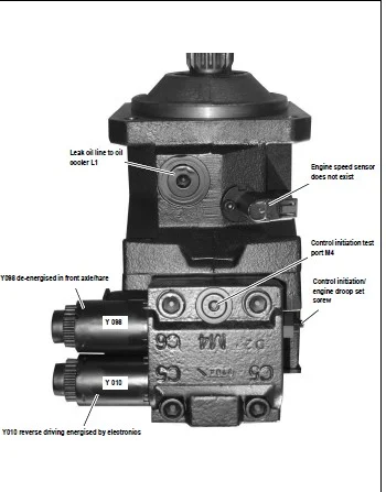
1076 List of frequencies for radio control system 10-108
1077 Specifications – work platform 10-109
1078 Inspection and maintenance work report 10-110
1079 Remote radio control (hydraulic circuit) 10-111
1080 Relays (overview) 10-112
1081 Remote radio control valves (overview) 10-113
1082 Safe load indicator 10-114
1083 Safety instructions regarding the safe load indicator 10-115
1084 Overview of displays 10-117
1085 Safe load indicator for telescopic boom (version A) 10-118
1086 Safe load indicator for telescopic boom (version B) 10-119
1087 Safe load indicator for telescopic boom (version C) 10-121
1088 Setting the safe load indicator (version C) 10-122
1089 Safe load indicator settings for telescopic boom (version B) 10-125
1090 Setting the safe load indicator (100 % point stability) 10-126
1091 Removing the load sensor 10-128
1092 Overload control in bucket mode 10-129
1093 Overload control in fork lift mode 10-130
1094 Disabling the overload control manually 10-131
1095 Adjustment work on the overload control 10-132
1096 Circuit diagram: overload control enabled 10-136
1097 Circuit diagram: overload control disabled 10-137
1098 Overview of valves 10-138
1099 Overview of valve connections and ports 10-139
10100 Circuit diagram: raising/lowering, switch S116 actuated (bucket operation) 10-140
10101 Circuit diagram: raising/lowering under 36° and at 80 – 100 % load 10-141
10102 Circuit diagram: raising/lowering over 100 % load and angle detection under 36° 10-142
10103 Circuit diagram: raising/lowering, switch S84 actuated (overload control OFF) 10-143
10104 Circuit diagram: raising/lowering, switch S125 retract (pallet forks operation) 10-144
10105 Circuit diagram: raising/lowering, switch S125 ON (bucket operation) 10-145
10106 Circuit diagram: extend telescopic boom, load less than 100 % 10-146
10107 Circuit diagram: extend telescopic boom, load over 100 % 10-147
10108 Circuit diagram: retract telescopic boom 10-148
10109 Circuit diagram: retraction/extension switch S84 (telescopic boom extension) 10-149
10110 Cab wiring harness (overload control) 10-150
10111 Legend: cab wiring harness (overload control) 10-151
10112 Frame wiring harness (overload control) 10-152
10113 Relay wiring harness (overload control) 10-153
10114 Legend: relays (overload control) 10-154
10115 Electric components (overload control) 10-155
A Appendix
A1 4-fold control valve (Bucher), fixed displacement pump (overall hydraulic diagram) A-2
A1 4-fold control valve (Bucher), variable displacement pump (overall hydraulic diagram) A-4
A2 4-fold control valve (HUSCO) (overall hydraulic diagram) A-6
A3 Hydraulics – 4-fold control valve: overall diagram A-8
A4 Fixed displacement pump – 5-fold control valve (Bucher) (overall hydraulic diagram) A-10
A5 Fixed displacement pump – 5-fold control valve (HUSCO) (overall hydraulic diagram) A-12
A6 Variable displacement pump – 5-fold control valve (Bucher) (overall hydraulic diagram) A-14
A7 Variable displacement pump – 5-fold control valve (HUSCO) (overall hydraulic diagram) A-16
IMAGES PREVIEW OF THE MANUAL:
CLAAS SCORPION 9040 (404-03) 7045 (403-03) 7040 (402-03) 7030 (401-03) 6030 (400-01) REPAIR MANUAL – PDF DOWNLOAD:
PLEASE NOTE:
- This is the SAME exact manual used by your dealers to fix your vehicle.
- The same can be yours in the next 2-3 mins as you will be directed to the download page immediately after paying for the manual.
- Any queries / doubts regarding your purchase, please feel free to contact [email protected]
S.M