Claas SCORPION – AUSTRALIA 7045 7040 7030 Operator’s Manual – PDF DOWNLOAD
Original price was: $89.00.$24.95Current price is: $24.95.
Claas SCORPION – AUSTRALIA 7045 7040 7030 Operator’s Manual – PDF DOWNLOAD
Description
Claas SCORPION – AUSTRALIA 7045 7040 7030 Operator’s Manual – PDF DOWNLOAD
DESCRIPTION:
Claas SCORPION – AUSTRALIA 7045 7040 7030 Operator’s Manual – PDF DOWNLOAD
1 Introduction
1.1 Operator’s Manual
Important notice on this Operator’s Manual
- This Operator’s Manual applies to the telehandler models 401-03, 402-03 and 403-03 It is primarily designated for the operator and provides instructions on the use, the adjustment, the operation and the maintenance of the machine. Carefully read and understand the Operator’s Manual before starting up, servicing or repairing the machine. Pay particular
- attention to the “Safety Instructions” given in chapter 2. The Operator’s Manual must always be at hand at the place of use of the machine, and must therefore be kept in the storage compartment or net behind the seat. Immediately replace an incomplete or illegible Operator’s Manual with a new one. In addition to the Operator’s Manual, observe and instruct the
- operator in all other generally applicable legal and other mandatory regulations relevant to accident prevention and environmental protection. CLAAS keep abreast of the latest technical developments and constantly improve their products. For this reason, we may from time to time need to make changes to diagrams and descriptions in this documentation which
- do not reflect products which have already been delivered and which will not be implemented on these machines. Technical data, dimensions and weights are given as an indication only. Responsibility for errors or omissions not accepted. Please contact your dealer if you require more information on the machine or the Operator’s Manual.
TABLE OF CONTENTS:
Claas SCORPION – AUSTRALIA 7045 7040 7030 Operator’s Manual – PDF DOWNLOAD
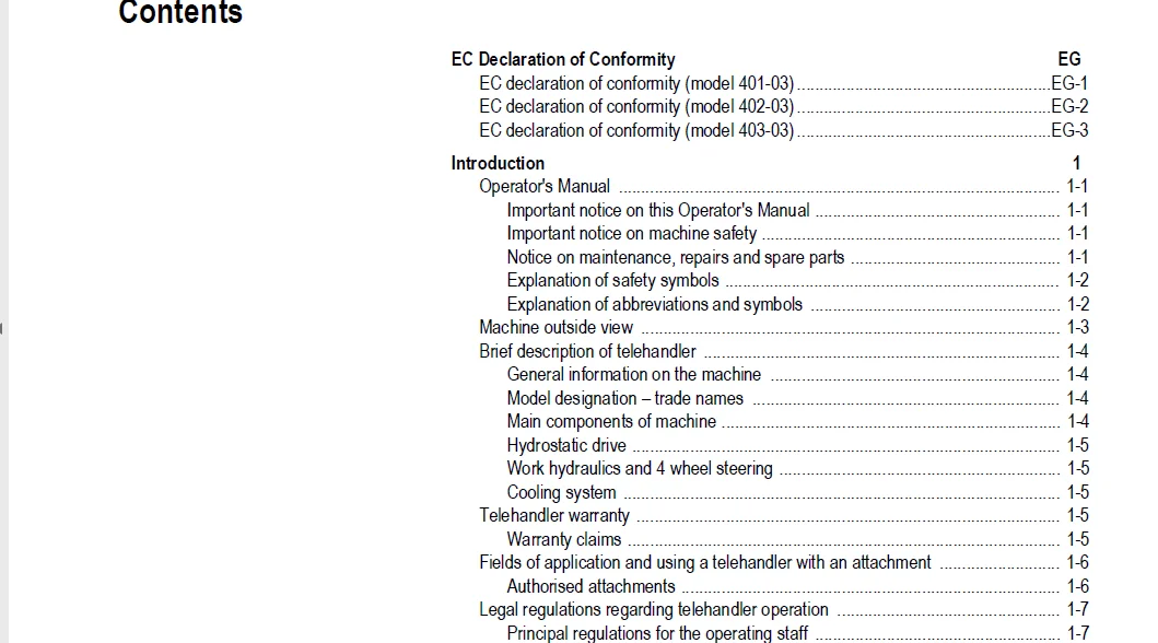
EC Declaration of Conformity EG
EC declaration of conformity (model 401-03) EG-1
EC declaration of conformity (model 402-03) EG-2
EC declaration of conformity (model 403-03) EG-3
Introduction 1
Operator’s Manual 1-1
Important notice on this Operator’s Manual 1-1
Important notice on machine safety 1-1
Notice on maintenance, repairs and spare parts 1-1
Explanation of safety symbols 1-2
Explanation of abbreviations and symbols 1-2
Machine outside view 1-3
Brief description of telehandler 1-4
General information on the machine 1-4
Model designation – trade names 1-4
Main components of machine 1-4
Hydrostatic drive 1-5
Work hydraulics and 4 wheel steering 1-5
Cooling system 1-5
Telehandler warranty 1-5
Warranty claims 1-5
Fields of application and using a telehandler with an attachment 1-6
Authorised attachments 1-6
Legal regulations regarding telehandler operation 1-7
Principal regulations for the operating staff 1-7
Driving licence 1-7
Licence/identification 1-7
Adjusting the headlights 1-8
Machine inspections 1-8
Documents 1-8
On-board equipment 1-9
Warning identification of telehandler on public roads (option) 1-9
Type labels and component numbers 1-10
Explanation of “Book” symbol 1-10
Serial number 1-10
Cab number 1-10
Engine number 1-11
Hydraulic pump number 1-11
Variable displacement motor number 1-11
Variable displacement motor number (high speed option) 1-12
Front and rear axle numbers 1-12
Description of labels 1-13
Important notice on signs and labels 1-13
Labels on the outside of the machine 1-13
Labels inside the cab 1-15
Labels in the engine compartment 1-20
Safety instructions 2
Identification of warnings and dangers 2-1
Designated use and exemption from liability 2-2
General conduct and safety instructions 2-3
Organisational measures 2-3
Selection and qualification of staff, basic responsibilities 2-5
Safety instructions regarding operation 2-6
Normal operation 2-6
Contents
I-2 00 0291 934 0 – BA SCORPION – AUSTRALIA
Contents
Applications with lifting gear 2-8
Trailer operation 2-8
Attachment operation 2-9
Transport 2-9
Safety instructions for maintenance 2-10
Maintenance work on protective ROPS and FOPS structures 2-12
ROPS/FOPS description 2-12
Cab, roll-over bar, protective screen 2-12
Warning of special hazards 2-12
Electric energy 2-12
Gas, dust, steam, smoke 2-13
Hydraulic equipment 2-13
Noise 2-13
Oil, grease and other chemical substances 2-13
Battery 2-14
Tyres 2-14
Operation 3
Information regarding the description of the control elements 3-1
Inside of cab (overview) 3-2
Control elements on the control lever and switch consoles: overview 3-4
Indicator lights and warning lights: description 3-6
Indicator light check 3-6
Indicator light and warning light – indicating instrument 3-6
Indicator light and warning light – front instrument panel 3-8
Before putting the machine into operation 3-9
Important information for the operating staff 3-9
Running-in period 3-9
“Diesel engine start” checklist 3-10
Checklist “Putting the machine into service” 3-11
“Parking” checklist 3-11
Cab 3-12
Safety instructions regarding cab entrance and exit 3-12
Safety instruction – side window (right) 3-12
Locking and unlocking the door 3-13
Closing and opening the side window (to a gap) 3-14
Completely opening and locking the side window 3-14
Opening/closing the rear window 3-15
Rear window emergency exit 3-15
Seat 3-16
Important notice on seat adjustment 3-16
Seat adjustment: overview 3-16
Weight adjustment 3-17
Backrest adjustment 3-17
Horizontal adjustment 3-17
Lumbar support adjustment (option) 3-18
Adjustment of horizontal suspension (option) 3-18
Adjustable seat suspension damper (option) 3-18
Heated seat (option) 3-18
Seat belt (lap belt) 3-19
Important notice on the seat belt 3-19
Fastening the seat belt 3-19
Unfastening the seat belt 3-20
Longer/shorter lap belt adjustment: 3-20
Engine cover 3-20
Opening/closing the engine cover 3-20
Air-suspension seat (option) 3-21
00 0291 934 0 – BA SCORPION – AUSTRALIA I-3
Contents
Important notice on air-suspension seat operation 3-21
Air-suspension seat operation 3-21
Fire extinguisher (option) 3-21
Fire extinguisher operation 3-21
Key-based drive interlock (option) 3-22
Coding (“training”) new ignition keys 3-22
Enabling (locking) the drive interlock 3-23
Disabling (releasing) the drive interlock 3-23
Deleting coded keys 3-23
Safety functions 3-23
Drive interlock with code input (option) 3-24
Entering/changing the personal code 3-25
Enabling the drive interlock 3-25
Disabling the drive interlock 3-26
Putting the drive interlock out of operation 3-26
Putting the drive interlock back into operation again 3-27
Interruption of drive interlock power 3-27
Drive interlock maintenance 3-27
Battery master switch 3-27
Switching the battery master switch ON and OFF 3-27
Oil and fuel preheater (option) 3-28
Putting the coolant and oil preheater into operation 3-28
Fuel preheater (option) 3-28
Putting the diesel engine into operation 3-29
Preparing to start the engine 3-29
Starting the diesel engine 3-30
Avoiding running the engine under low-load conditions 3-31
Stopping the engine 3-31
Jump-starting the engine (external battery) 3-32
Safety instructions regarding external starting aids 3-32
Providing external starting aid 3-32
Error code displays (103 kW diesel engine) 3-33
Reading out the flash code 3-33
Warning limit – coolant temperature 3-33
Warning limit – charge-air temperature 3-34
Warning limit – engine oil pressure 3-34
Overview – description of flashing codes 3-35
Preparing for driving on public roads 3-38
Important notice regarding driving on public roads 3-38
Safety equipment for driving on public roads 3-39
Functional check of brakes, steering system and lights 3-39
Locking the control lever (joystick) and the 3rd control circuit (attachments) 3-39
Moving off the telehandler 3-40
Speed range selection 3-40
Driving direction selection (reversing operation forwards/reverse) 3-41
Selecting a speed range (low-speed control option) 3-42
Stopping/parking the machine 3-43
Steering system 3-44
Steering column height and angle adjustment 3-44
Checking the steering system 3-44
Synchronising the steering system 3-45
Changeover to front axle steering 3-46
Changing over to 4 wheel steering 3-46
Changing over to diagonal steering (crab steering option) 3-47
Accelerator pedal 3-48
Manual throttle (option) 3-48
Manual throttle operation 3-48
I-4 00 0291 934 0 – BA SCORPION – AUSTRALIA
Contents
Brake/inching pedal 3-49
Important notice on brake/inching pedal actuation 3-49
Inching with the brake/inching pedal 3-49
Braking with the brake/inching pedal 3-49
Parking brake 3-50
Notice on the parking brake 3-50
Applying the parking brake 3-50
Telescopic boom load stabiliser 3-51
Information regarding the load stabiliser function 3-51
Switching the load stabiliser ON or OFF 3-52
Differential lock 3-53
Important information on the differential lock 3-53
Switching the differential lock ON and OFF 3-53
Backup warning system (option) 3-54
Information on the backup warning system 3-54
Electric mirror adjustment (option) 3-54
Adjusting the rearview mirror 3-54
Reversing fan (option) 3-54
Machine lights 3-55
Notice on machine lights 3-55
Machine lights operation 3-55
Working lights operation 3-56
Interior light operation (cab) 3-56
Signalling system 3-57
Turn indicator operation 3-57
Hazard warning system operation 3-57
Rotating beacon operation (option) 3-57
Cab heating and ventilation 3-58
Description of the heating and ventilation system 3-58
Ventilation and heating in fresh-air mode 3-58
Ventilation and heating in mixed mode 3-58
Air conditioning (option) 3-59
Information on putting the air conditioning into operation 3-59
Air conditioning operation 3-59
Washer system 3-60
Washer system operation 3-60
Tank for washer system 3-60
Telescopic boom control lever: overview 3-61
Operating the control lever for the lift, tilt and push-out rams 3-61
Safe load indicator for telescopic boom 3-62
Important notice on the safe load indicator 3-62
Important notice on the safe load indicator overload display 3-63
Overview of indicator lights on overload display 3-63
Functional check of the safe load indicator 3-63
What to do when the indicator lights come on 3-64
Operating the telescopic boom 3-65
Raising/extending the telescopic boom 3-65
Retracting/lowering the telescopic boom 3-65
Emergency lowering of telescopic boom in case of diesel engine breakdown 3-66
Lower or raise as follows: 3-66
Operating and securing the 3rd control circuit 3-67
Locking and unlocking the quickhitch or an attachment 3-67
Equipping the machine with a standard bucket 3-68
Pressure relief on the quickhitch couplers 3-68
Fitting a standard bucket onto the quickhitch 3-69
Field of application of bucket 3-69
Mounting an attachment on a quickhitch with a hydraulic lock 3-69
00 0291 934 0 – BA SCORPION – AUSTRALIA I-5
Contents
Mounting an attachment on a quickhitch with a mechanical lock 3-70
Removing a standard bucket from the quickhitch 3-71
Working with the standard bucket 3-72
Safety instructions regarding work with the bucket 3-72
Driving on public roads with a standard bucket 3-73
Moving with the bucket fully dumped out 3-73
Safety instructions for transporting material in a full bucket 3-74
Loading loose material 3-75
Loading if the material is hard to penetrate 3-75
Removing material/digging in soft soil 3-76
Removing material/digging in hard soil 3-77
Grading 3-77
Loading vehicles 3-77
Fitting pallet forks 3-78
Picking up pallet forks with the quickhitch 3-78
Removing the pallet forks from the quickhitch 3-78
Driving on public roads with the pallet forks 3-79
Pallet forks transport position without load 3-79
Working with the pallet forks 3-80
Safety instructions regarding the use of the pallet forks 3-80
Brief instructions for fork arms 3-82
Pallet forks payload 3-82
Adjusting the fork arms of the pallet forks 3-83
Description of load diagram for pallet forks and bucket 3-84
Picking up material with the pallet forks 3-85
Transporting loads with the pallet forks 3-86
“Hose burst valve” safety feature 3-87
Emergency lowering of the telescopic boom with the hose burst valve 3-87
Continuous operation of 3rd control circuit (option) 3-88
Switching continuous operation of 3rd control circuit ON/OFF 3-88
Tilt ram lock (option) 3-88
Switching the tilt ram lock ON and OFF 3-88
Electric changeover valve for operation of 3rd control
circuit as additional front control circuit (option) 3-89
Switching the additional control circuit ON or OFF 3-89
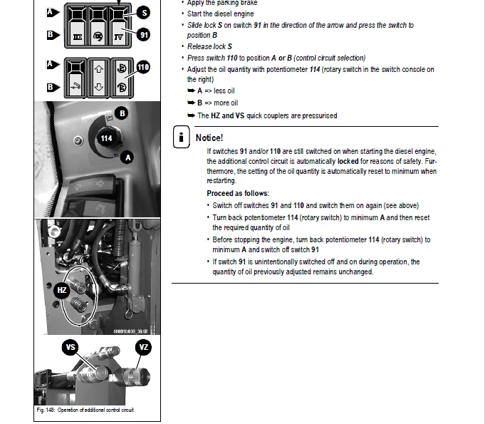
Front/rear hydraulic additional control circuit (option) 3-90
Important notice on the additional control circuit 3-90
Quick couplers of additional control circuit (overview) 3-90
Connecting an attachment onto the additional control circuit 3-91
Operation of additional control circuit 3-92
Automatic bucket repositioning (option) 3-93
Switching on the automatic bucket repositioning 3-93
Tipping trailer connection (option) 3-93
Tipping trailer connection (overview and operation) 3-93
Operation of the Autohitch trailer coupling (option) 3-94
Notice on the Autohitch trailer coupling 3-94
Unlocking and opening the Autohitch trailer coupling 3-94
Locking the Autohitch trailer coupling 3-95
Automatic trailer coupling (option) 3-96
Notice on using the trailer coupling 3-96
Attaching a trailer 3-96
Uncoupling the trailer 3-97
Compressed-air brake system (option) 3-98
Important safety instructions regarding the compressed-air braking system 3-98
Coupling and uncoupling compressed-air hoses 3-98
Compressed-air gauge 3-99
Hydraulic trailer brake (option) 3-99
I-6 00 0291 934 0 – BA SCORPION – AUSTRALIA
Contents
Notice on using the hydraulic trailer brake 3-99
Fitting attachments other than Kramer onto the quickhitch (option) 3-100
Quickhitches for attachments from other manufacturers 3-100
Important notice on fitting attachments from other manufacturers 3-100
Fitting attachments from other manufacturers 3-101
Example: inspection plan for attachments other than Kramer 3-102
Mounting hydraulic attachments from other manufacturers 3-103
Important notice on mounting 3-103
Mounting an attachment from another manucturer on the quickhitch 3-103
Hydraulic connections: attachments from other manufacturers
on the 3rd control circuit (example) 3-104
Removing attachments from other manufacturers from the quickhitch 3-105
Towing the machine 3-106
Safety instructions for towing away 3-106
Getting ready for towing 3-106
Towing the machine 3-107
Once towing is over 3-107
Loading and transporting the machine on a transport vehicle 3-108
Safety instructions regarding loading 3-108
Loading and tying down the machine 3-109
Tying down the machine 3-109
Crane handling the machine 3-110
Safety instructions regarding crane handling 3-110
Crane handling 3-111
Decommissioning the machine for a longer time 3-112
Preserving the piston rods of the hydraulic rams 3-112
Preserving the diesel engine 3-112
Final decommissioning of machine 3-113
Information on decommissioning 3-113
Preparing disposal 3-113
Disposal 3-113
Troubleshooting 4
Diesel engine malfunctions 4-1
Malfunctions in the air conditioning system (option) 4-3
Maintenance 5
Important information on maintenance work 5-1
Maintenance staff 5-1
Important safety instructions on maintenance work 5-1
Safety prop for telescopic boom 5-2
Mounting the safety prop 5-2
Fuel system 5-3
General safety instructions for refuelling 5-3
Diesel fuel specification 5-3
Stationary fuel pumps 5-3
Refuelling 5-4
Bleeding the fuel system 5-4
Checking/replacing the fuel prefilter (water separator) 5-5
Replacing the fuel filter 5-6
Cleaning the fuel cooler (option) 5-6
Diesel engine lubrication system 5-7
Important safety instructions for working on the lube oil system 5-7
Checking the engine oil level daily 5-7
Filling up engine oil 5-8
Replacing the engine oil (every 500 service hours) 5-9
Replacing the engine oil filter (every 500 service hours) 5-10
Engine and hydraulics cooling system 5-11
00 0291 934 0 – BA SCORPION – AUSTRALIA I-7
Contents
Safety instructions regarding cooling system maintenance 5-11
Notice on inspection and cleaning work 5-11
Temperature gauge: diesel engine coolant 5-12
Checking the coolant level and quality 5-12
Filling up coolant 5-13
Draining coolant 5-14
Cleaning the radiator fins 5-15
Cleaning the radiator with the reversing fan (option) 5-16
Air filter 5-17
Checking air filter contamination 5-17
Checking the dust collector (option) once a day 5-18
Replacing the filter cartridge at 500 s/h (service hours) 5-18
V-belts 5-19
Checking the V-belts 5-19
Retightening the V-belts 5-19
Hydraulic system 5-20
Specific safety instructions regarding the hydraulic system 5-20
Important notice on hydraulic oil 5-20
Monitoring the hydraulic oil and the return filter 5-21
Checking the hydraulic oil level once a day 5-22
Filling up hydraulic oil 5-22
Important notice regarding the use of biodegradable oil 5-23
Checking hydraulic pressure lines 5-24
Safety instructions regarding pressure line checks 5-24
Notice for the entrepreneur/owner 5-24
Lubrication work 5-25
Preparing lubrication 5-25
Lubricating the rear axle oscillation-type bearing 5-25
Lubricating the planetary drive bearing (front and rear axles) 5-25
Lubrication points on the telescopic boom: overview 5-26
Description of lubrication points 5-26
Lubricating the telescopic boom 5-27
Checking and adjusting the slide plates 5-27
Lubricating with the central lubrication system (option) 5-28
General functional description of the central lubrication system 5-28
Time control 5-28
Repair work 5-28
Setting the lubrication and break times 5-29
Filling the central lubrication system 5-29
Maintenance of the brake system 5-30
Important safety instructions regarding the brake system 5-30
Checking/filling up the brake fluid level 5-30
Maintenance: compressed-air brake system (option) 5-31
Checking the compressed-air tank and lines 5-31
Checking compressor attachment and drive 5-31
Tyres 5-32
Daily tyre checks 5-32
Changing wheels 5-33
Heating and ventilation system maintenance 5-34
General information on the heating system 5-34
Cleaning/replacing the fine-dust filter 5-34
Cleaning/replacing the recirculated-air filter 5-34
Air conditioning (option): maintenance 5-35
Safety instructions regarding the air conditioning 5-35
Filling up the air conditioning system 5-35
Checking the function, visual check and cleaning once a day 5-36
Maintenance of the electrical system 5-37
I-8 00 0291 934 0 – BA SCORPION – AUSTRALIA
Contents
Important notice 5-37
Safety instructions regarding the electrical system and the battery 5-37
Checking/replacing the battery 5-38
Checks at regular intervals 5-39
Alternator 5-39
Checking/replacing relays and fuses 5-39
Main fuse box with switching relays 5-40
Maintenance of the automatic trailer coupling (option) 5-41
Cleaning and lubricating the trailer coupling 5-41
Check the trailer coupling for wear 5-41
Cleaning and maintenance work 5-42
Specific safety instructions regarding cleaning 5-42
Cleaning inside the cab 5-43
Cleaning the seat belt 5-43
Cleaning the exterior of the machine 5-43
Cleaning the engine and the engine compartment 5-44
Checking screw connections 5-44
Checking pivots and hinges 5-44
Maintenance of attachments and of the work equipment 5-44
Maintenance work “Aggressive Media” (option) 5-45
Important notice on anticorrosion protection 5-45
Components coated with anticorrosive wax 5-45
Measures for maintaining anticorrosive protection 5-46
Applying the protective anticorrosion coating 5-47
Treatment of oxidised surfaces 5-47
Maintenance plan (overview) 5-48
Fluids and lubricants 5-53
Maintenance label 5-54
Explanation of symbols on the maintenance label 5-54
Maintenance label overview 5-55
Specifications 6
Model and trade names: overview 6-1
Frame 6-1
Engine 6-1
Oil/water fan 6-2
Power train 6-2
Variable displacement pump 6-2
Variable displacement motor 6-2
Axles 6-3
Front axle 6-3
Rear axle 6-3
Service and parking brake 6-4
Steering system 6-4
Work hydraulics 6-5
Hydraulic pump 6-5
Hydraulic ram protection 6-5
Lift, tilt and push-out rams: velocity 6-5
Hydraulic pilot control 6-6
Usable consumer pressure at additional control circuit (option) 6-6
Electrical system 6-7
Fuse assignment 6-7
Electric components 6-8
Main fuse box with relays (88 kW diesel engine) 6-9
Main fuse box with relays (103 kW diesel engine) 6-9
Switching relay assignment 6-10
Tyres for models 401-03/402-03/403-03 6-11
00 0291 934 0 – BA SCORPION – AUSTRALIA I-9
Contents
Machine weights, axle loads 6-11
Noise levels 6-12
Vibrations, oscillation and acceleration value 6-12
Coolant compound table 6-12
Tightening torques 6-13
General tightening torques 6-13
Specific tightening torques 6-13
Trailer couplings: trailer weight/drawbar load 6-13
Payload: load diagram model 401-03 (without counterweight) 6-14
Payload: load diagram model 401-03 (with counterweight 2 x 150 kg) 6-15
Payload: load diagram model 402-03 (with counterweight 2 x 150 kg) 6-16
Payload: load diagram model 402-03 (with counterweight 2 x 300 kg) 6-17
Payload: model 403-03 load diagram 6-18
Dimensions with bucket 6-19
Dimensions with pallet forks 6-20
Index S
Index S-1
IMAGES PREVIEW OF THE MANUAL:
CLAAS SCORPION – AUSTRALIA 7045 7040 7030 OPERATOR’S MANUAL – PDF DOWNLOAD:
PLEASE NOTE:
- This is the SAME manual used by the dealers to troubleshoot any faults in your vehicle. This can be yours in 2 minutes after the payment is made.
- Contact us at [email protected] should you have any queries before your purchase or that you need any other service / repair / parts operators manual.
s.m