CLAAS Swather LINER 2900 LINER 2800 Electro-hydraulic individual rotor lifting function Fitting Instructions Manual_DE_EN_FR_NL_DA_IT – PDF
Original price was: $89.00.$26.95Current price is: $26.95.
CLAAS Swather LINER 2900 LINER 2800 Electro-hydraulic individual rotor lifting function Fitting Instructions Manual_DE_EN_FR_NL_DA_IT – PDF
Anbauanleitung
Elektro-hydraulischer Kreisel-
Einzelaushub
Fitting Instructions
Electro-hydraulic individual rotor
lifting function
Notice de montage
Relevage individuel électrohydraulique
de toupie
Montage-handleiding
Elektrohydraulisch gescheiden
tolhefmechanisme
Monteringsvejledning
El-hydraulisk enkelthævning af
rivehjul
Istruzioni di montaggio
Sollevamento elettroidraulico singolo
della girante
Description
CLAAS Swather LINER 2900 LINER 2800 Electro-hydraulic individual rotor lifting function Fitting Instructions Manual_DE_EN_FR_NL_DA_IT – PDF
DESCRIPTION:
CLAAS Swather LINER 2900 LINER 2800 Electro-hydraulic individual rotor lifting function Fitting Instructions Manual_DE_EN_FR_NL_DA_IT – PDF
Anbauanleitung
Elektro-hydraulischer Kreisel-
Einzelaushub
Fitting Instructions
Electro-hydraulic individual rotor
lifting function
Notice de montage
Relevage individuel électrohydraulique
de toupie
Montage-handleiding
Elektrohydraulisch gescheiden
tolhefmechanisme
Monteringsvejledning
El-hydraulisk enkelthævning af
rivehjul
Istruzioni di montaggio
Sollevamento elettroidraulico singolo
della girante
1.1 Allgemeine Hinweise
1.1.1 Handhabung der Anleitung
- Die vorliegende Anleitung zeigt Ihnen die Montage der in Kapitel Lieferumfang aufgeführten Teile. Beachten Sie auch, dass in den nachfolgenden Kapitel der CLAAS Wirbelschwader auch Maschine genannt wird. Texte und Bilder sind nach Möglichkeit neutral gehalten. Auf Unterschiede wird durch Bildüberschriften oder Texthinweise aufmerksam gemacht.
- Vor Beginn der Arbeiten feststellen, ob alle Werkzeuge und Hilfsmittel vorhanden sind. Ein Vergleich zwischen dem vorhandenen Maschinentyp/Vorsatztyp, der Aufstellung im Abschnitt »Lieferumfang« und des gelieferten Teilesatzes durchführen. Die Spezifikation der Teile, z. B. bei Schrauben, entnehmen Sie bitte der Auflistung »Lieferumfang«.
- In dieser Auflistung bekommt jedes Anbauteil eine Positionsnummer (Pos.-Nr.). Weitere Angaben zu den Teilen sind die Ersatzteil-Nr., die Anzahl, die Abmessung, die ISO/DIN und die Verwendung. Bei den Montagebeschreibungen werden zur besseren Orientierung vorhandene Teile mit Buchstaben und Neuteile mit Zahlen gekennzeichnet. Positionsangaben wie
- vorn, hinten, rechts und links gelten immer in Fahrtrichtung. Technische Angaben, Maße und Gewichte verstehen sich mit entsprechenden Toleranzen. Änderungen im Zuge der technischen Entwicklung und Irrtümer vorbehalten.
1.1 General Information
1.1.1 How to use this manual
- The present manual shows you how to install the parts listed in the “Shipping package” chapter. Please observe that in the chapters below, the CLAAS rotary swather will also be referred to as machine. Texts and pictures apply to all models as far as possible. Differences are referred to in captions to the pictures or in the main text. Before starting work, ensure that all
- tools and auxiliary devices are available. Compare the existing type of machine/front attachment with the list in the “Shipping package” chapter and with the parts delivered. For specifications of parts, e.g. of bolts, please refer to the “Shipping package” list. In that list, every component has an item no. Further details relating to the components include the
- part no., the quantity, the dimension, ISO/DIN standards and their use. To make the installation instructions easier to understand, existing parts are marked by letters whereas new parts are marked by numbers. Front, rear, right and left always refer to the direction of forward travel. Technical specifications, dimensions, and weights are understood with the usual tolerances. CLAAS reserves the right to make subsequent changes in the course of technical developments.
1.1 Conseils généraux
1.1.1 Utilisation de la notice
- La présente notice vous explique le montage des pièces répertoriées au chapitre Pièces fournies. Au cours des chapitres suivants, l’andaineur CLAAS sera également appelé machine. Dans la mesure du possible, les textes et les illustrations sont neutres. Les différences sont marquées par des légendes au niveau de l’illustration et des remarques dans le texte.
- Avant le début du travail, s’assurer que tous les outils et dispositifs sont à disposition. Faire une comparaison entre le type machine/le type d’outil frontal existant, la liste de la section »Pièces fournies« et le jeu de pièces fourni. La spécification des pièces par ex. pour les vis, figure sur la liste »Pièces fournies«.
- Chaque composant de cette liste est doté d’un numéro de position (N° Pos.). Les autres données concernant ces pièces sont le N° de pièce de rechange, la quantité, les dimensions, la norme ISO/DIN et l’utilisation. Pour faciliter la compréhension au niveau des descriptions de montage, les pièces existantes sont marquées par des lettres et les nouvelles pièces par des chiffres.
- Les indications de position, telles que avant, arrière, droite et gauche sont toujours valables dans le sens de l’avancement. Les caractéristiques techniques, dimensions et poids sont sans engagement. CLAAS se réserve le droit d’apporter des modifications dans le cadre du progrès technique
TABLE OF CONTENTS:
CLAAS Swather LINER 2900 LINER 2800 Electro-hydraulic individual rotor lifting function Fitting Instructions Manual_DE_EN_FR_NL_DA_IT – PDF
DE
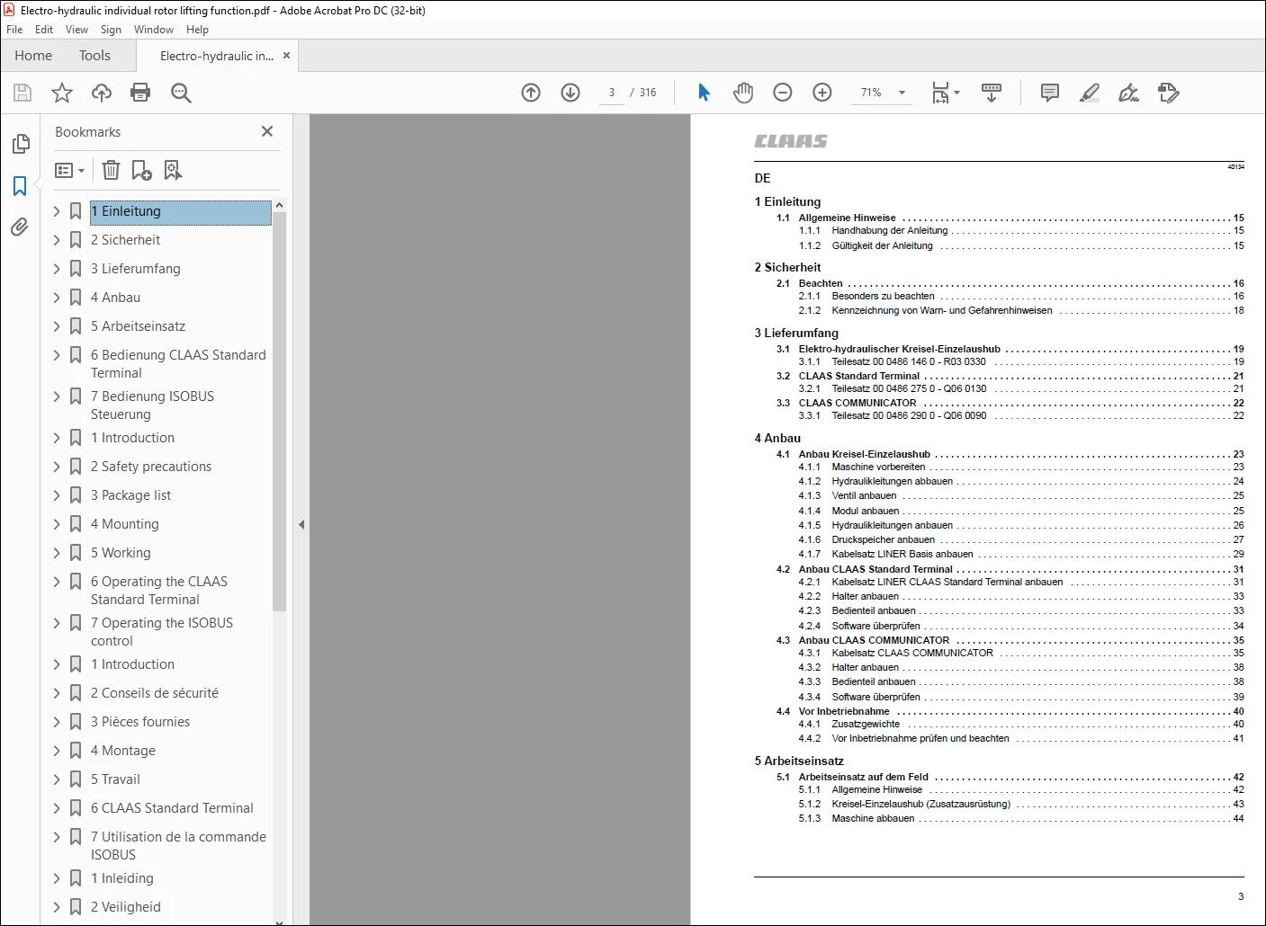
1 Einleitung
11 Allgemeine Hinweise 15
111 Handhabung der Anleitung 15
112 Gültigkeit der Anleitung 15
2 Sicherheit
21 Beachten 16
211 Besonders zu beachten 16
212 Kennzeichnung von Warn- und Gefahrenhinweisen 18
3 Lieferumfang
31 Elektro-hydraulischer Kreisel-Einzelaushub 19
311 Teilesatz 00 0486 146 0 – R03 0330 19
32 CLAAS Standard Terminal 21
321 Teilesatz 00 0486 275 0 – Q06 0130 21
33 CLAAS COMMUNICATOR 22
331 Teilesatz 00 0486 290 0 – Q06 0090 22
4 Anbau
41 Anbau Kreisel-Einzelaushub 23
411 Maschine vorbereiten 23
412 Hydraulikleitungen abbauen 24
413 Ventil anbauen 25
414 Modul anbauen 25
415 Hydraulikleitungen anbauen 26
416 Druckspeicher anbauen 27
417 Kabelsatz LINER Basis anbauen 29
42 Anbau CLAAS Standard Terminal 31
421 Kabelsatz LINER CLAAS Standard Terminal anbauen 31
422 Halter anbauen 33
423 Bedienteil anbauen 33
424 Software überprüfen 34
43 Anbau CLAAS COMMUNICATOR 35
431 Kabelsatz CLAAS COMMUNICATOR 35
432 Halter anbauen 38
433 Bedienteil anbauen 38
434 Software überprüfen 39
44 Vor Inbetriebnahme 40
441 Zusatzgewichte 40
442 Vor Inbetriebnahme prüfen und beachten 41
5 Arbeitseinsatz
51 Arbeitseinsatz auf dem Feld 42
511 Allgemeine Hinweise 42
512 Kreisel-Einzelaushub (Zusatzausrüstung) 43
513 Maschine abbauen 44
4
40134
6 Bedienung CLAAS Standard Terminal
61 Beschreibung 45
611 Übersicht 45
612 Kennzeichnung der Tasten 45
62 Funktionsweise 46
621 Ein/Aus 46
622 Vorwahl Arbeitsstellung 47
623 Vorwahl Arbeitsbreite 47
624 Vorwahl Kreisel-Einzelaushub (Zusatzausrüstung) 48
625 Vorwahl Rechhöhe (Zusatzausrüstung) 49
626 Vorwahl Transportstellung 50
7 Bedienung ISOBUS Steuerung
71 Einleitung 51
711 Beschreibung 51
712 Handhabung der Anleitung 51
713 Erläuterungen zu ISOBUS-Begriffen 51
72 Übersicht 53
721 Bildschirm 53
722 Titelleiste 53
723 Menüleiste 53
724 Softkey 54
725 Statusleiste 55
726 Datenfeld 56
727 Programm-Version 56
73 Erste Schritte 57
731 Steuerungsprogramm starten 57
74 Bedienung der Maschine 59
741 Transportstellung 59
742 Arbeitsstellung 59
743 Arbeitseinsatz im Feld 61
744 Vorwahl Rechhöhe (Zusatzausrüstung) 63
5
40134
EN
1Introduction
11 General Information 65
111 How to use this manual 65
112 Validity of instructions 65
2 Safety precautions
21 Important 66
211 Important information 66
212 Identification of warning and danger signs 68
3 Package list
31 Electro-hydraulic individual rotor lifting function 69
311 Parts kit 00 0486 146 0 – R03 0330 69
32 CLAAS standard terminal 71
321 Parts kit 00 0486 275 0 – Q06 0130 71
33 CLAAS COMMUNICATOR 72
331 Parts kit 00 0486 290 0 – Q06 0090 72
4 Mounting
41 Attaching the individual rotor lift 73
411 Preparing the machine 73
412 Removing the hydraulic lines 74
413 Installing the valve 74
414 Installing the module 75
415 Attaching the hydraulic lines 75
416 Installing the accumulator 76
417 Installing the LINER base wiring loom 78
42 Installing the CLAAS standard terminal 80
421 Installing the LINER CLAAS standard terminal wiring loom 80
422 Fitting the bracket 82
423 Attaching the control unit 82
424 Check software 83
43 Installing the CLAAS COMMUNICATOR 84
431 CLAAS COMMUNICATOR wiring loom 84
432 Fitting the bracket 87
433 Attaching the control unit 87
434 Check software 88
44 Before putting the machine into operation 89
441 Additional weights 89
442 Items to check and observe before operation 90
5 Working
51 Working in the field 91
511 General information 91
512 Individual rotor lift 92
513 Unhitching the machine 93
6
40134
6 Operating the CLAAS Standard Terminal
61 Description 94
611 Presentation 94
612 Key identification 94
62 Operation 95
621 On/Off 95
622 Working position preselection 96
623 Working width preselection 96
624 Individual rotor lifting function preselection (accessory) 97
625 Raking height preselection (accessory) 98
626 Transport position preselection 99
7 Operating the ISOBUS control
71 Introduction 100
711 Description 100
712 Using the manual 100
713 Explanations of ISOBUS terminology 100
72 Overview 102
721 Monitor 102
722 Title bar 102
723 Menu bar 102
724 Softkey 103
725 Status bar 104
726 Data field 105
727 Program version 105
73 First steps 106
731 Starting the control program 106
74 Machine operation 108
741 Transport position 108
742 Working position 108
743 Fieldwork 110
744 Raking height preselection (accessory) 112
7
40134
FR
1Introduction
11 Conseils généraux 114
111 Utilisation de la notice 114
112 Validité de la notice 114
2 Conseils de sécurité
21 Observer 115
211 Important 115
212 Marquage des avertissements et des dangers 117
3 Pièces fournies
31 Relevage individuel électro-hydraulique de toupie 118
311 Jeu de pièces 00 0486 146 0 – R03 0330 118
32 Terminal standard CLAAS 120
321 Jeu de pièces 00 0486 275 0 – Q06 0130 120
33 CLAAS COMMUNICATOR 121
331 Jeu de pièces 00 0486 290 0 – Q06 0090 121
4 Montage
41 Montage du relevage individuel des toupies 122
411 Préparation de la machine 122
412 Dépose des flexibles hydrauliques 123
413 Poser la vanne 124
414 Poser le module 124
415 Montage des flexibles hydrauliques 125
416 Pose de l’accumulateur de pression 126
417 Pose du jeu de câbles LINER Basis 128
42 Pose du terminal standard CLAAS 131
421 Poser le jeu de câbles du terminal standard LINER CLAAS 131
422 Poser le support 133
423 Montage de l’élément de commande 133
424 Vérifier le logiciel 134
43 Pose du COMMUNICATOR CLAAS 135
431 Jeu de câbles COMMUNICATOR CLAAS 135
432 Poser le support 138
433 Montage de l’élément de commande 138
434 Vérifier le logiciel 139
44 Avant la mise en service 140
441 Lests supplémentaires 140
442 Avant la mise en service de la machine, vérifier les points suivants 141
5 Travail
51 Travail dans le champ 142
511 Conseils généraux 142
512 Relevage individuel des toupies 143
513 Dépose de la machine 144
8
40134
6 CLAAS Standard Terminal
61 Descriptif 145
611 Présentation 145
612 Identification des touches 145
62 Fonctionnement 146
621 Marche/Arrêt 146
622 Présélection position de travail 147
623 Présélection de la largeur de travail 147
624 Présélection de relevage individuel de toupie (équipement supplémentaire) 148
625 Présélection de la hauteur de ratissage (équipement supplémentaire) 149
626 Présélection position de route 150
7 Utilisation de la commande ISOBUS
71 Introduction 151
711 Description 151
712 Utilisation de la notice 151
713 Explications concernant les termes ISOBUS 151
72 Vue d’ensemble 153
721 Ecran 153
722 Barre de titre 153
723 Barre de menu 153
724 Softkey (touche programmable) 154
725 Barre d’état 155
726 Champ de données 156
727 Version du programme 156
73 Premières étapes 157
731 Lancer le programme de gestion 157
74 Utilisation de la machine 159
741 Position de transport 159
742 Position de travail 159
743 Travail dans le champ 161
744 Présélection de la hauteur de ratissage (équipement supplémentaire) 163
9
40134
NL
1Inleiding
11 Algemene aanwijzingen 165
111 Gebruik van de handleiding 165
112 Geldigheid van de handleiding 165
2 Veiligheid
21 In acht nemen 166
211 Let vooral op het volgende 166
212 Aanduiding van waarschuwings- en gevarenindicaties 168
3 Leveringsomvang
31 Elektrohydraulisch gescheiden tolhefmechanisme 169
311 Onderdelenset 00 0486 146 0 – R03 0330 169
32 Standaard CLAAS-terminal 171
321 Onderdelenset 00 0486 275 0 – Q06 0130 171
33 CLAAS COMMUNICATOR 172
331 Onderdelenset 00 0486 290 0 – Q06 0090 172
4 Montage
41 Montage gescheiden tolhefmechanisme 173
411 Machine voorbereiden 173
412 Hydraulische leidingen demonteren 174
413 Ventiel monteren 175
414 Module monteren 175
415 Hydraulische leidingen monteren 176
416 Drukbollen monteren 177
417 Kabelset LINER Basis monteren 179
42 Montage standaard CLAAS-terminal 181
421 Kabelset LINER Standaard CLAAS-terminal monteren 181
422 Houder monteren 183
423 Bedieningselement monteren 183
424 Software controleren 184
43 Montage CLAAS COMMUNICATOR 185
431 Kabelset CLAAS COMMUNICATOR 185
432 Houder monteren 188
433 Bedieningselement monteren 188
434 Software controleren 189
44 Vóór ingebruikname 190
441 Extra gewichten 190
442 Vóór ingebruikname controleren en in acht nemen 191
5 Werkstand
51 Uitvoeren van werkzaamheden in het veld 192
511 Algemene aanwijzingen 192
512 Gescheiden tolhefmechanisme 193
513 Machine demonteren 194
10
40134
6 Standaard CLAAS-terminal
61 Beschrijving 195
611 Overzicht 195
612 Betekenis van de toetsen 195
62 Werking 196
621 Aan/Uit 196
622 Voorkeuze werkstand 197
623 Voorkeuze werkbreedte 197
624 Voorkeuze gescheiden tolhefmechanisme (extra uitrusting) 198
625 Voorkeuze harkhoogte (extra uitrusting) 199
626 Voorkeuze transportstand 200
7 Bediening ISOBUS-regeling
71 Inleiding 201
711 Beschrijving 201
712 Gebruik van de handleiding 201
713 Verklaringen van de ISOBUS-begrippen 201
72 Overzicht 203
721 Scherm 203
722 Titelbalk 203
723 Menubalk 203
724 Softkey 204
725 Statusbalk 206
726 Gegevensveld 206
727 Programmaversie 207
73 Begin 208
731 Besturingsprogramma starten 208
74 Bediening van de machine 210
741 Transportstand 210
742 Werkstand 210
743 Gebruik op het veld 212
744 Voorkeuze harkhoogte (extra uitrusting) 214
11
40134
DA
1Indledning
11 Generelle anvisninger 216
111 Anvendelse af anvisningen 216
112 Gyldighed 216
2 Sikkerhed
21 Bemærk! 217
211 Bemærk 217
212 Advarselsmarkering 219
3 Medfølgende dele
31 El-hydraulisk enkelthævning af rivehjul 220
311 Reservedelssæt 00 0486 146 0 – R03 0330 220
32 CLAAS standardterminal 222
321 Reservedelssæt 00 0486 275 0 – Q06 0130 222
33 CLAAS COMMUNICATOR 223
331 Reservedelssæt 00 0486 290 0 – Q06 0090 223
4 Montering
41 Montering af enkelthævning af rivehjul 224
411 Klargøring af maskinen 224
412 Afmontering af hydraulikslanger 225
413 Montering af ventil 226
414 Montering af modul 226
415 Afmonter hydraulikslangerne 227
416 Montering af trykakkumulator 228
417 Montering af ledningsnet LINER Basis 230
42 Montering af CLAAS standardterminal 232
421 Montering af ledningsnet LINER CLAAS standardterminal 232
422 Montering af holder 234
423 Monter betjeningsdel 234
424 Kontrol af software 235
43 Montering af CLAAS COMMUNICATOR 236
431 Ledningsnet CLAAS COMMUNICATOR 236
432 Montering af holder 239
433 Monter betjeningsdel 239
434 Kontrol af software 240
44 Før ibrugtagning 241
441 Ekstravægte 241
442 Kontrol før ibrugtagning 242
5 Arbejde
51 Arbejde på marken 243
511 Generelle anvisninger 243
512 Enkelthævning af rivehjul (Tilbehør) 244
513 Afmonter maskinen 245
12
40134
6 CLAAS standardterminal
61 Beskrivelse 246
611 Oversigt 246
612 Beskrivelse af tasterne 246
62 Funktion 247
621 Til/fra 247
622 Forvalg arbejdsstilling 248
623 Forvalg arbejdsbredde 248
624 Forvalg enkelthævning af rivehjul (ekstraudstyr) 249
625 Forvalg rivehøjde (ekstraudstyr) 250
626 Forvalg transportstilling 251
7 Betjening af ISOBUS-styring
71 Indledning 252
711 Beskrivelse 252
712 Brug af anvisningen 252
713 Forklaringer til ISOBUS-begreber 252
72 Oversigt 254
721 Skærm 254
722 Titellinje 254
723 Menulinje 254
724 Softkey 255
725 Statuslinje 256
726 Datafelt 257
727 Programversion 257
73 Første trin 258
731 Start af styringsprogram 258
74 Betjening af maskinen 260
741 Transportstilling 260
742 Arbejdsstilling 260
743 Arbejde i marken 262
744 Forvalg rivehøjde (ekstraudstyr) 264
IT
1Introduzione
11 Indicazioni generali 266
111 Applicazione del libretto d’uso 266
112 Validità del libretto d’uso 266
2 Sicurezza
21 Da osservare 267
211 Avvertenze importanti 267
212 Segnalazione di avvertimento e pericolo 269
3 Complessivo di fornitura
31 Sollevamento elettroidraulico singolo della girante 270
311 Serie dei particolari 00 0486 146 0 – R03 0330 270
32 Terminale standard CLAAS 272
321 Serie dei particolari 00 0486 275 0 – Q06 0130 272
33 CLAAS COMMUNICATOR 273
331 Serie dei particolari 00 0486 290 0 – Q06 0090 273
4 Montaggio
41 Montaggio del sollevamento singolo delle giranti 274
411 Preparazione della macchina 274
412 Smontaggio delle tubazioni idrauliche 275
413 Montaggio della valvola 276
414 Montaggio del modulo 276
415 Montaggio delle tubazioni idrauliche 277
416 Montaggio dell’accumulatore di pressione 278
417 Montaggio della matassa cavi LINER di base 280
42 Montaggio del terminale standard CLAAS 282
421 Montaggio della matassa cavi del terminale standard LINER CLAAS 282
422 Montaggio del supporto 284
423 Montaggio del dispositivo di comando 284
424 Controllare il Software 285
43 Montaggio del CLAAS COMMUNICATOR 286
431 Matassa cavi CLAAS COMMUNICATOR 286
432 Montaggio del supporto 289
433 Montaggio del dispositivo di comando 289
434 Controllare il Software 290
44 Prima della messa in campo 291
441 Zavorre supplementari 291
442 Prima della messa in esercizio, eseguire i seguenti controlli ed osservare le prescrizioni 292
5 Uso lavorativo
51 Uso lavorativo sul campo 293
511 Indicazioni generali 293
512 Sollevamento singolo delle giranti 294
513 Smontaggio della macchina 295
6 CLAAS Standard Terminal
61 Descrizione 296
611 Presentazione 296
612 Identificazione dei tasti 296
62 Funzionamento 297
621 On / Off 297
622 Preselezione posizione di lavoro 298
623 Preselezione larghezza di lavoro 298
624 Preselezione sollevamento singolo della girante (attrezzatura accessoria) 299
625 Preselezione altezza del pettine (attrezzatura accessoria) 300
626 Preselezione posizione di trasporto 301
7 Impiego della gestione ISOBUS
71 Introduzione 302
711 Descrizione 302
712 Applicazione del libretto d’uso 302
713 Spiegazioni sui termini ISOBUS 302
72 Vista 304
721 Schermo 304
722 Barra del titolo 304
723 Barra dei menù 304
724 Softkey 305
725 Barra di stato 306
726 Settore dati 307
727 Versione del programma 307
73 Prima fase 308
731 Avvio del programma di gestione 308
74 Impiego della macchina 310
741 Posizione di trasporto 310
742 Posizione di lavoro 310
743 Impiego lavorativo in campo 312
744 Preselezione altezza del pettine (attrezzatura accessoria) 314
IMAGES PREVIEW OF THE MANUAL:
PLEASE NOTE:
- This is the same manual used by the DEALERSHIPS to SERVICE your vehicle.
- The manual can be all yours – Once payment is complete, you will be taken to the download page from where you can download the manual. All in 2-5 minutes time!!
- Need any other service / repair / parts manual, please feel free to contact us at heydownloadss @gmail.com . We may surprise you with a nice offer
S.M