Claas Swathers Tedders Mower Units Repair & Adjustment Instructions Manual – PDF DOWNLOAD
Original price was: $98.95.$29.95Current price is: $29.95.
Claas Swathers Tedders Mower Units Repair & Adjustment Instructions Manual – PDF DOWNLOAD
Description
Claas Swathers Tedders Mower Units Repair & Adjustment Instructions Manual – PDF DOWNLOAD
DESCRIPTION:
Claas Swathers Tedders Mower Units Repair & Adjustment Instructions Manual – PDF DOWNLOAD
INTRODUCTION :
This manual contains general instructions on the repair of CLAAS forage harvesting equipment. It also contains information on the repair of:
– LINER reduction gear
– CLAAS rotary gear
– DISCO mower head
– CORTO direct-cut drive
Please read this manual thoroughly before starting work! Pay particular attention to the “General Information” section. The required spare parts can be found in the parts list of your forage harvesting equipment.
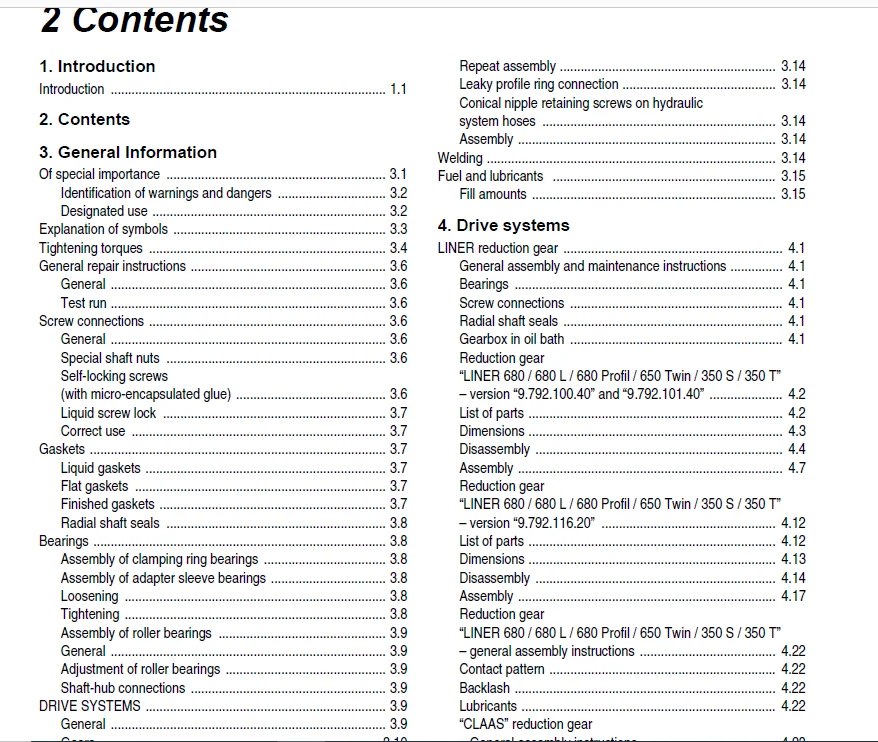
TABLE OF CONTENTS:
Claas Swathers Tedders Mower Units Repair & Adjustment Instructions Manual – PDF DOWNLOAD
1 Introduction .................................................................................................................... 3
	Introduction .................................................................................................................. 3
2 Contents ........................................................................................................................ 4
3 General Information ............................................................................................................. 6
	Of special importance ......................................................................................................... 6
		Identification of warnings and dangers .................................................................................... 7
		Designated use ............................................................................................................ 7
	Explanation of symbols ........................................................................................................ 8
	Tightening torques ............................................................................................................ 9
	General repair instructions ...................................................................................................11
		General ...................................................................................................................11
		Test run ..................................................................................................................11
	Screw connections .............................................................................................................11
		General ...................................................................................................................11
		Special shaft nuts ........................................................................................................11
		Self-locking screws (with micro-encapsulated glue) ........................................................................11
		Liquid screw lock .........................................................................................................12
			Correct use ...........................................................................................................12
	Gaskets .......................................................................................................................12
		Liquid gaskets ............................................................................................................12
		Flat gaskets ..............................................................................................................12
		Finished gaskets ..........................................................................................................12
		Radial shaft seals ........................................................................................................13
	Bearings ......................................................................................................................13
		Assembly of clamping ring bearings ........................................................................................13
		Assembly of adapter sleeve bearings .......................................................................................13
			Loosening .............................................................................................................13
			Tightening ............................................................................................................13
		Assembly of roller bearings ...............................................................................................14
			General ...............................................................................................................14
			Adjustment of roller bearings .........................................................................................14
		Shaft-hub connections .....................................................................................................14
	DRIVE SYSTEMS .................................................................................................................14
		General ...................................................................................................................14
		Gears .....................................................................................................................15
			Spur gears ............................................................................................................15
			Bevel gears ...........................................................................................................15
			Adjustment of spur gears ..............................................................................................15
			Adjustment of cyclopalloid gears ......................................................................................15
				Height adjustment of the contact pattern ..........................................................................16
				Longitudinal adjustment of the contact pattern ....................................................................17
		Tensioning steel roller chains ............................................................................................17
		Tapered ring connections ..................................................................................................18
			Disassembly ...........................................................................................................18
			Assembly ..............................................................................................................18
	Hydraulic system ..............................................................................................................18
		Ferrule retaining screws on hydraulic system hoses ........................................................................18
			Assembly ..............................................................................................................18
			Final assembly ........................................................................................................18
			Repeat assembly .......................................................................................................18
			Leaking ferrule connection ............................................................................................18
		Progressive ring retaining screws on hydraulic system hoses ...............................................................18
			Assembly ..............................................................................................................18
			Final assembly ........................................................................................................19
			Repeat assembly .......................................................................................................19
			Leaky profile ring connection .........................................................................................19
		Conical nipple retaining screws on hydraulic system hoses .................................................................19
			Assembly ..............................................................................................................19
	Welding .......................................................................................................................19
	Fuel and lubricants ...........................................................................................................20
		Fill amounts ..............................................................................................................20
4 Drive systems ...................................................................................................................21
	LINER reduction gear ..........................................................................................................21
		General assembly and maintenance instructions .............................................................................21
			Bearings ..............................................................................................................21
			Screw connections .....................................................................................................21
			Radial shaft seals ....................................................................................................21
			Gearbox in oil bath ...................................................................................................21
		Reduction gear “LINER 680 / 680 L / 680 Profil / 650 Twin / 350 S / 350 T” - version “9.792.100.40” and “9.792.101.40” ....22
			List of parts .........................................................................................................22
			Dimensions ............................................................................................................23
			Disassembly ...........................................................................................................24
			Assembly ..............................................................................................................27
		Reduction gear “LINER 680 / 680 L / 680 Profil / 650 Twin / 350 S / 350 T” - version “9.792.116.20” .......................32
			List of parts .........................................................................................................32
			Dimensions ............................................................................................................33
			Disassembly ...........................................................................................................34
			Assembly ..............................................................................................................37
		Reduction gear “LINER 680 / 680 L / 680 Profil / 650 Twin / 350 S / 350 T” - general assembly instructions ................42
			Contact pattern .......................................................................................................42
			Backlash ..............................................................................................................42
			Lubricants ............................................................................................................42
		“CLAAS” reduction gear - General assembly instructions ....................................................................43
			Installation of curved track ..........................................................................................43
			Lubricants ............................................................................................................43
	“CLAAS” rotary gearbox ........................................................................................................44
		General assembly instructions .............................................................................................44
			Assembly of the angle drive ...........................................................................................44
			Lubricants ............................................................................................................44
	DISCO cutter bar ..............................................................................................................45
		Cutter bar with 6 cutting discs “COMER FR-566A” ...........................................................................45
			Parts list “cutter bar with 6 cutting discs” ..........................................................................45
		Cutter bar with 7 cutting discs “COMER FR-567A” ...........................................................................45
			Parts list “cutter bar with 7 cutting discs” ..........................................................................46
			Parts description .....................................................................................................46
			Dimensions “cutter bar with 6 cutting discs” ..........................................................................47
			Dimensions “cutter bar with 7 cutting discs” ..........................................................................48
			Disassembly ...........................................................................................................49
		Assembly ..................................................................................................................51
			Assembling rotors .....................................................................................................52
			Assembling inlet rotor ................................................................................................53
			Replacing intermediate gear wheel - bearing ...........................................................................54
			Assembling cutter bars ................................................................................................56
			Installing rotor ......................................................................................................57
			Leak test .............................................................................................................58
			Installing slide ......................................................................................................58
			Installing cutting disc and drum ......................................................................................59
			Drum - inlet side .....................................................................................................59
		“COMER” cutter bar - General assembly instructions ........................................................................60
			Lubricants ............................................................................................................60
				Oil amount: .......................................................................................................60
				Oil change : ......................................................................................................60
	“CORTO” direct-cut attachments ................................................................................................61
		Installing direct-cut attachment ..........................................................................................61
			Lubricants ............................................................................................................61
IMAGES PREVIEW OF THE MANUAL:
CLAAS SWATHERS TEDDERS MOWER UNITS REPAIR & ADJUSTMENT INSTRUCTIONS MANUAL – PDF DOWNLOAD:
PLEASE NOTE:
- This is the same manual used by the dealers to diagnose and troubleshoot your vehicle
- You will be directed to the download page as soon as the purchase is completed. The whole payment and downloading process will take anywhere between 2-5 minutes
- Need any other service / repair / parts manual, please feel free to contact [email protected] . We still have 50,000 manuals unlisted
S.V