Claas TALOS 130-120 Repair Manual – PDF DOWNLOAD
Original price was: $78.00.$27.95Current price is: $27.95.
Claas TALOS 130-120 Repair Manual – PDF DOWNLOAD
Description
Claas TALOS 130-120 Repair Manual – PDF DOWNLOAD
DESCRIPTION:
Claas TALOS 130-120 Repair Manual – PDF DOWNLOAD
Introduction
General Information
Using this repair manual
- This repair manual will help ensure the tractor is always in full working order. Regular maintenance and upkeep, carried out by the after-sales technical department will preserve the high value of this CLAAS tractor.
- All of the expertise our after-sales technicians and the manufacturer can offer is summarised in this repair manual. The sequence of illustrations show the breakdown of a repair process. The text gives the instructions required for setting, for using the special tools and much more.
- The repair manual, as a reference document, is kept up to date with supplements and changes to meet any technical developments made to the tractor. To ensure the highest level of safety, it is essential to compare the setting values and filling volumes with those on the current manual for the corresponding tractor.
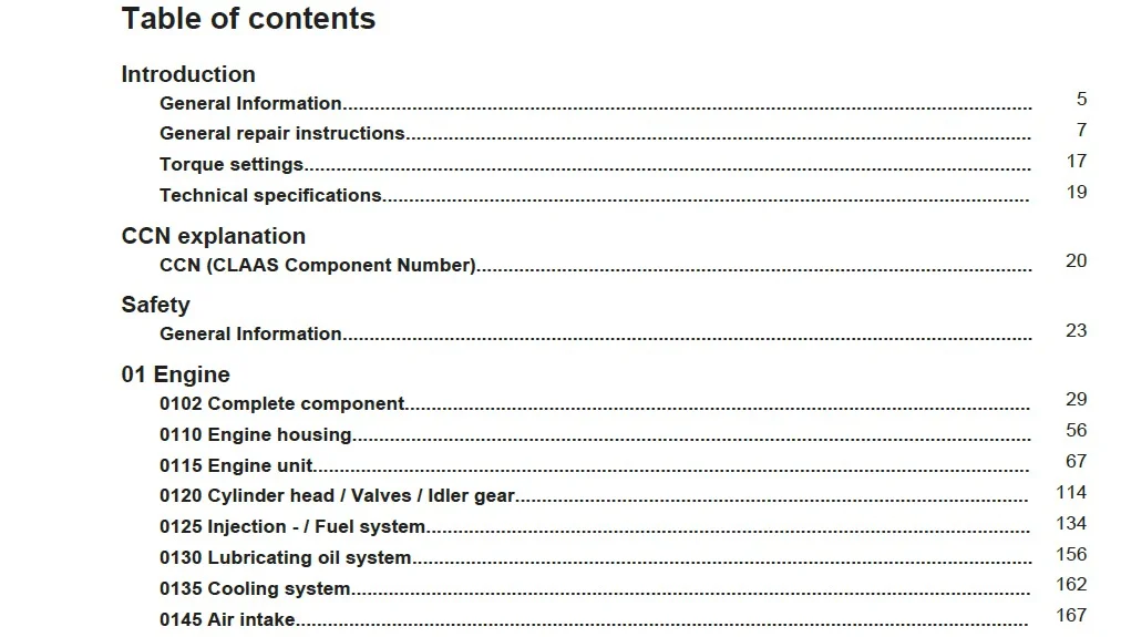
- TABLE OF CONTENTS:
Claas TALOS 130-120 Repair Manual – PDF DOWNLOAD
TALOS 130-120 1
Table of contents 3
Introduction 5
General Information 5
Using this repair manual 5
Scope of the repair manual 6
General repair instructions 7
Technical specifications 7
Cause of damage 7
Spare parts 7
Diesel engine 7
Gearbox 7
Generator 8
Welding work 8
Drive belt/drive chains 8
Tapered ring assemblies 8
Self-locking bolts with microencapsulated glue 9
Threadlock 10
Lock collar bearing 10
Collet bearing 10
Screwed unions with cutting rings on the hydraulic pipes 11
Progressive ring bolt connectors on hydraulic pipes 12
Double flare unions screwed onto the hydraulic pipes 13
Flexible hydraulic hoses 13
Advice for economical repairs 16
Torque settings 17
Tightening torques for NF E25-030-1 2007-12-01 standard metric threads 17
Technical specifications 19
Lubricants 19
CCN explanation 20
CCN (CLAAS Component Number) 20
General 20
Electric systems standard 20
Overview 20
Hydraulic system standard 20
Overview 20
B 21
R 21
S 21
T 21
Y 21
Z 22
Safety 23
General Information 23
Of special importance 23
Identification of warning and danger signs 23
General safety and accident prevention regulations 24
Leaving the machine 25
Adjustment and maintenance operations 25
Risk of injury from hydraulic fluid 26
Air conditioner 26
Hydraulic accumulators 27
First aid measures 27
Battery isolating switch 27
Jacking up the machine 28
Putting the machine out of operation 28
01 Engine 29
0102 Complete component 29
Introduction 29
General points 30
TALOS 120 engine (type S4Q) – Overview 30
TALOS 130 engine (type S4Q-T) – Overview 32
Location of the engine serial number 33
Engine model designation 33
Technical specifications 34
General instructions 35
Special tool 35
Determining when to service the engine 35
Compression measurements 36
Prerequisites 36
Compression 36
Precautions for removal and refitting 37
Removal 37
Refitting 37
Fitting lip seals, O-rings and bearings 38
Lip seals 38
O-rings 38
Bearings 39
Tests and adjustments 39
Dynamometer test (running in) 39
Starting procedure 39
Inspection after starting the engine 39
Dynamometer test conditions 40
Inspection after running in 40
Maintenance standards 40
General 40
Cylinder block 42
Main bearings 42
Pushrod bores 42
Camshaft 43
Cylinder head 43
Valves and valve guides 44
Valve seats 44
Valve springs 44
Rockers 45
Pushrods 45
Main rotating parts 45
Crankshaft 45
Pistons 46
Piston rings 46
Piston pins 47
Connecting rods 47
Flywheel 48
Timing pinions 48
Camshaft 48
Intermediate pinions 49
Clearance between teeth 49
Balancer shafts 50
Lubrication system 50
Oil pump 50
Cooling system 51
Water pump 51
Thermostat 51
Fuel supply 51
Injectors 51
Electrical system 52
Electric starting motor 52
Alternator 53
Tightening torques 53
Thread sealants 55
0110 Engine housing 56
Separating the engine from the clutch housing 56
Flywheel 62
Special tool 62
General view 63
Removing the flywheel 63
Removing the rear cover 64
Inspection 64
Flywheel and crown wheel 65
Refitting 65
Fitting the rear cover lip seal 65
Fitting the rear cover 66
Fitting the flywheel 66
Checking the surface run out and the bore run out on the flywheel pilot bearing 66
0115 Engine unit 67
Removing the timing pinions, camshaft, balancer shafts and sump 67
Overview of the assembly 67
Removing the crankshaft pulley 68
Removing the timing cover 68
Checking the clearance between the teeth 69
Checking the intermediate pinion axial play 69
Removing the intermediate pinion 69
Checking the camshaft axial play 70
Removing the sump and the gasket 70
Removing the balancer shafts 71
Removing the oil pump 72
Removing the camshaft 72
Removing the front plate 73
Inspecting the timing pinions, camshaft, balancer shafts and sump 73
Special tools 73
Checks 74
Crankshaft pulley 75
Intermediate pinion 75
Checking the clearance between the intermediate pinion and the shaft 75
Replacing the intermediate pinion ring 75
Replacing the intermediate pinion shaft 76
Camshaft 76
Checking the cam lift height 76
Checking the clearance between the camshaft journal and the bore in the cylinder block (or ring) 77
Checking the deformation 78
Removing the camshaft pinion 78
Fitting the camshaft pinion and the stop plate 78
Checking the deformation of the balancer shafts 79
Replacing the balancer shaft bearings 79
Refitting the timing pinions, camshaft, balancer shafts and sump 79
Fitting the front plate 79
Fitting the camshaft 80
Fitting the oil pump 80
Fitting the balancer shafts 81
Fitting the sump 82
Fitting the intermediate pinion 83
Checking the clearance between the teeth on the timing pinions 83
Fitting the lip seal 84
Fitting the timing cover 84
Refitting the crankshaft pulley 84
Removing the pistons, connecting rods, crankshaft and cylinder block 85
Overview of the assembly 85
Checking the clearance of the big end 86
Maximum permissible average weight difference between all the connecting rods on the same engine 87
Removing the connecting rod caps 87
Removing the pistons 88
Removing the piston rings 88
Removing the piston pins 89
Checking the crankshaft axial play 89
Removing the main bearings 90
Removing the crankshaft 90
Inspecting the pistons, connecting rods, crankshaft and cylinder block 91
Checks 91
Pistons, rings and pins 92
Checking the piston diameter 92
Checking the pistons and piston rings 93
Checking the clearance between the ends of the piston rings 94
Checking the clearance between the piston pin and the bore 94
Checking the clearance between the connecting rod ring and the piston pin 95
Replacing the connecting rod rings 95
Checking the connecting rods 95
Crankshaft 96
Checking the lubrication clearance of the connecting rod bearing shells 96
Checking the lubrication clearance for the main bearings 98
Checking the rotating surface of the lip seal 99
Checking the run out100
Removing the crankshaft pinion101
Fitting the crankshaft pinion101
Fitting the crankshaft balancer shaft drive pinion101
Cylinder block102
Checking the bores102
Checking the top surface102
Pushrods103
Checking wear103
Checking the clearance between the pushrod and the bore103
Refitting the pistons, connecting rods, crankshaft and cylinder block104
Special tool104
Fitting the pushrods104
Fitting the crankshaft104
Refitting the piston pins106
Refitting the piston rings107
Refitting the pistons108
Fault finding111
Faults and solutions113
0120 Cylinder head / Valves / Idler gear114
Removing the cylinder head and the valve mechanism114
Overview of the assembly114
Removing the rocker arm shaft115
Removing the rocker arm shaft116
Removing the cylinder head116
Removing the valves and valve springs116
Removing the valve stem seals117
Cleaning the cylinder head117
Measuring the piston protrusion117
Inspecting the cylinder head and the valve mechanism118
Special tools118
Checks120
Cylinder head121
Rocker arms and rocker arm shaft121
Valve springs122
Pushrods122
Valves, valve guides and valve seats122
Measuring the valve rods122
Checking the clearance between the rods and the valve guides123
Replacing the valve guides123
Checking the valves124
Replacing the valve seats125
Rectifying the valves126
Rectifying the valve seats126
Grinding in the valves126
Replacing the injectors127
Refitting the cylinder head and the valve mechanism127
Special tool127
Fitting the valve stem seals128
Fitting the valves and valve springs128
Refitting the cylinder head129
Tightening the cylinder head bolts129
Refitting the rocker arms and rocker arm shaft130
Fitting the pushrods130
Refitting the rocker arm shaft130
Adjusting the valve clearance130
Special tool130
Fault finding132
Faults and solutions133
0125 Injection – / Fuel system134
Injection and fuel supply system – General information134
Fuel filter (paper cartridge type)135
Removal and inspection135
Priming the supply system136
Fuel filter136
Injection pump (turbulence chamber type)136
Removing the injection and fuel supply system137
Disconnecting the fuel pipes137
Removing the injectors137
Removing the injection pump137
Injection advance138
Injection advance setting methods138
Case 1: Fitting the engine on the assembly chain138
Case 2: Replacing only the injection pump142
Checking the injection advance146
Setting the injection advance146
Injectors147
Removing147
Tests148
Injection pressure (valve opening pressure)148
Dispersal pattern149
Refitting150
Refitting sequence:151
Fault finding151
Faults and solutions154
0130 Lubricating oil system156
Lubrication system – General information156
Oil pump157
Removing157
Inspection158
Clearance between the external rotor and the internal rotor158
Clearance between the rotors and the cover158
Clearance between the external rotor and the unit158
Refitting159
Oil filter159
Inspection159
Discharge valve160
Inspection160
Fault finding160
Faults and solutions161
0135 Cooling system162
Cooling system – General information162
Water pump163
Inspection163
Thermostat164
Test164
Fault finding164
Faults and solutions166
0145 Air intake167
Air intake system167
General points167
Removal, inspection and refitting168
Fault finding168
Faults and solutions169
Turbocharger169
General points169
Common symptoms171
Engine troubleshooting172
Visual and mechanical checks173
Checking the turbine wheel and housing174
Checking the compressor wheel and housing175
Checking the rotating assembly176
Checking the turbocharging pressure limit valve176
Faults and solutions177
Checks to be carried out according to the symptoms observed177
Before removal177
During removal178
After removal180
0190 Accessories182
Electric starting motor182
Removing182
Inspection183
Armature183
Field winding185
Brush and brush holder185
One-way clutch186
Gearshaft end play187
Refitting188
Refitting sequence:189
Inspection and test after refitting189
Setting the pinion clearance189
No-load test190
Magnetic switch190
Alternator191
Disassembly191
Inspection192
Brushes192
Rotor192
Stator coil192
Rectifier193
Reassembling193
Refitting sequence:194
Holding the brushes when refitting the rotor194
Glow plugs194
Inspection194
Fault finding195
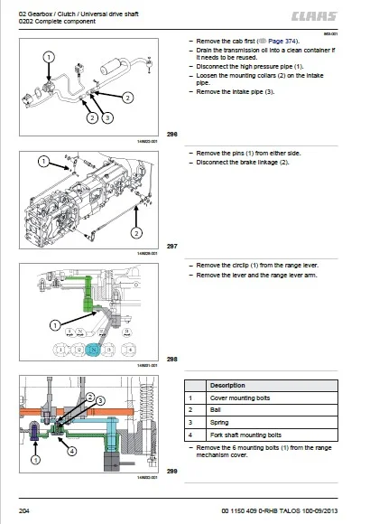
02 Gearbox / Clutch / Universal drive shaft197
0202 Complete component197
Transmission general view197
Removing/refitting the transmission197
Transmission inspection199
Faults and solutions199
Separating the clutch housing from the central housing200
Separating the central housing from the rear axle housing203
0215 Mechanical clutch206
Clutch inspection and repair206
Special tools206
Clutch operation206
Specifications207
Clutch cross-sectional view207
Clutch disc / Sleeve assembly208
Inspection and solutions209
Separating the clutch and sleeve210
Clutch disc inspection210
Inspecting the pressure plate210
Refitting the clutch and sleeve211
Removing the clutch release fork and bearing211
Refitting the clutch release bearing212
0218 Clutch control213
0220 Mechanical reverser214
Direction reversal system214
Clutch housing (direction reverser) – Cross-sectional view214
Clutch housing components (direction reverser)215
Direction reverser operation215
Removing the direction reverser system215
0228 Reverser control217
Direction reversal system217
Forward/reverse gear fork shaft217
0230 Mechanical gearbox218
Main transmission system218
Gearbox218
Removing the gearbox218
Range box222
Cross-sectional view222
Removing the range box (components)223
0238 Gearbox control226
Gearbox226
Gear lever operation226
Inspecting the synchros226
Gearbox synchro drive train226
1st gear drive226
2nd gear drive227
3rd gear drive227
4th gear drive227
Range box228
Range lever operation228
Drive train228
1st range drive228
2nd range drive228
3rd range drive229
4th range drive229
0240 Rear axle housing230
Repairing the rear axle housing230
Rear axle housing – Cross-sectional view230
Removing the brakes231
Axle tube – Cross-sectional view233
Removing the final drives234
Reassembling the rear axle235
0242 Differential236
Rear differential locking system236
Special tools236
Rear differential lock – Cross-sectional view237
Rear differential lock238
Removing the differential lock fork238
Differential drive pinion shaft – Cross-sectional view240
Removing the drive pinion shaft241
Refitting the drive pinion shaft242
Setting the clearance between the teeth and the drag torque243
0252 Electro-hydraulical front axle drive245
4-wheel drive transmission245
4-wheel drive transmission – Cross-sectional views245
4-wheel drive transmission operation247
Removing the 4-wheel drive transmission247
03 Chassis251
0325 Driven steering axle, front251
Front axle – General view251
Repairing the front axle252
Wheel hub – Exploded view256
Repairing the wheel hub and pivot257
Removing / Refitting the front axle262
Removing the steering cylinder262
Removing the steering rod263
Removing the wheel reduction gear263
Removing the wheel shafts263
Removing the front axle differential264
Refitting the front axle differential264
Adjusting the drive pinion and front axle differential265
Drive pinion and front axle differential – Cross-sectional view265
Setting the position of the drive pinion shaft266
Preloading the drive pinion bearing266
Clearance between the teeth on the drive pinion and the crown wheel266
Calibrating the drive pinion267
04 Brake269
0405 Service brake269
Brake system269
Brake system – Cross-sectional view269
Operation270
Removing the brakes and rear differential270
0415 Parking brake273
Handbrake273
Handbrake operation273
05 Steering274
0505 Steering274
Steering274
Hydrostatic steering system274
Faults and solutions274
Removing the steering gearbox275
Refitting the steering gearbox275
06 Lift device277
0605 Rear power lift277
Rear hydraulic lifting system277
Linkage cover – Cross-sectional view277
Description278
Neutral position –> Arm raised278
Arm raised –> Neutral position278
Neutral position –> Arm lowered279
Arm lowered –> Neutral position279
Hydraulic linkage control valve block280
Cross-sectional view280
Arm neutral phase281
Arm lifting phase283
Arm lowering phase284
Tightening torques286
Lowering speed adjustment valve and cylinder safety valve287
Removing the linkage cover288
Removing the linkage291
Adjusting the lifting rods294
Faults and solutions294
08 Drives297
0802 Rear PTO297
Power take-off297
Power take-off (3 speeds) – Cross-sectional view297
Power take-off control298
Removing the power take-off299
09 Hydraulic system301
0915 Hydraulic lines301
Description of the hydraulic system301
Special tools302
Hydraulic circuit components304
306
Hydraulic system diagram310
Low pressure circuit311
Independent power take-off control312
Independent power take-off clutch – Cross-sectional view313
Power take-off disengagement (lubrication)314
Engagement of the power take-off314
0920 Valves315
Auxiliary hydraulic control valves315
Auxiliary hydraulic control valve control315
Connections316
Operation317
Hydraulic circuit diagram317
Fitting/removal318
Front electrohydraulic block319
Front pressure outlet320
Front electrohydraulic block321
Auxiliary spool valve321
10 Electrical / Electronic equipment322
1000 General electrical system322
Electrical system – General points322
Technical specifications322
Special tools323
Fault finding324
Key for function diagrams and installation diagrams326
Changing the bulbs327
Front lights327
Indicators and side lights329
Rear lights330
Front/rear work lights331
Cab interior lighting332
1005 Power supply333
Engine333
Starting safety switch333
S064 Key-operated ignition333
Y015 Engine stop solenoid valve334
Engine stop relay335
Starting relay335
Preheating timer336
Preheating relay336
Fuse wire337
Cab337
R032 Cigarette lighter337
S015 Daytime running lights switch338
Cab supply relay339
Flashing unit339
Power take-off340
S114 Rear power take-off “on/off” switch340
Power take-off pressure warning relay340
Lifting341
Automatic lift relay (optional)341
1012 Modules / sensors343
Terminal module A101343
Tachometer344
Running time counter344
Fuel gauge345
Coolant temperature345
Engine sensors345
B045 Coolant temperature sensor345
B381 Fuel filter water sensor346
R035 Fuel level resistor346
Z042 Engine oil pressure switch346
Transmission sensors347
B123 Transmission fluid temperature sensor347
B229 Gearbox speed intermediate sensor347
B361 Clutch pedal sensor347
Range sensor348
Brake sensors348
Z126 Left-hand brake pedal switchZ127 Right-hand brake pedal switch348
Pedals uncoupled switch349
Steering sensor350
B117 Wheel angle sensor350
Lifting351
B144 Force sensor351
B334 Rear linkage position sensorB407 Working depth sensor352
1015 Wiring harnesses353
Harness identification354
Harness 1: Engine harness356
Engine, front section357
Harness 2: Bonnet358
Front lighting358
Harnesses 3 and 4: Front section and dashboard harnesses358
Cab version360
362
Platform version364
366
Harness 5367
Under cab367
Under platform368
Harness 6 – Cab368
Air conditioning373
12 Cab / Operator’s platform374
1210 Cab374
Removing the cab374
Removing the fuel tanks377
Draining the tanks377
Removal377
Right-hand side of engine379
Left-hand side of engine380
Left-hand section381
Right-hand section383
Right-hand console386
Removal386
Refitting388
Rear wiper motor388
Removal388
Refitting389
Front wiper motor389
Removal389
Refitting391
Loudspeaker391
Removal391
Refitting392
Audio equipment392
Removal392
Refitting393
Door393
Removal393
Refitting394
1240 Air condition395
Description of the air conditioning/heating system395
Components395
Heating/air conditioning circuit397
Specifications – air conditioning398
Maintenance of the air conditioning system399
Periodic maintenance operations399
Every 6 months399
Every year399
Every 2 years400
Checks and adjustments400
Refrigerant400
Radiator and condenser harnesses401
V-belt tension402
Duct connections402
Air conditioning and heating – Faults and solutions402
Fault finding406
Heating/air conditioning controls407
Removal407
Refitting408
Air conditioning unit408
Preliminary operations408
Opening the cab roof408
Removing the air conditioning unit409
Refitting412
Disassembling the air conditioning unit412
Reassembling the air conditioning unit414
Condenser415
Removal415
Refitting417
Compressor417
Removal417
Refitting419
Position of components420
Electric system420
Location of components420
Location of components on the engine423
Z042 Engine oil pressure switch423
B045 Coolant temperature sensor424
B381 Fuel filter water sensor424
Y015 Engine stop solenoid valve424
Location of components on the transmission425
B144 Force sensor427
B334 Rear linkage position sensorB407 Working depth sensor427
Range sensor427
B123 Transmission fluid temperature sensor428
B229 Gearbox speed intermediate sensor428
Location of instrument panel components429
Starting relay430
Power take-off pressure warning relay430
Preheating timer431
Flashing unit431
Engine stop relay431
B361 Clutch pedal sensor432
Starting safety switch432
Cab supply relay432
Automatic lift relay (optional)433
Z126 Left-hand brake pedal switchZ127 Right-hand brake pedal switch433
Pedals uncoupled switch433
Location of cab components434
S015 Daytime running lights switch434
S114 Rear power take-off “on/off” switch434
S064 Key-operated ignition435
R032 Cigarette lighter (cab version)435
Location of components – Miscellaneous435
B117 Wheel angle sensor435
R035 Fuel level resistor436
Preheating relay436
Fuse wire436
Index437
4437
A437
B437
C438
D440
E440
F441
G442
H443
I443
J444
K444
L444
M444
O444
P445
R445
S447
T448
U448
V448
W449
IMAGES PREVIEW OF THE MANUAL:
CLAAS TALOS 130-120 REPAIR MANUAL – PDF DOWNLOAD:
PLEASE NOTE:
- This is the same manual used by the DEALERSHIPS to SERVICE your vehicle.
- The manual can be all yours – Once payment is complete, you will be taken to the download page from where you can download the manual. All in 2-5 minutes time!!
- Need any other service / repair / parts manual, please feel free to contact us at heydownloadss @gmail.com . We may surprise you with a nice offer