CLAAS TARGO K50 K60 K70 HYDRAULICS ELECTRICS TECHNICAL DATA Repair manual
Original price was: $67.00.$24.95Current price is: $24.95.
CLAAS TARGO K50 K60 K70 HYDRAULICS ELECTRICS TECHNICAL DATA Repair manual
Description
CLAAS TARGO K50 K60 K70 HYDRAULICS ELECTRICS TECHNICAL DATA Repair manual
DESCRIPTION:
CLAAS TARGO K50 K60 K70 HYDRAULICS ELECTRICS TECHNICAL DATA Repair manual
INTRODUCTION
General
The contents of this Repair Manual, although correct at the time of publication, may be subject to alteration by the manufacturer without notice. This manual assumes that maintenance personnel have a sound knowledge of workshop practices and safety procedures associated with the repairs of this type of machine. This manual is designed to assist with the more specialised information required for removal and strip-down of major components. It is recommended that the relevant part of this Repair Manual is studied carefully before proceeding with any maintenance.
TABLE OF CONTENTS:
CLAAS TARGO K50 K60 K70 HYDRAULICS ELECTRICS TECHNICAL DATA Repair manual
INTRODUCTION
General
Machine identification
Health and Safety
SAFETY WARNINGS
SECTION 1
HYDRAULICS
CONTENTSj
Description and Operation 1.1
Description 1.1
General 1.1
Dumping (dissipation) of hydraulic pressure 1.1
To dump brake system pressure 1.1
To dump a system pressure 1.1
Hydraulic Circuit – Single Circuit Braking (up to Machines S/No.51200317) 1.2
Hydraulic Circuit – Single Circuit Braking (from Machines S/No.51200318 to 51200471) 1.4
Hydraulic Circuit – Single Circuit Braking (from Machines S/No.51200472 to 51200551) 1.6
Hydraulic Circuit – Single Circuit Braking (from Machines S/No.51200552 to 51200727) 1.8
Hydraulic Circuit – Dual Circuit Braking (up to Machines S/No.51200317) 1.10
Hydraulic Circuit – Dual Circuit Braking (from Machines S/No.51200318 to 51200471) 1.12
Hydraulic Circuit – Dual Circuit Braking (from Machines S/No.51200472 to 51200551) 1.14
Hydraulic Circuit – Dual Circuit Braking (from Machines S/No.51200552 to 51200727) 1.16
Components
General 1.18
Hydraulic tank 1.18
Suction line connections to hydraulic tank 1.18
Return hose connections to hydraulic tank (up to Machines S/No.51200471) 1.18
Return hose connections to hydraulic tank (from Machines S/No.51200472) 1.18
Hydraulic pump (load sensing) 1.19
Pump compensator (load sensing) 1.19
Tank filter 1.19
Filler/Breather 1.19
Auxiliary hydraulic pump 1.19
Fan motor (up to Machines S/No.51200471) 1.20
Fan reverse motor (from Machines S/No.51200472) 1.20
Pressure reducing valve (PRV) for the parking brake (up to Machines S/No.51200551) 1.21
Pressure filter 1.21
Single circuit brake pressure servo valve (MICO) (up to Machines S/No.51200471) 1.22
Duel circuit brake pressure servo valve (MICO) (up to Machines S/No.51200471) 1.22
Single circuit brake pressure servo valve (SAFIM} (from Machines S/No.51200472) 1.23
Duel circuit brake pressure servo valve (SAFIN) (from Machines S/No.51200472) 1.23
Accumulator(s) 1.24
Pressure switch 1.24
Pressure switch (transmission dump) 1.24
Front axle 1.25
Steering cylinder (front) 1.25
Pressure switch (brake light) 1.25
Pressure switch (parking brake) 1.26
Rear axle 1.26
Steering cylinder (rear) 1.26
Non-return valve 1.26
Steering valve 1.27
Steering in Neutral position 1.27
Steering in Operation 1.28
Pressure relief valve 1.28
Steering selector valve 1.29
lcoNTENTS
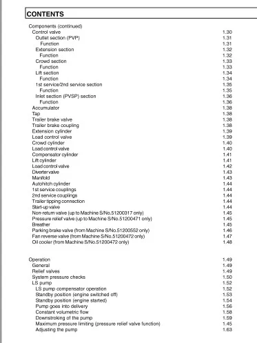
Components (continued)
Control valve
Outlet section (PVP)
Function
Extension section
Function
Crowd section
Function
Lift section
Function
1st service/2nd service section
Function
Inlet section (PVSP) section
Function
Accumulator
Tap
Trailer brake valve
Trailer brake coupling
Extension cylinder
Load control valve
Crowd cylinder
Load control valve
Compensator cylinder
Lift cylinder
Load control valve
Divertervalve
Manifold
Autohitch cylinder
1st service couplings
2nd service couplings
Trailer tipping connection
Start-up valve
Non-return valve (up to Machine S/No.51200317 only)
Pressure relief valve (upto Machine S/No.51200471 only)
Breather
Parking brake valve (from Machine S/No.51200552 only)
Fan reverse valve (from Machine S/No.51200472 only)
Oil cooler (from Machine S/No.51200472 only)
Operation
General
Relief valves
System pressure checks
LS pump
LS pump compensator operation
Standby position (engine switched off)
Standby position (engine started)
Pump goes into delivery
Constant volumetric flow
Downstroking of the pump
Maximum pressure limiting (pressure relief valve function)
Adjusting the pump
g55笾笾笱笱邸邸郘郘邹邹部部郤郤弱弱AOAO 引引应总总”“”“”ASASAS 舫叮犯
1111111111111111111111111111111111111
14194194195105125125135145165185194156 3
lcoNTENTS
Maintenance
Torque tightening
Hydraulic level
Check
Hydraulic tank
Removal
Installation
Hydraulic pump (LS)
Removal
Installation
Auxiliary hydraulic pump
Removal
Installation
Fan motor (up to Machines S/No.51200471 only)
Removal
Installation
Fan motor bearings (up to Machines S/No.51200471 only)
Removal
Installation
Fan motor (from Machines S/No.51200472 only)
Removal
Installation
Fan drive bearings (from Machines S/No.51200472 only)
Removal
Installation
Fan reverse valve (from Machines S/No.51200472 only)
Removal
Installation
Parking brake valve (from Machines S/No.51200472 only)
Removal
Installation
Hydraulic filter
Removal
Installation
Brake valve (MICO) (up to Machines S/No.51200471 only)
Operation
Brake valve (SAFIM) (from Machines S/No.51200472 only)
Operation
Single brake valve (MICO) (up to Machines S/No.51200471 only)
Removal
Installation
Servicing
Dismantling
Assembly
Single brake valve (SAFIM) (from Machines S/No.51200472 only)
Removal
Installation
Servicing
Dismantling (General)
Assembly (General)
Dismantling (Brake master module)
Assembly (Brake master module)
Dismantling (Brake valve module)
Assembly (Brake valve module)
1614614616616617617617618618618619619619710710710711711711712712712713713713714714714715715715716716716717717717717718718718719
lcoNTENTS
Dual brake valve (MICO) (up to Machines S/No.51200471 only)
Removal
Installation
Servicing
Dismantling
Assembly
Dual brake valve (SAFIM) (from Machines S/No.51200472 only)
Removal
Installation
Servicing
Removal and installation (General)
Dismantling (Brake master module)
Assembly (Brake master module)
Dismantling (Brake valve module)
Assembly (Brake valve module)
Trailer brake valve
Removal
Installation
Servicing
Dismantling
Assembly
Brake system bleeding
General
Diverter valve
Removal
Installation
Manifold
Removal
Installation
Control valve
Removal
Installation
Servicing
Dismantling
Assembly
Spool sections
General
Dismantling
Assembly
Inlet section (PVSP)
General
Dismantling
Assembly
Outlet section (PVP)
General
Dismantling
Assembly
Steering
Description
Operation
Checking the steering system
Steering cylinder
Steering unit (OSPF)
Servicing
Steering valve assembly
Removal
I nstal lat ion
Servicing
Dismantling
Assembly
1.85
1.85
1.85
1.86
1.86
1.88
1.89
1.89
1.89
1.90
1.90
1.90
1.90
1.91
1.91
1.92
1.92
1.92
1.93
1.93
1.94
1.95
1.95
1.96
1.96
1.96
1.97
1.97
1.97
1.98
1.98
1.98
1.99
1.99
1.99
1.101
1.101
1.101
1.101
1.103
1.103
1.103
1.103
1.104
1.104
1.104
1.104
1.105
1.105
1.105
1.107
1.107
1.107
1.107
1.108
1.108
1.108
1.109
1.109
1.109
CONTENTSJ
Hydraulic cylinders
Extension cylinder
Removal
Installation
Crowd cylinder
Removal
Installation
Compensator cylinder
Removal
Installation
Lift cylinder
Removal
Installation
Extension, crowd, compensator and lift cylinder
Servicing
Dismantling
Assembly
Autohitch cylinder
Removal
Installation
Dismantling
Assembly
Carriage locking cylinder
Removal
Installation
Dismantling
Assembly
Steering cylinder
Removal
Installation
Dismantling
Assembly
11101101101111121121121131131131141141141151151151151171171171171181191191191192102112112112122 ……
…………………….
11111111111111111111111111111111
SECTION 2
ELECTRICS
Circuit diagrams
Circuit diagram key – Wiring terminations 2.1
Circuit diagram key- Components 2.2
Circuit diagram key- General Information 2.4
Power generation, Starting, Non APC (Sheet 1) 2.4
Power generation, Starting, With APC (Sheet 1 A) 2.5
Hydraulic controls, Steering control, Safe load indicator, Large lock out relay (Sheet 2) 2.6
Hydraulic controls, Steering control, Safe load indicator, Mini lock out relay (Sheet 2A} 2.7
Wipers, Washers, Horn, Worklights (Sheet 3) 2.8
Wipers, Washers, Horn, Worklights combined boom/side worklights, Switching (Sheet 3A} 2.9
Head/side lights, Fog lights, Number plate lights, Head Flasher (Sheet 4) 2.1 O
Head/side lights, Fog lights, Number plate lights, Head Flasher (Sheet 4A) 2.11
Turn indicators, Reverse lamps, Steer sensors, Stop lights, Radio (Sheet 5) 2.12
Inst display, Sensor switches, Fan motor, Aircon, Interior light, Beacon, Fuel Sender,
Fan reverse, Hydraulic temp. (Sheet 6) 2.13
APC 50 with lgn controlled APC bat feed, Screened sensor cable, P/brake link (Sheet 7) 2.14
Non APC,Correct P/brake and trans dump, No P/brake controller, Circuit link (Sheet 7 A) 2.15
Chassis loom (Illustration) 2.16
Engine loom (Illustration) 2.17
Cab loom (Illustration) 2.18
lcoNTENTS
Longitudinal stability indicator
Description
Sensor
Specification
Display Module
Specification
Testing and adjustment
Troubleshooting
Visual inspection
System check
Error indications from the display module
Sensor – test
General
Procedure to test the operation of the sensor
Procedure to install a sensor
Procedure to replace the display module
Calibration
Calibration procedure
Resetting the zero point
Testing load sensor function
Functional test of load sensor indicator
Procedure
Main instrument panel
Description
Removal
Installation
Functional description
Solo control joystick
Removal
Installation
Starter
Removal
Installation
Fusebox and relays
Description
Removal
Installation
Alternator
Alternator drive belt check
Removal
Installation
Automatic powershift
Automatic powershift controller
Removal
Installation
Forward/ Neutral/ Reverse (FNR) switch assembly
Removal
Installation
2.19
2.19
2.20
2.20
2.20
2.20
2.23
2.23
2.23
2.24
2.25
2.25
2.25
2.26
2.27
2.28
2.29
2.29
2.31
2.32
2.32
2.33
2.34
2.34
2.34
2.34
2.35
2.36
2.36
2.36
2.37
2.37
2.37
2.38
2.38
2.38
2.38
2.40
2.40
2.41
2.41
2.42
2.42
2.42
2.42
2.43
2.43
2.43
CONTENTS I
SECTION 3
TECHNICAL DATA
Dimensions
Performance
Machine speed (km/hr) for 106 hp
Carriage
Cycle time
Engine
Cooling
Transmission
Tyres
Hydraulics
Electrics
Capacities
313232333334343434353535
IMAGES PREVIEW OF THE MANUAL:
Need help? Contact: [email protected]
PLEASE NOTE:
- This is the SAME manual used by the dealers to troubleshoot any faults in your vehicle. This can be yours in 2 minutes after the payment is made.
- Contact us at [email protected] should you have any queries before your purchase or that you need any other service / repair / parts operators manual.
S.M