CLAAS TARGO K50 K60 K70 HYDRAULICS &ELECTRICS TECHNICAL REPAIR MANUAL – PDF DOWNLOAD
Original price was: $78.00.$22.95Current price is: $22.95.
CLAAS TARGO K50 K60 K70 HYDRAULICS &ELECTRICS TECHNICAL REPAIR MANUAL – PDF DOWNLOAD
Description
CLAAS TARGO K50 K60 K70 HYDRAULICS &ELECTRICS TECHNICAL REPAIR MANUAL – PDF DOWNLOAD
DESCRIPTION:
CLAAS TARGO K50 K60 K70 HYDRAULICS &ELECTRICS TECHNICAL REPAIR MANUAL – PDF DOWNLOAD
INTRODUCTION
General
- The contents of this Repair Manual, although correct at the time of publication, may be subject to alteration by the manufacturer without notice.
- This manual assumes that maintenance personnel have a sound knowledge of workshop practices and safety procedures associated with the repairs of this type of machine.
- This manual is designed to assist with the more specialised information required for removal and strip-down of major components. It is recommended that the relevant part of this Repair Manual is studied carefully before proceeding with any maintenance.
TABLE OF CONTENTS:
CLAAS TARGO K50 K60 K70 HYDRAULICS &ELECTRICS TECHNICAL REPAIR MANUAL – PDF DOWNLOAD
INTRODUCTION
General
Machine identification
Health and Safety
SAFETY WARNINGS
SECTION 1
HYDRAULICS
Description and Operation 1.1
Description 1.1
General 1.1
Dumping (dissipation) of hydraulic pressure 1.1
To dump brake system pressure 1.1
To dump a system pressure 1.1
Hydraulic Circuit – Single Circuit Braking (up to Machines S/No.51200317) 1.2
Hydraulic Circuit – Single Circuit Braking (from Machines S/No.51200318 to 51200471) 1.4
Hydraulic Circuit – Single Circuit Braking (from Machines S/No.51200472 to 51200551) 1.6
Hydraulic Circuit – Single Circuit Braking (from Machines S/No.51200552 to 51200727
& K5D00100, K6D00100, K7D00100 onwards) 1.8
Hydraulic Circuit – Dual Circuit Braking (up to Machines S/No.51200317) 1.10
Hydraulic Circuit – Dual Circuit Braking (from Machines S/No.51200318 to 51200471) 1.12
Hydraulic Circuit – Dual Circuit Braking (from Machines S/No.51200472 to 51200551) 1.14
Hydraulic Circuit – Dual Circuit Braking (from Machines S/No.51200552 to 51200727
& K5D00100, K6D00100, K7D00100 onwards) 1.16
Components
General 1.18
Hydraulic tank 1.18
Suction line connections to hydraulic tank 1.18
Return hose connections to hydraulic tank (up to Machines S/No.51200471) 1.18
Return hose connections to hydraulic tank (from Machines S/No.51200472) 1.18
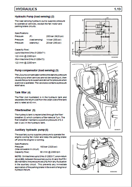
Hydraulic pump (load sensing) 1.19
Pump compensator (load sensing) 1.19
Tank filter 1.19
Filler/Breather 1.19
Auxiliary hydraulic pump 1.19
Fan motor (up to Machines S/No.51200471) 1.20
Fan reverse motor (from Machines S/No.51200472) 1.20
Pressure reducing valve (PRV) for the parking brake (up to Machines S/No.51200551) 1.21
Pressure filter 1.21
Single circuit brake pressure servo valve (MICO) (up to Machines S/No.51200471) 1.22
Dual circuit brake pressure servo valve (MICO) (up to Machines S/No.51200471) 1.22
Single circuit brake pressure servo valve (SAFIM) (from Machines S/No.51200472
& K5D00100, K6D00100, K7D00100 onwards) 1.23
Dual circuit brake pressure servo valve (SAFIN) (from Machines S/No.51200472
& K5D00100, K6D00100, K7D00100 onwards) 1.23
Accumulator(s) 1.24
Pressure switch 1.24
Pressure switch (transmission dump) 1.24
Front axle 1.25
Steering cylinder (front) 1.25
Pressure switch (brake light) 1.25
Pressure switch (parking brake) 1.26
Rear axle 1.26
Steering cylinder (rear) 1.26
Non-return valve 1.26
Steering valve 1.27
Steering in Neutral position 1.27
Steering in Operation 1.28
Pressure relief valve 1.28
Steering selector valve 1.29
CONTENTS
CONTENTS
Components (continued)
Control valve 1.30
Outlet section (PVP) 1.31
Function 1.31
Extension section 1.32
Function 1.32
Crowd section 1.33
Function 1.33
Lift section 1.34
Function 1.34
1st service/2nd service section 1.35
Function 1.35
Inlet section (PVSP) section 1.36
Function 1.36
Accumulator 1.38
Tap 1.38
Trailer brake valve 1.38
Trailer brake coupling 1.38
Extension cylinder 1.39
Load control valve 1.39
Crowd cylinder 1.40
Load control valve 1.40
Compensator cylinder 1.41
Lift cylinder 1.41
Load control valve 1.42
Diverter valve 1.43
Manifold 1.43
Autohitch cylinder 1.44
1st service couplings 1.44
2nd service couplings 1.44
Trailer tipping connection 1.44
Start-up valve 1.44
Non-return valve (up to Machine S/No.51200317 only) 1.45
Pressure relief valve (up to Machine S/No.51200471 only) 1.45
Breather 1.45
Parking brake valve (from Machine S/No.51200552 to 51200727
& K5D00100, K6D00100, K7D00100 onwards) 1.46
Fan reverse valve (from Machine S/No.51200472 to 51200727
& K5D00100, K6D00100, K7D00100 onwards) 1.47
Oil cooler (from Machine S/No.51200472 to 51200727
& K5D00100, K6D00100, K7D00100 onwards) 1.48
Operation 1.49
General 1.49
Relief valves 1.49
System pressure checks 1.50
LS pump 1.52
LS pump compensator operation 1.52
Standby position (engine switched off) 1.53
Standby position (engine started) 1.54
Pump goes into delivery 1.56
Constant volumetric flow 1.58
Downstroking of the pump 1.59
Maximum pressure limiting (pressure relief valve function) 1.45
Adjusting the pump 1.63
Maintenance 1.64
Torque tightening 1.64
Hydraulic level 1.66
Check 1.66
Hydraulic tank 1.67
Removal 1.67
Installation 1.67
Hydraulic pump (LS) 1.68
Removal 1.68
Installation 1.68
Auxiliary hydraulic pump 1.69
Removal 1.69
Installation 1.69
Fan motor (up to Machines S/No.51200471 only) 1.70
Removal 1.70
Installation 1.70
Fan motor bearings (up to Machines S/No.51200471 only) 1.71
Removal 1.71
Installation 1.71
Fan motor (from Machines S/No.51200472 to 51200727
& K5D00100, K6D00100, K7D00100 onwards) 1.72
Removal 1.72
Installation 1.72
Fan drive bearings (from Machines S/No.51200472 to 51200727
& K5D00100, K6D00100, K7D00100 onwards) 1.73
Removal 1.73
Installation 1.73
Fan reverse valve (from Machines S/No.51200472 to 51200727
& K5D00100, K6D00100, K7D00100 onwards) 1.74
Removal 1.74
Installation 1.74
Parking brake valve (from Machines S/No.51200472 to 51200727
& K5D00100, K6D00100, K7D00100 onwards) 1.75
Removal 1.75
Installation 1.75
Hydraulic filter 1.76
Removal 1.76
Installation 1.76
Brake valve (MICO) (up to Machines S/No.51200471 only) 1.77
Operation 1.77
Brake valve (SAFIM) (from Machines S/No.51200472 to 51200727
& K5D00100, K6D00100, K7D00100 onwards) 1.77
Operation 1.77
Single brake valve (MICO) (up to Machines S/No.51200471 only) 1.78
Removal 1.78
Installation 1.78
Servicing 1.79
Dismantling 1.79
Assembly 1.80
Single brake valve (SAFIM) (from Machines S/No.51200472 to 51200727
& K5D00100, K6D00100, K7D00100 onwards) 1.81
Removal 1.81
Installation 1.81
Servicing 1.82
Dismantling (General) 1.82
Assembly (General) 1.82
Dismantling (Brake master module) 1.83
Assembly (Brake master module) 1.83
Dismantling (Brake valve module) 1.84
Assembly (Brake valve module) 1.84
CONTENTS
Dual brake valve (MICO) (up to Machines S/No.51200471 only) 1.85
Removal 1.85
Installation 1.85
Servicing 1.86
Dismantling 1.86
Assembly 1.88
Dual brake valve (SAFIM) (from Machines S/No.51200472 to 51200727
& K5D00100, K6D00100, K7D00100 onwards) 1.89
Removal 1.89
Installation 1.89
Servicing 1.90
Removal and installation (General) 1.90
Dismantling (Brake master module) 1.90
Assembly (Brake master module) 1.90
Dismantling (Brake valve module) 1.91
Assembly (Brake valve module) 1.91
Trailer brake valve 1.92
Removal 1.92
Installation 1.92
Servicing 1.93
Dismantling 1.93
Assembly 1.94
Brake system bleeding 1.95
General 1.95
Diverter valve 1.96
Removal 1.96
Installation 1.96
Manifold 1.97
Removal 1.97
Installation 1.97
Control valve 1.98
Removal 1.98
Installation 1.98
Servicing 1.99
Dismantling 1.99
Assembly 1.99
Spool sections 1.101
General 1.101
Dismantling 1.101
Assembly 1.101
Inlet section (PVSP) 1.103
General 1.103
Dismantling 1.103
Assembly 1.103
Outlet section (PVP) 1.104
General 1.104
Dismantling 1.104
Assembly 1.104
Steering 1.105
Description 1.105
Operation 1.105
Checking the steering system 1.107
Steering cylinder 1.107
Steering unit (OSPF) 1.107
Servicing 1.107
Steering valve assembly 1.108
Removal 1.108
Installation 1.108
Servicing 1.109
Dismantling 1.109
Assembly 1.109
CONTENTS
Hydraulic cylinders 1.110
Extension cylinder 1.110
Removal 1.110
Installation 1.111
Crowd cylinder 1.112
Removal 1.112
Installation 1.112
Compensator cylinder 1.113
Removal 1.113
Installation 1.113
Lift cylinder 1.114
Removal 1.114
Installation 1.114
Extension, crowd, compensator and lift cylinder 1.115
Servicing 1.115
Dismantling 1.115
Assembly 1.115
Autohitch cylinder 1.117
Removal 1.117
Installation 1.117
Dismantling 1.117
Assembly 1.118
Carriage locking cylinder 1.119
Removal 1.119
Installation 1.119
Dismantling 1.119
Assembly 1.120
Steering cylinder 1.121
Removal 1.121
Installation 1.121
Dismantling 1.122
Assembly 1.122
SECTION 2
ELECTRICS
Circuit diagrams Tier 0 & 1 (Refer to the Serial Number Table in Contents)
Circuit diagram key – Wiring terminations 2.1
Circuit diagram key – Components 2.2
Circuit diagram key – General Information 2.3
Power generation, Starting, Non APC (Sheet 1) 2.4
Power generation, Starting, With APC (Sheet 1A) 2.5
Hydraulic controls, Steering control, Safe load indicator, Large lock out relay (Sheet 2) 2.6
Hydraulic controls, Steering control, Safe load indicator, Mini lock out relay (Sheet 2A) 2.7
Wipers, Washers, Horn, Worklights (Sheet 3) 2.8
Wipers, Washers, Horn, Worklights combined boom/side worklights, Switching (Sheet 3A) 2.9
Head/side lights, Fog lights, Number plate lights, Head Flasher (Sheet 4) 2.10
Head/side lights, Fog lights, Number plate lights, Head Flasher (Sheet 4A) 2.11
Turn indicators, Reverse lamps, Steer sensors, Stop lights, Radio (Sheet 5) 2.12
Inst display, Sensor switches, Fan motor, Aircon, Interior light, Beacon, Fuel Sender,
Fan reverse, Hydraulic temp. (Sheet 6) 2.13
APC 50 with Ign controlled APC bat feed, Screened sensor cable, P/brake link (Sheet 7) 2.14
Non APC,Correct P/brake and trans dump, No P/brake controller, Circuit link (Sheet 7A) 2.15
Circuit diagrams Tier 2 (Refer to the Serial Number Table in Contents)
Circuit diagram key – Wiring terminations 2.16
Circuit diagram key – Components 2.17
Circuit diagram key – General Information 2.18
Power generation, Starting, With APC, Boom/side worklights power harness (Sheet 1) 2.19
Hydraulic controls, Steering control, Safe load indicator, Large lock out relay (Sheet 2) 2.20
Wipers, Washers, Horn, Worklights (Sheet 3) 2.21
Wipers, Washers, Horn,Worklights combined boom/side worklights,Switching (Sheet 4) 2.22
CONTENTS
Wipers, Washers, Horn, Worklights combined boom/side worklights switching, Boom/side
worklights Power Harness (Sheet 5) 2.23
Head/side lights, Fog lights, Number plate lights, Head Flasher (Sheet 6) 2.24
Head/side lights, Fog lights, Number plate lights, Head Flasher (Sheet 7) 2.25
Turn indicators, Reverse lamps, Steer sensors, Stop lights, Radio (Sheet 8) 2.26
Inst display, Sensor switches, Fan motor, Aircon, Interior light, Beacon, Fuel Sender,
Fan reverse, Hydraulic temp. (Sheet 9) 2.27
APC 50 with Ign controlled APC bat feed, Screened sensor cable,P/brake link (Sheet 10) 2.28
ELECTRICS continued Tier 0 & 1 (Refer to the Serial Number Table in Contents)
Chassis loom (Illustration) 2.29
Engine loom (Illustration) 2.30
Cab loom (Illustration) 2.31
Longitudinal stability indicator 2.32
Description 2.32
Sensor 2.33
Specification 2.33
Display Module 2.33
Specification 2.33
Testing and adjustment 2.36
Troubleshooting 2.36
Visual inspection 2.36
System check 2.37
Error indications from the display module 2.38
Sensor – test 2.38
General 2.38
Procedure to test the operation of the sensor 2.39
Procedure to install a sensor 2.40
Procedure to replace the display module 2.41
Calibration 2.42
Calibration procedure 2.42
Resetting the zero point 2.44
Testing load sensor function 2.45
Functional test of load sensor indicator 2.45
Procedure 2.46
Main instrument panel 2.47
Description 2.47
Removal 2.47
Installation 2.47
Functional description 2.48
Solo control joystick 2.49
Removal 2.49
Installation 2.49
Starter 2.50
Removal 2.50
Installation 2.50
Fusebox and relays 2.51
Description 2.51
Removal 2.51
Installation 2.51
Alternator 2.53
Alternator drive belt check 2.53
Removal 2.54
Installation 2.54
Automatic powershift 2.55
Automatic powershift controller 2.55
Removal 2.55
Installation 2.55
Forward / Neutral / Reverse (FNR) switch assembly 2.56
Removal 2.56
Installation 2.56
CONTENTS
CONTENTS
SECTION 3
TECHNICAL DATA
Dimensions 3.1
Performance 3.2
Machine speed (km/hr) for 106 hp 3.2
Carriage 3.3
Cycle time 3.3
Engine 3.4
Cooling 3.4
Transmission 3.4
Tyres 3.4
Hydraulics 3.5
Electrics 3.5
Capacities 3.5
IMAGES PREVIEW OF THE MANUAL:
CLAAS TARGO K50 K60 K70 HYDRAULICS &ELECTRICS TECHNICAL REPAIR MANUAL – PDF DOWNLOAD:
PLEASE NOTE:
- This is the SAME MANUAL used by the dealerships to diagnose your vehicle
- No waiting for couriers / posts as this is a PDF manual and you can download it within 2 minutes time once you make the payment.
Your payment is all safe and the delivery of the manual is INSTANT – You will be taken to the DOWNLOAD PAGE. - So have no hesitations whatsoever and write to us about any queries you may have : heydownloadss @gmail.com
S.M